Embed Size (px)
Citation preview
1 AC 21-38(0): Aircraft Electrical Load Analysis and Power Source Capacity
31 March 2005
AC 21-38(0) MARCH 2005
AIRCRAFT ELECTRICAL LOAD ANALYSIS AND POWER SOURCE CAPACITY
CONTENTS 1. References 1
2. Purpose 1
3. Status of this Advisory Circular 1
4. Introduction 2
5. Definitions 2
6. General Requirements 4
7. Electrical Load Analyses — Basic Principles 4
Appendix 1 Typical DC Electrical Load Analysis (Normal And Emergency) 15
Appendix 2 Electrical Load Analysis (AC – Current) – Normal Operating Conditions 17
Appendix 3 Electrical Systems 19
1. REFERENCES Civil Aviation Safety Regulations
(CASR) 21.017 – Designation of Applicable Airworthiness Standards, 21.091 – Changes to Type Certificates, 21.115 – Supplemental Type Certificates.
CASA Advisory Circular 21-99 - Aircraft Wiring and Bonding.
RTCA DO-160D: Environmental Conditions and Test Procedures for Airborne Equipment Section 16 (Power Input).
Military Specification MIL-E-7016F: Electrical Load and Power Source Capacity, Aircraft, Analysis of.
Federal Aviation Administration (FAA) Advisory Circular 43.13-1B: Acceptable Methods, Techniques and Practices – Aircraft Inspection and Repair.
2. PURPOSE The purpose of this Advisory Circular is to provide guidance material for the preparation of an Electrical Load Analysis (ELA).
3. STATUS OF THIS ADVISORY CIRCULAR This is the first issue of this Advisory Circular to be written on aircraft electrical systems.
Advisory Circulars are intended to provide advice and guidance to illustrate a means, but not necessarily the only means, of complying with the Regulations, or to explain certain regulatory requirements by providing informative, interpretative and explanatory material.
Where an AC is referred to in a ‘Note’ below the regulation, the AC remains as guidance material.
ACs should always be read in conjunction with the referenced regulations
Advisory Circular
2 AC 21-38(0): Aircraft Electrical Load Analysis and Power Source Capacity
31 March 2005
4. INTRODUCTION 4.1 In accordance with CASR Part 21, and in order to show compliance to design standards of United States Federal Aviation Regulation (FAR) §§ 23.1351, 25.1351, 27.1351 and 29 1351, earlier United States Civil Air Regulations (CAR) Part 3 or other National Airworthiness Authority requirements, each electrical system must be adequate for the intended use. This would include all electric power sources, their transmission cables and their associated control and protective devices. A determination also has to be made of the electrical system capacity, dependent on operational conditions, being able to provide sufficient power to critical aircraft systems. This can be done by either test or analysis and is typically demonstrated by the compilation and submission of an Electrical Load Analysis (ELA).
4.2 The main purpose of the ELA is to estimate the system capacity (including generating sources, converters, contactors, busses etc.) needed to supply the worst-case combinations of electrical loads. This is achieved by evaluating the average and maximum demands under all of the applicable flight conditions.
4.3 A summary can then be used to relate the ELA to the system capacity and can establish the adequacy of the power sources under normal, abnormal and emergency conditions (as defined in the Definitions section of this Advisory Circular).
Note: It is important to note that the ELA is a ‘living’ document and as such should be maintained throughout the life of the aircraft to record changes to the connected loads, which may be added or removed by modification or changes in operational procedures.
4.4 The ELA that is produced for Aircraft Type Certification is the baseline document for any subsequent changes. If possible, the basic format for the ELA should be maintained to ensure consistency in the methodology and approach.
4.5 In some cases, the original ELA may be lacking in certain information, for instance, ‘time available on emergency battery’, and as such, it may be necessary to update the ELA using the guidance material contained in this Advisory Circular.
5. DEFINITIONS The following definitions are used in this Advisory Circular:
electrical system. An electrical system consists of an electrical power source, its power distribution system and the electrical load connected to that system.
The class of an electrical system:
(a) Class I — Equipment and circuits, the failure of which in flight or during ground manoeuvres could endanger the aircraft or its occupants.
(b) Class II — Equipment or circuits other than those included in Class I.
electrical source. This is the electrical equipment which produces, converts or transforms electrical power. Some common AC sources are identified as follows: AC alternators, inverters, transformers and frequency changers. Some common DC sources are DC generators, converters and batteries. In practice an electrical source could be a combination of these units connected in parallel e.g. a typical AC bus may have both AC alternators and inverters connected in parallel.
AC 21-38(0): Aircraft Electrical Load Analysis and Power Source Capacity 3
31 March 2005
primary source. A primary source is equipment that generates electrical power from energy other than electrical, and is independent of any other electrical source. For example, the primary source of an AC electric system may be the main engine-driven alternators (s) or Auxiliary Power Unit (APU) driven-alternators (s). The primary source of a DC electrical system may be a battery, main engine-driven generator(s) or APU driven-generator(s). There may be both AC and DC primary power sources in the same aircraft.
secondary source. A secondary source is equipment that transforms and/or converts primary source power to supply electrical power to either AC or DC powered equipment. A secondary source is entirely dependent upon the primary source and is considered part of the load of the primary source. There may be both an AC and DC secondary source in the same aircraft.
normal source. The normal source is that source which provides electrical power throughout the routine aircraft operation.
alternate source. An alternate source is a second power source, which may be used in lieu of the normal source, usually upon failure of the normal source. The use of alternate sources creates a new load and power configuration, and therefore a new electrical system, which may require separate source capacity analysis.
nominal rating. The nominal rating of a unit power source is its nameplate rating. This rating is usually a continuous duty rating for specified operating conditions.
growth capacity. Growth capacity is a measure of the power source capacity available to the aircraft electrical system to supply future load equipment. This value is expressed in terms of percent of source capacity.
ground operation and loading. This is the preparation of the aircraft prior to aircraft engine start. During this period power is supplied by either the APU, internal batteries or an external power source.
taxi. Taxi is the condition from the aircraft’s first movement under its own power to the start of the take-off run and from completion of landing rollout to engine shutdown.
take-off and climb. Take-off and climb is that condition commencing with the take-off run and ending with the aircraft levelled-off and set for cruising.
cruise. Cruise is that condition during which the aircraft is in level flight.
landing. Landing is that condition commencing with the operation of navigational and indication equipment specific to the landing approach and following to the completion of the rollout.
normal electrical power operation (or normal operation). Normal operating conditions assumes that all of the available electrical power system is functioning correctly within Master Minimum Equipment List (MMEL) limitations (e.g. AC and/or DC Generators, Transformer Rectifier Units, Inverters, Main Batteries, APU etc.).
abnormal electrical power operation (or abnormal operation). Abnormal operation occurs when a malfunction or failure in the electric system has taken place and the protective devices of the system are operating to remove the malfunction or the failure from the remainder of the system before the limits of abnormal operation are exceeded. The power source may operate in a degraded mode on a continuous basis where the power characteristics supplied to the utilisation equipment exceed normal operation limits but remain within the limits for abnormal operation.

4 AC 21-38(0): Aircraft Electrical Load Analysis and Power Source Capacity
31 March 2005
emergency electrical power operation (or emergency operation). Emergency operation is a condition that occurs following a loss of all normal electrical generating power sources or other malfunction that results in operation on standby power (batteries and or other emergency generating source such as an APU or Ram Air Turbine (RAT)) only. Also identified as ‘operation without normal electrical power’ in FAR §§ 23.1351(d), 25.1351(d), 27.1351(d) and 29.1351(d).
Power Factor. The ratio of real power (measured in watts) to apparent power (measured in volt-amperes).
6. GENERAL REQUIREMENTS 6.1 Electrical equipment and installations should be free from hazards in themselves in their operation and their effects on other parts of the aircraft. They should also be protected from mechanical and environmental conditions that may affect their operation. Equipment and materials used in installations should be suitable for the intended purpose and be able to maintain all their essential properties under all anticipated operating conditions.
6.2 Aircraft wiring repairs and maintenance should, in the first instance, be in accordance with the original equipment manufacturers instructions. If this data is not available, CASA Advisory Circular 21-99 - Aircraft Wiring and Bonding or FAA Advisory Circular 43.13-1B may be used to provide information on methods to repair and maintain aircraft electrical systems.
7. ELECTRICAL LOAD ANALYSES — BASIC PRINCIPLES 7.1 The principle of an ELA demands the listing of each item or circuit of electrically powered equipment and the associated power requirement. The power requirement for a piece of equipment or circuit may have several values depending on the utilisation during each phase of aircraft operation.
7.2 In order to arrive at an overall evaluation of electrical power requirement, adequate consideration should be given to transient demand requirements which are of a capacity or duration to impair system voltage and/or frequency stability, or to exceed short-time ratings of power sources (i.e. intermittent/momentary and cyclic loads). This is important, since the ultimate use of an aircraft’s ELA is for the proper selection of characteristics and capacity of power-source components and resulting assurance of satisfactory performance of equipment, under normal, abnormal and emergency operating power conditions.
7.3 Content of an ELA Report 7.3.1 The ELA report should be structured in five sections: (1) Introduction; (2) Assumptions and Criteria; (3) AC and DC Load Analysis – Tabulation of Values; (4) Emergency and Standby Power Operation; and (5) Summary and Conclusions.
(1) Introduction The introduction to the ELA report should include the following information in order to assist the reader in understanding the function of the electrical system with respect to the operational aspects of the aircraft. Typically, the introduction to the ELA would contain details of the following:
AC 21-38(0): Aircraft Electrical Load Analysis and Power Source Capacity 5
31 March 2005
brief description of aircraft type, which may also include the expected operating role for the aircraft;
electrical system operation, which describes primary and secondary power sources, bus configuration with circuit breakers and connected loads for each bus. A copy of the bus wiring diagram or electrical schematic should also be considered for inclusion in the report;
alternators and other power source description and related data (including such items as battery discharge curves, Transformer Rectifier Unit (TRU), Inverter, APU, RAT, etc.). Typical data supplied for power sources would be as follows:
IDENTIFICATION 1 2 3
ITEM DC Starter Generator Inverter Battery
No. of Units 2 1 1 Continuous Rating (Nameplate) 5 second Rating 2 minute Rating
250A
400A 300A
300VA (Total) 35Ah
Voltage 30V 115VAC 24VDC Frequency 400Hz Power Factor 0.8 Manufacturer ABC XYZ ABC Model No 123 456 789 Voltage Reg ±0.6V ±2% Frequency Regulation
400Hz ±1%
operating logic of system (e.g. automatic switching, loading shedding etc.); and
list of installed electrical equipment.
(2) Assumptions and Criteria All assumptions and design criteria used for the analysis should be stated in this section of the load analysis.
For example, typical assumptions for the analysis may be as follows:
Most severe loading conditions and operational environment in which the aeroplane will be expected to operate are assumed to be at night and in icing conditions.
Momentary/intermittent loads, such as electrically operated valves, which open and close in a few seconds are not included in the calculations.
Galley utilisation.
Motor load demands are shown for steady-state operation and do not include starting inrush power. The overload ratings of the power sources should be shown to be adequate to provide motor starting inrush requirements.
Intermittent loads such as communications equipment (radios e.g. VHF/HF Comms), which may have different current consumption depending on operating mode (i.e. transmit or receive).
Cyclic loads such as heaters, pumps etc. (duty cycle).
6 AC 21-38(0): Aircraft Electrical Load Analysis and Power Source Capacity
31 March 2005
Estimation of load current, assuming a voltage drop between busbar and load.
Power factors would need to be estimated for equipment, if unknown.
(3) AC and DC Load Analysis — Tabulation of Values A typical ‘Load and Power Source Analysis’ would identify the following details in tabular form:
Connected Load Table:
Aircraft Busbar, Circuit description and Circuit code.
Load at Circuit Breaker. Ampere loading for DC circuits and Watts/VA, VARs, power factor for AC circuits.
Operating Time. Usually expressed as a period of time (seconds/minutes) or may be continuous, as appropriate. Equipment operating time is often related to the average operating time of the aircraft. If the ‘on’ time of the equipment is the same or close to the average operating time of the aircraft, then it could be considered that the equipment is operating continuously for all flight phases.
In such cases, where suitable provision has been made to ensure that certain loads cannot operate simultaneously or where there is reason for assuming certain combinations of load will not occur, appropriate allowances may be made. Adequate explanation should be given in the summary.
In some instances it may be useful to tabulate the data using a specified range for equipment operating times, such as follows:
− 5-second analysis - All loads that last longer than 0.3 seconds, and up to 5 seconds, should be entered in this column.
− 5-minute analysis - All loads that last longer than 5 seconds, and up to 5 minutes, should be entered in this column.
− Continuous analysis - All loads that last longer than five minutes should be entered in this column.
Alternatively, the equipment operating times could be expressed as follows:
− Actual operating time of equipment, in seconds or minutes; or
− Continuous operation.
In the examples given in Appendices 1 and 2, the approach taken is to show either continuous operation or to identify a specific operating time in seconds/ minutes.
Condition of aircraft operation. Phase of pre-flight and flight (such as ground operation and loading, taxi, take-off, cruise, land).
For commercial aircraft, the following conditions could be considered: − Ground Operation and Loading (30 mins – typically) − Engine Start (5 mins – typically) − Taxi (10 mins – typically) − Take-off and Climb (30 mins – typically to optimum cruise height) − Cruise (as appropriate for aircraft type) − Landing (30 mins – typically)
AC 21-38(0): Aircraft Electrical Load Analysis and Power Source Capacity 7
31 March 2005
The following conditions could be used for a typical helicopter operation: − Engine Start and warm-up (night) (10 mins – typically) − Take-off and climb (night) (10 mins – typically) − Cruise (night) (30 mins – typically) − Cruise (day) (30 mins – typically) − Landing (night) (10 mins – typically) − Emergency Landing (night) (5 mins – typically)
Note: Consider the failure of all generated power (i.e. Emergency Operation).
− One Generator Cruise (night) (10 mins – typically)
Note: Consider the loss of a single generator (assuming two generators) (i.e. Abnormal Operation).
In some cases the helicopter may be utilised in a specialised role (e.g. search and rescue, oil rig operations etc.). The ELA should be reviewed and revised accordingly to take into account any significant changes to the conditions or operating times that were specified in the original ELA.
Condition of Power Sources. Normal, Abnormal (Abnormal conditions to be specified e.g. one generator inoperative, two generators inoperative etc.) and Emergency.
Icing conditions should also be considered during a worst-case scenario. However, it should be noted that in some cases the icing system is de-energised or has power off to operate. Therefore in the “off” condition power is applied to the circuit placing a drain on the electrical system.
The analysis should also identify permissible unserviceabilities likely to be authorised in the MMEL during the Certification of the aeroplane and should include calculations appropriate to these cases.
In some cases the ELA will include a specific section covering Extended Range Operations requirements and will address ‘total loss of normal generated electrical power’ for the extended range conditions specified.
Typical phases of Normal Aircraft Operation are identified and defined as follows:
− Ground Operation and Loading,
− Taxi,
− Take-off and Climb,
− Cruise, and
− Landing.
Calculations. The following calculations can be used to estimate total current, maximum demand and average demand for each of the aircraft operating phases (Ground operation and loading, Engine Start, Taxi, Take-off and Climb, Cruise and Landing):
o Total Current (Amps) = Number of Units Operating Simultaneously x (multiplied by) Current per Unit (Amps); or
8 AC 21-38(0): Aircraft Electrical Load Analysis and Power Source Capacity
31 March 2005
Total Current (Amp-Min) = Number of Units Operating Simultaneously x (multiplied by) Current per Unit (Amps) x Operating time (Min)
o Volt-amperes (VA or kVA) = Voltage x Current
o Maximum Demand or Maximum Load (Amps) = Number of Units Operating Simultaneously x (multiplied by) Current per Unit (Amps); or Maximum Demand or Maximum Load (Volt-Amps, VA, kVA, kW or Watts) = Number of Units Operating Simultaneously x Current per Unit (Amps) x (multiplied by) Supply Voltage (Volts).
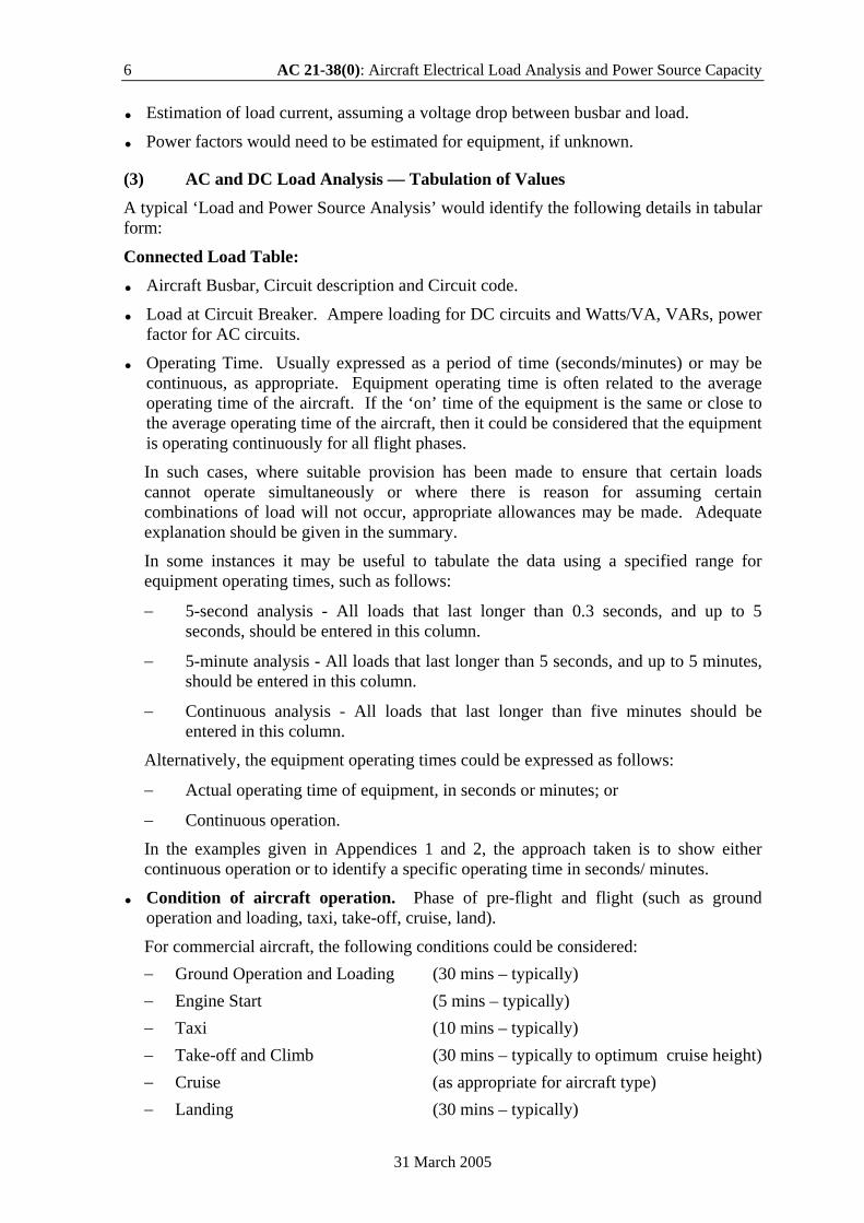
Note: The addition of AC load using kVA and Power Factor is a vector addition and is not an algebraic addition.
kW is the effective power kVA is the apparent power kVAR is the reactive power
Note: Volt-amperes (VA) = (Watts2 + VARs2) ½
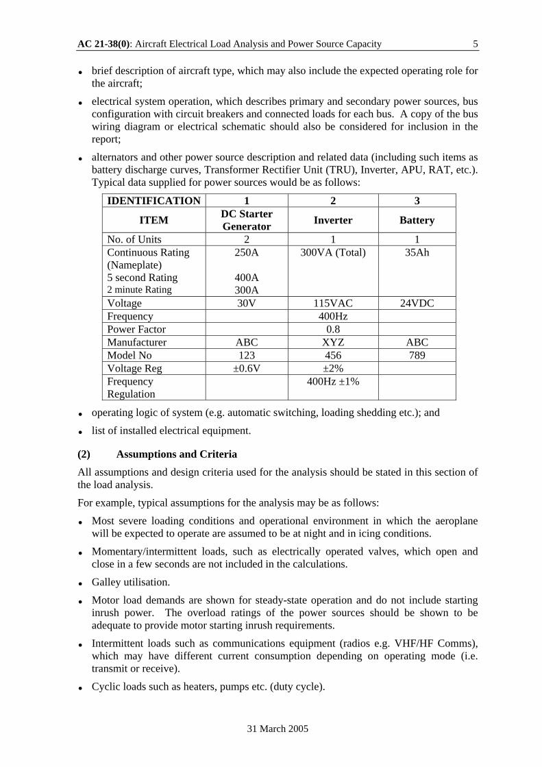
Power Factor (PF) = W/VA, W = watts Power = Voltage x Current x Power Factor (in watts) For sinusoidal supplies a convenient form is Power Factor = cos φ Where φ is the angle of lag or lead between V and I cos φ= kW/kVA therefore kVA = kW/cos φ kVAR = kVA sin φ Total kVA = φ (kW2 + kVAR2) Power Factor of total load = kW/kVA
Worked Example for addition of AC loads with varying Power Factors: Cabin Lighting (capacitive) 20kW at pf of 0.92 leading Flap Motor (inductive) 75 kW at pf of 0.7 lagging Heater (resistive) 45kW at pf of 1.0 Cabin Lighting kVA1 = 20/0.92 = 21.73 kVA Flap Motor kVA2 = 75/0.7 = 107.2 kVA
AC 21-38(0): Aircraft Electrical Load Analysis and Power Source Capacity 9
31 March 2005
Heater kVA3 = 45/1 = 45.0 kVA cos ø1 = 0.92 therefore ø1 = 23o4’ cos ø2 = 0.7 therefore ø2 = 45o34’ kVAR1 = kVA1 sin ø1 = 20 x 0.3918 = 7.836 kVAR kVAR2 = kVA2 sin ø2 = 107.2 x (-)0.7142 = -76.56 kVAR Total kVAR = -68.72 kVAR Total kW =20 + 75 + 45 = 140 kW Total kVA = (kW2 + kVAR2)½ = (1402 + (-68.722)) ½ = 155.96 kVA Power factor of total load = kW/kVA = 140/155.96 = 0.898 lagging
− Average Demand or Average Load (Amps) = Total Current (Amps-Minute) (divided by) Duration of Ground or Flight Phase (Minutes); or Average Demand or Average Load (Volt-Amps, VA or kVA) = Total Current (Amps-Minute) (divided by) Duration of Ground or Flight Phase (Minutes) x Supply Voltage (Volts).
It can be considered that at the start of each operating period (e.g. taxi, take-off, etc.), all equipment that operates during that phase is considered as switched ‘On’, with intermittent loads gradually being switched ‘Off’.
− Intermittent Loads. For intermittent peak loads, root mean square (RMS) values of current should be calculated. Where the currents are continuous, the RMS and the average values will be the same; however, where several intermittent peak loads are spread over a period of time, the RMS value will be more accurate than the average.
Note: RMS is calculated by multiplying the value by 0.707.
Additional Considerations:
− Non-Ohmic or constant power devices (e.g. Inverters). In some cases, the currents drawn at battery voltage (e.g. 20-24VDC) are higher than at the generated voltage (e.g. 28VDC) and will influence the emergency flight conditions on battery. However, for resistive loads, the current drawn will be reduced due to the lower battery voltage.
− System Regulation The system voltage and frequency should be regulated to ensure reliable and continued safe operation of all essential equipment while operating under the normal and emergency conditions, taking into account the voltage drops which occur in the cables and connections to the equipment. The following definitions are provided in RTCA 160D (16.5.2.1) for maximum, nominal, minimum and emergency operations (12 & 28VDC System).
28 VDC system 12VDC System
Maximum 30.3 15.1 Nominal 27.5 13.8 Minimum 22.0 11.0 Emergency 18.0 9.0
10 AC 21-38(0): Aircraft Electrical Load Analysis and Power Source Capacity
31 March 2005
The defined voltage is that supplied at the equipment terminals and allows for variation in the output of the supply equipment (e.g. generators, batteries etc.) as well as voltage drops due to cable and connection resistance.
Note: Voltage drop between busbar and equipment should be considered in conjunction with busbar voltages under normal, abnormal and emergency operating conditions in the estimation of the terminal voltage at the equipment i.e. reduced busbar voltage in conjunction with cable volt drop could lead to malfunction or shutdown of equipment.
− Load Shedding Following the loss of a power source or sources it is considered that a 5-minute period will elapse prior to any manual load shedding by the flight crew, provided that the failure warning system has clear and unambiguous attention-getting characteristics. However, any automatic load shedding can be assumed to take place immediately.
Note: 10 minutes should be used where there is no flashing warning provided to the flight crew.
Where automatic load shedding is provided, a description of the load(s) that will be shed should be provided with any specific sequencing, if applicable.
(4) Emergency or Standby Power Operations Where standby power is provided by non-time limited sources such as a RAT, APU, pneumatic or hydraulic motor; the emergency loads should be listed and evaluated such that the demand does not exceed emergency generator capacity.
Where batteries may be used to provide a time limited emergency supply for certain phases of flight e.g. landing, an analysis of battery capacity should be undertaken. This should be compared with the time necessary for the particular phase of flight (e.g. from slat extension to landing including rollout) where batteries may be utilised in lieu of non-time limited sources.
Battery Condition Calculations
− Battery Duration. Battery endurance can be estimated from either a practical test, which involves applying typical aircraft loads for a period of time or by calculation. It is important that considerations be given to the initial conditions of the aircraft (e.g. condition and state of charge of battery).
Calculation
− An accurate theoretical assessment of the battery performance requires a load analysis to be compiled and the discharge figures checked against the battery manufacturers discharge curves and data sheets.
− The capacity of a battery is:
Rate of discharge (amps) x Time to discharge Normally expressed in ampere-hours, but for a typical load analysis, calculations are usually expressed in amp-mins (i.e. amp-hours x 60). However, this is not a linear function as with heavier discharge currents the discharge time deceases more rapidly so that the power available is less (i.e. reduced efficiency).
AC 21-38(0): Aircraft Electrical Load Analysis and Power Source Capacity 11
31 March 2005
Therefore, in order to make an accurate assessment of battery duration, reference should be made to the manufacturers discharge curves. However, it is recognised that these may not be available and certain assumptions and approximations are provided in the following paragraphs to allow for this case.
Because of the problem of definition of capacity it is important to ensure that all calculations are based on the one-hour rate. Some manufacturers however do not give this on the nameplate and quote the five-hour rate. For these calculations, as a general rule, it may be assumed that the one-hour rate is 85% of the quoted five-hour rate.
Following the generator system failure, and before the pilot has completed the load shedding drills, the battery may be subjected to high discharge currents with a resultant loss of efficiency and capacity on the principle explained in the previous paragraph.
To make allowance for such losses, the calculated power consumed during the pre-loadshed period should be factored by an additional 20% if the average discharge current in amps is numerically more than twice the one-hour rating of the battery.
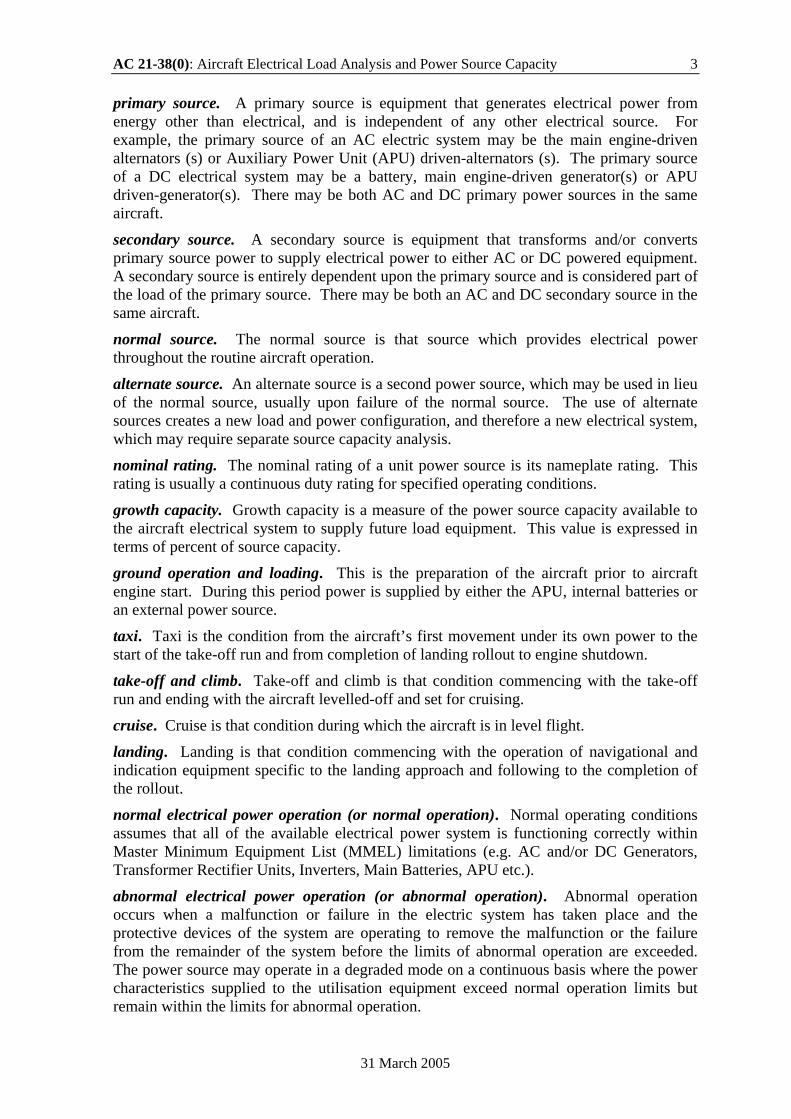
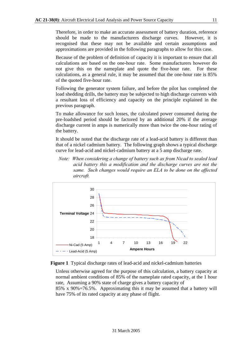
It should be noted that the discharge rate of a lead-acid battery is different than that of a nickel cadmium battery. The following graph shows a typical discharge curve for lead-acid and nickel-cadmium battery at a 5 amp discharge rate.
Note: When considering a change of battery such as from Nicad to sealed lead acid battery this a modification and the discharge curves are not the same. Such changes would require an ELA to be done on the affected aircraft.
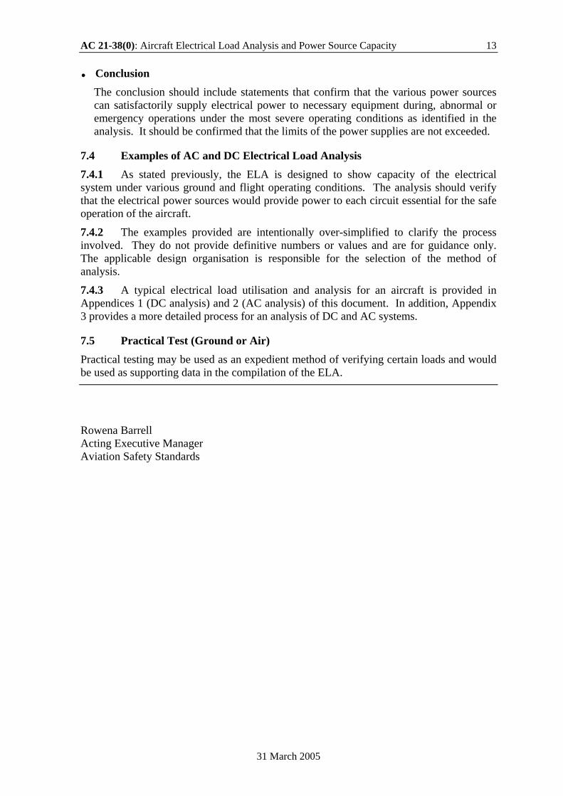
18
20
22
24
26
28
30
1 4 7 10 13 16 19 22
Ampere Hours
Terminal Voltage
Ni-Cad (5 Amp)
Lead-Acid (5 Amp)
Figure 1 Typical discharge rates of lead-acid and nickel-cadmium batteries
Unless otherwise agreed for the purpose of this calculation, a battery capacity at normal ambient conditions of 85% of the nameplate rated capacity, at the 1 hour rate, Assuming a 90% state of charge gives a battery capacity of 85% x 90%=76.5%. Approximating this it may be assumed that a battery will have 75% of its rated capacity at any phase of flight.
12 AC 21-38(0): Aircraft Electrical Load Analysis and Power Source Capacity
31 March 2005
Battery-Charging Current Analysis The charging current for any aircraft battery is based on the total elapsed time from the beginning of the charge, and is calculated using the following formula:
I = A x C where,
I average charging current in Amperes.
A Ampere-hour capacity of the battery, based on the one-hour discharge rate.
C battery-charging factor taken from the battery-charging curve supplied with battery data (graphical data).
An example of how to calculate the battery duration is given below:
− Check the nameplate capacity of the battery and assume 75% is available e.g. 12 amp-hour = 720 amp-mins.
Therefore, 75% is equal to 540 amp-mins.
− (ii) Estimate the normal or pre-load shed cruise consumption (assume worst-case cruise at night). For example, 15 amps (15 amps x 5 mins = 75 amp-mins). This assumes 5 minutes for pilot to shed essential loads following a low voltage warning. Any automatic load shedding can be assumed to be immediate and need not be considered in the pre-load shed calculations.
− (iii) Estimate the minimum cruise load necessary to maintain flight after the generator/alternator has failed e.g. 10 amps.
− (iv) Estimate the consumption required during the landing approach e.g. 20 amps for 5 minutes (100 amp-mins).
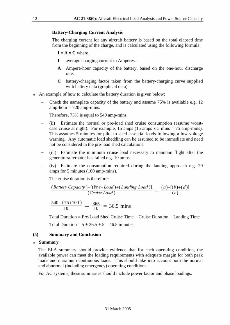
The cruise duration is therefore:
)()]()[()(
)()]()[(Pr)(
cdba
LoadCruiseLoadLandingLoadeCapacityBattery +−+−− =
( )mins36.510
36510
10075540 ==+−
Total Duration = Pre-Load Shed Cruise Time + Cruise Duration + Landing Time
Total Duration = 5 + 36.5 + 5 = 46.5 minutes.
(5) Summary and Conclusion
Summary The ELA summary should provide evidence that for each operating condition, the available power can meet the loading requirements with adequate margin for both peak loads and maximum continuous loads. This should take into account both the normal and abnormal (including emergency) operating conditions.
For AC systems, these summaries should include power factor and phase loadings.
AC 21-38(0): Aircraft Electrical Load Analysis and Power Source Capacity 13
31 March 2005
Conclusion The conclusion should include statements that confirm that the various power sources can satisfactorily supply electrical power to necessary equipment during, abnormal or emergency operations under the most severe operating conditions as identified in the analysis. It should be confirmed that the limits of the power supplies are not exceeded.
7.4 Examples of AC and DC Electrical Load Analysis 7.4.1 As stated previously, the ELA is designed to show capacity of the electrical system under various ground and flight operating conditions. The analysis should verify that the electrical power sources would provide power to each circuit essential for the safe operation of the aircraft.
7.4.2 The examples provided are intentionally over-simplified to clarify the process involved. They do not provide definitive numbers or values and are for guidance only. The applicable design organisation is responsible for the selection of the method of analysis.
7.4.3 A typical electrical load utilisation and analysis for an aircraft is provided in Appendices 1 (DC analysis) and 2 (AC analysis) of this document. In addition, Appendix 3 provides a more detailed process for an analysis of DC and AC systems.
7.5 Practical Test (Ground or Air) Practical testing may be used as an expedient method of verifying certain loads and would be used as supporting data in the compilation of the ELA.
Rowena Barrell Acting Executive Manager Aviation Safety Standards

14 AC 21-38(0): Aircraft Electrical Load Analysis and Power Source Capacity
31 March 2005
Intentionally Left Blank
AC 21-38(0): Aircraft Electrical Load Analysis and Power Source Capacity 15
31 March 2005
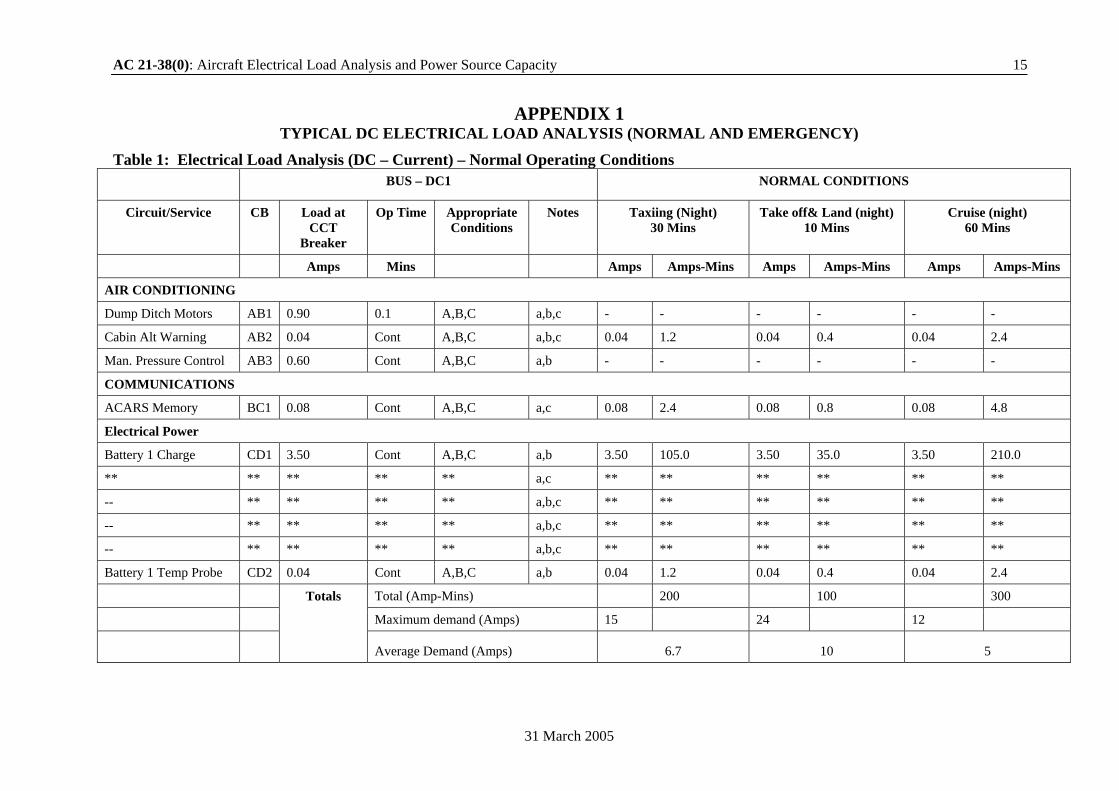
APPENDIX 1 TYPICAL DC ELECTRICAL LOAD ANALYSIS (NORMAL AND EMERGENCY)
Table 1: Electrical Load Analysis (DC – Current) – Normal Operating Conditions
BUS – DC1 NORMAL CONDITIONS
Circuit/Service CB Load at CCT
Breaker
Op Time Appropriate Conditions
Notes Taxiing (Night) 30 Mins
Take off& Land (night) 10 Mins
Cruise (night) 60 Mins
Amps Mins Amps Amps-Mins Amps Amps-Mins Amps Amps-Mins
AIR CONDITIONING
Dump Ditch Motors AB1 0.90 0.1 A,B,C a,b,c - - - - - -
Cabin Alt Warning AB2 0.04 Cont A,B,C a,b,c 0.04 1.2 0.04 0.4 0.04 2.4
Man. Pressure Control AB3 0.60 Cont A,B,C a,b - - - - - -
COMMUNICATIONS
ACARS Memory BC1 0.08 Cont A,B,C a,c 0.08 2.4 0.08 0.8 0.08 4.8
Electrical Power
Battery 1 Charge CD1 3.50 Cont A,B,C a,b 3.50 105.0 3.50 35.0 3.50 210.0
** ** ** ** ** a,c ** ** ** ** ** **
-- ** ** ** ** a,b,c ** ** ** ** ** **
-- ** ** ** ** a,b,c ** ** ** ** ** **
-- ** ** ** ** a,b,c ** ** ** ** ** **
Battery 1 Temp Probe CD2 0.04 Cont A,B,C a,b 0.04 1.2 0.04 0.4 0.04 2.4
Total (Amp-Mins) 200 100 300
Maximum demand (Amps) 15 24 12
Totals
Average Demand (Amps) 6.7 10 5
16 AC 21-38(0): Aircraft Electrical Load Analysis and Power Source Capacity
31 March 2005
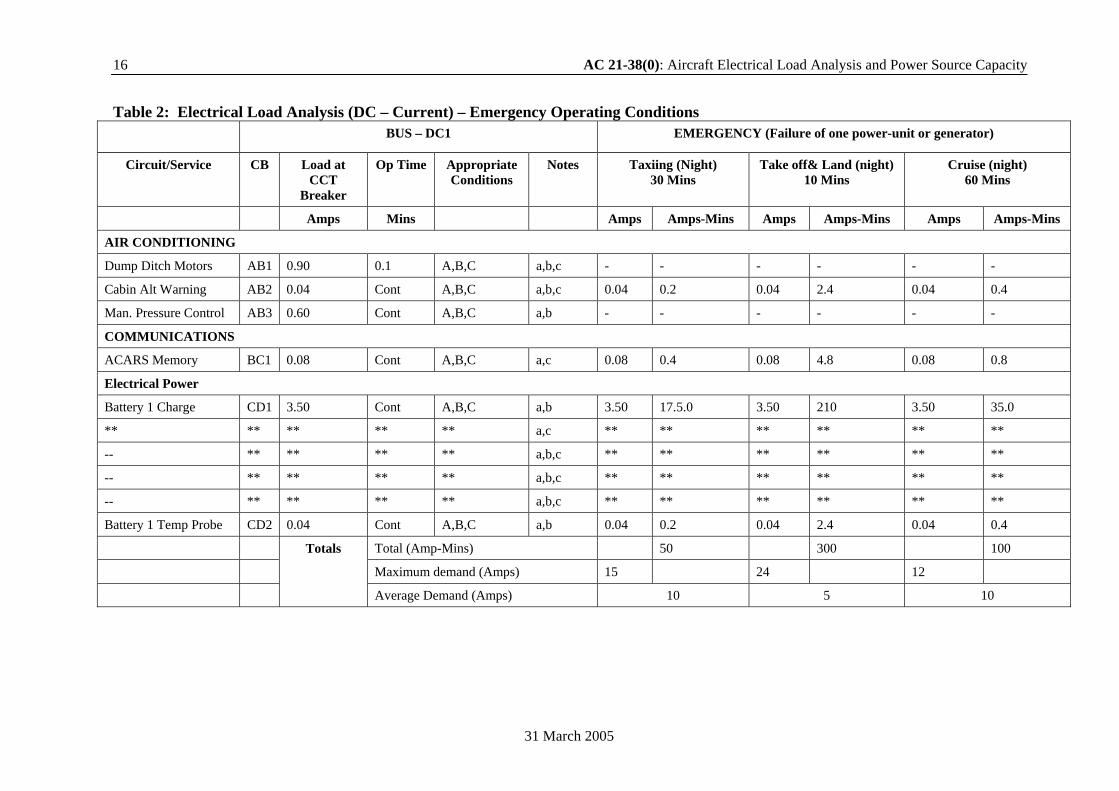
Table 2: Electrical Load Analysis (DC – Current) – Emergency Operating Conditions
BUS – DC1 EMERGENCY (Failure of one power-unit or generator)
Circuit/Service CB Load at CCT
Breaker
Op Time Appropriate Conditions
Notes Taxiing (Night) 30 Mins
Take off& Land (night) 10 Mins
Cruise (night) 60 Mins
Amps Mins Amps Amps-Mins Amps Amps-Mins Amps Amps-Mins
AIR CONDITIONING
Dump Ditch Motors AB1 0.90 0.1 A,B,C a,b,c - - - - - -
Cabin Alt Warning AB2 0.04 Cont A,B,C a,b,c 0.04 0.2 0.04 2.4 0.04 0.4
Man. Pressure Control AB3 0.60 Cont A,B,C a,b - - - - - -
COMMUNICATIONS
ACARS Memory BC1 0.08 Cont A,B,C a,c 0.08 0.4 0.08 4.8 0.08 0.8
Electrical Power
Battery 1 Charge CD1 3.50 Cont A,B,C a,b 3.50 17.5.0 3.50 210 3.50 35.0
** ** ** ** ** a,c ** ** ** ** ** **
-- ** ** ** ** a,b,c ** ** ** ** ** **
-- ** ** ** ** a,b,c ** ** ** ** ** **
-- ** ** ** ** a,b,c ** ** ** ** ** **
Battery 1 Temp Probe CD2 0.04 Cont A,B,C a,b 0.04 0.2 0.04 2.4 0.04 0.4
Total (Amp-Mins) 50 300 100
Maximum demand (Amps) 15 24 12
Totals
Average Demand (Amps) 10 5 10
AC 21-38(0): Aircraft Electrical Load Analysis and Power Source Capacity 17
31 March 2005
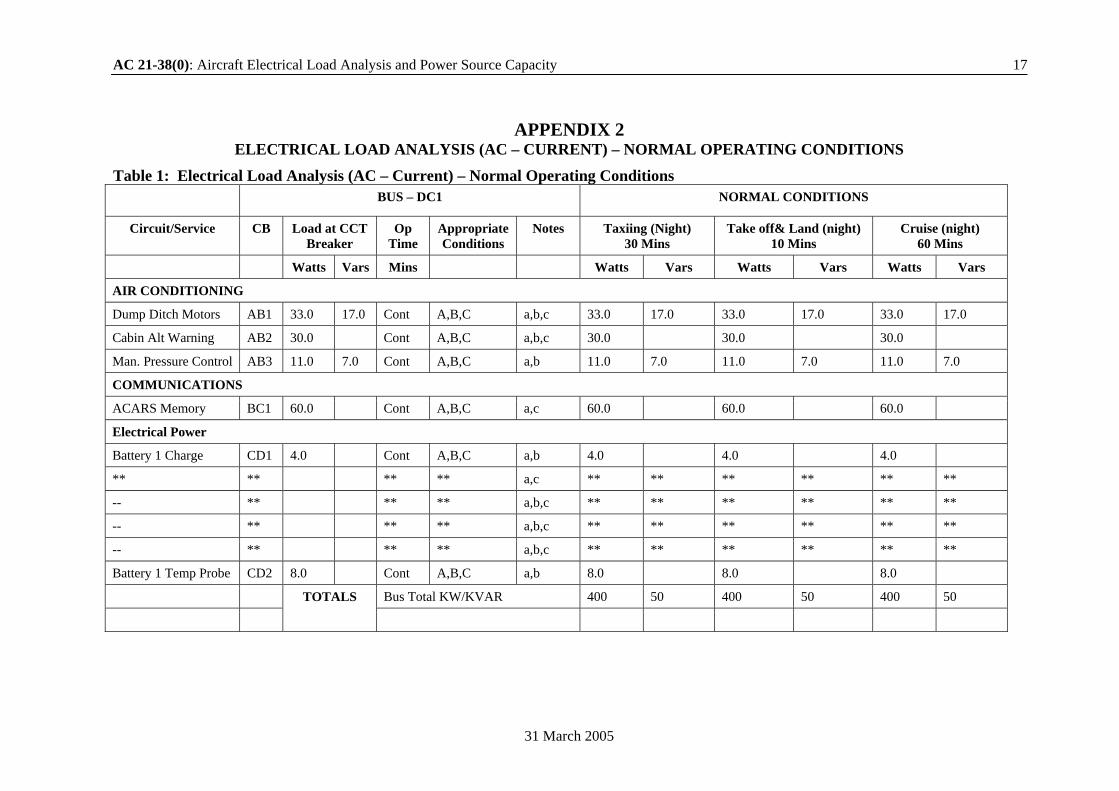
APPENDIX 2 ELECTRICAL LOAD ANALYSIS (AC – CURRENT) – NORMAL OPERATING CONDITIONS
Table 1: Electrical Load Analysis (AC – Current) – Normal Operating Conditions
BUS – DC1 NORMAL CONDITIONS
Circuit/Service CB Load at CCT Breaker
Op Time
Appropriate Conditions
Notes Taxiing (Night) 30 Mins
Take off& Land (night) 10 Mins
Cruise (night) 60 Mins
Watts Vars Mins Watts Vars Watts Vars Watts Vars
AIR CONDITIONING
Dump Ditch Motors AB1 33.0 17.0 Cont A,B,C a,b,c 33.0 17.0 33.0 17.0 33.0 17.0
Cabin Alt Warning AB2 30.0 Cont A,B,C a,b,c 30.0 30.0 30.0
Man. Pressure Control AB3 11.0 7.0 Cont A,B,C a,b 11.0 7.0 11.0 7.0 11.0 7.0
COMMUNICATIONS
ACARS Memory BC1 60.0 Cont A,B,C a,c 60.0 60.0 60.0
Electrical Power
Battery 1 Charge CD1 4.0 Cont A,B,C a,b 4.0 4.0 4.0
** ** ** ** a,c ** ** ** ** ** **
-- ** ** ** a,b,c ** ** ** ** ** **
-- ** ** ** a,b,c ** ** ** ** ** **
-- ** ** ** a,b,c ** ** ** ** ** **
Battery 1 Temp Probe CD2 8.0 Cont A,B,C a,b 8.0 8.0 8.0
Bus Total KW/KVAR 400 50 400 50 400 50
TOTALS
18 AC 21-38(0): Aircraft Electrical Load Analysis and Power Source Capacity
31 March 2005
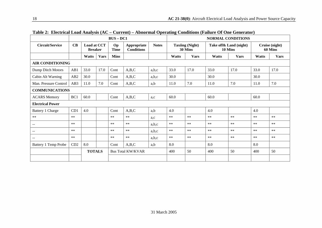
Table 2: Electrical Load Analysis (AC – Current) – Abnormal Operating Conditions (Failure Of One Generator) BUS – DC1 NORMAL CONDITIONS
Circuit/Service CB Load at CCT Breaker
Op Time
Appropriate Conditions
Notes Taxiing (Night) 30 Mins
Take off& Land (night) 10 Mins
Cruise (night) 60 Mins
Watts Vars Mins Watts Vars Watts Vars Watts Vars
AIR CONDITIONING
Dump Ditch Motors AB1 33.0 17.0 Cont A,B,C a,b,c 33.0 17.0 33.0 17.0 33.0 17.0
Cabin Alt Warning AB2 30.0 Cont A,B,C a,b,c 30.0 30.0 30.0
Man. Pressure Control AB3 11.0 7.0 Cont A,B,C a,b 11.0 7.0 11.0 7.0 11.0 7.0
COMMUNICATIONS
ACARS Memory BC1 60.0 Cont A,B,C a,c 60.0 60.0 60.0
Electrical Power
Battery 1 Charge CD1 4.0 Cont A,B,C a,b 4.0 4.0 4.0
** ** ** ** a,c ** ** ** ** ** **
-- ** ** ** a,b,c ** ** ** ** ** **
-- ** ** ** a,b,c ** ** ** ** ** **
-- ** ** ** a,b,c ** ** ** ** ** **
Battery 1 Temp Probe CD2 8.0 Cont A,B,C a,b 8.0 8.0 8.0
Bus Total KW/KVAR 400 50 400 50 400 50
TOTALS
AC 21-38(0): Aircraft Electrical Load Analysis and Power Source Capacity 19
31 March 2005
APPENDIX 3 ELECTRICAL SYSTEMS
Table 1: DC System: 28v Conditions of Aircraft operations Aircraft – Two Power Units Flight Duration: 3 Hours
Electrical System: Earth Return DC 28V; 2 Generators 3kW at Cruise, 1.5 kW at taxiing;
1 battery 37Ah (Ten-Hour Rate) Normal Abnormal (Failure of one power-unit or generator)
1 2 3 4 5 6 7 8 9 10 11 12 13 14 15 Item Service Units
per A/C
Units op simult
Current at 95% volts (amp)
Drop in line volts (volt)
Op Time (min)
No of Times ON
Taxi (night) 30 mins
Take-off and Land (night) 10 mins
Cruise (day) 60 mins
Cruise (night) 60 mins
Cruise (night) prior to load shed 5 mins
Cruise (night) after load shed 60 mins
Land (night) 10 mins
amp amp-min
amp amp-min
amp amp-min
amp amp-min
amp amp-min
amp amp-min
amp amp-min
1 Motor, Flaps 1 1 120 6 15s 1 120 30 120 30 120 30 2 Prop, feather 2 1 100 5 15s 1 100 25 100 25 3 Motor, U/C 1 1 160 8 30s 1 160 80 4 Trim tab motor 3 1 4 1 1 3 4 12 4 12 4 36 4 36 4 12 4 36 4 12 5 Cowl flaps 2 2 10 2 3 2 20 60 20 60 20 60 20 60 20 60 20 60 20 60 6 Water heater 1 1 25 2 10 2 25 500 25 500 25 125 7 Galley 1 1 40 2 15 1 40 600 40 600 40 200 8 Radio Trans 1 1 20 2 15 1 20 300 20 200 20 300 20 300 20 100 20 300 20 200 9 Fuel Trans pump 2 1 10 1 15 1 10 150 150 10 10 150 10 Motor de-icing 2 1 5 1.5 Cont 1 5 50 5 75 5 75 5 25 5 75 5 50 11 Prop. Auto Ctl 2 2 5 2 Cont Cont 10 300 10 100 10 600 10 600 10 50 10 600 10 100 12 Fuel Boost pump 2 2 10 0.5 Cont Cont 20 200 20 1200 20 1200 20 100 20 1200 20 200 13 Engine Inst. 12 12 1 0.5 Cont Cont 12 360 12 120 12 720 12 720 12 60 12 720 12 120
14(a) Int. Lights (essential) 5 5 1 0.5 Cont Cont 5 150 5 50 5 300 5 25 5 300 5 50
14(b) Int. Lights (non-essential) 10 10 1 0.5 Cont Cont 10 300 10 100 10 600 10 50
15 Nav. Lights 5 5 1 0.5 Cont Cont 5 150 5 50 5 300 5 25 5 300 5 50 16 Vent Fans 6 6 5 1.5 Cont Cont 30 900 5 50 5 300 5 300 5 25 17 Refrigerator 1 1 15 2 Cont Cont 15 450 15 150 15 900 15 900 15 75 18 Auto pilot Inv. 1 1 5 1 Cont Cont 5 300 5 300 5 25 19 Inst. (flight) inv 1 1 5 1 Cont Cont 5 150 5 50 5 30 5 30 5 25 5 300 5 50 20 Radio Receiver 1 1 5 1 Cont Cont 5 150 5 50 5 300 5 300 5 25 5 300 5 50 21 Intercomm 1 1 5 1 Cont Cont 5 150 5 50 5 300 5 300 5 25 5 300 5 50 Total (amp-min) 3462 1427 6641 7841 1057 4641 1102 Maximum Demand (amp) 266 526 206 226 126 396 Average Demand (amp) 115 143 111 131 77 110
20 AC 21-38(0): Aircraft Electrical Load Analysis and Power Source Capacity
31 March 2005
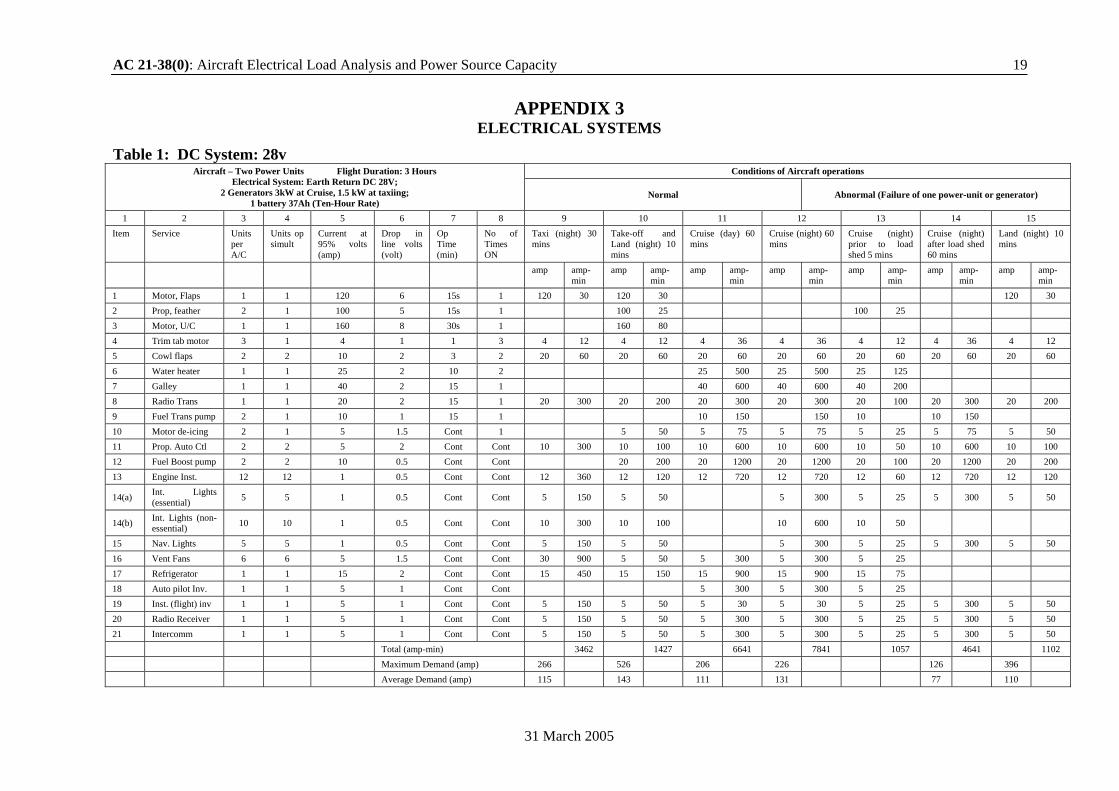
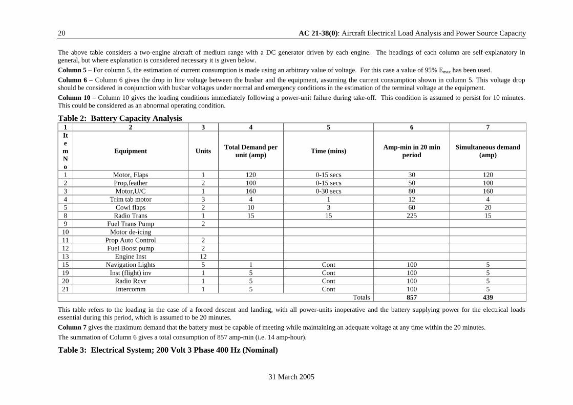
The above table considers a two-engine aircraft of medium range with a DC generator driven by each engine. The headings of each column are self-explanatory in general, but where explanation is considered necessary it is given below. Column 5 – For column 5, the estimation of current consumption is made using an arbitrary value of voltage. For this case a value of 95% Emax has been used. Column 6 – Column 6 gives the drop in line voltage between the busbar and the equipment, assuming the current consumption shown in column 5. This voltage drop should be considered in conjunction with busbar voltages under normal and emergency conditions in the estimation of the terminal voltage at the equipment. Column 10 – Column 10 gives the loading conditions immediately following a power-unit failure during take-off. This condition is assumed to persist for 10 minutes. This could be considered as an abnormal operating condition.
Table 2: Battery Capacity Analysis 1 2 3 4 5 6 7 Item No
Equipment Units Total Demand per unit (amp) Time (mins) Amp-min in 20 min
period Simultaneous demand
(amp)
1 Motor, Flaps 1 120 0-15 secs 30 120 2 Prop,feather 2 100 0-15 secs 50 100 3 Motor,U/C 1 160 0-30 secs 80 160 4 Trim tab motor 3 4 1 12 4 5 Cowl flaps 2 10 3 60 20 8 Radio Trans 1 15 15 225 15 9 Fuel Trans Pump 2
10 Motor de-icing 11 Prop Auto Control 2 12 Fuel Boost pump 2 13 Engine Inst 12 15 Navigation Lights 5 1 Cont 100 5 19 Inst (flight) inv 1 5 Cont 100 5 20 Radio Rcvr 1 5 Cont 100 5 21 Intercomm 1 5 Cont 100 5
Totals 857 439
This table refers to the loading in the case of a forced descent and landing, with all power-units inoperative and the battery supplying power for the electrical loads essential during this period, which is assumed to be 20 minutes. Column 7 gives the maximum demand that the battery must be capable of meeting while maintaining an adequate voltage at any time within the 20 minutes. The summation of Column 6 gives a total consumption of 857 amp-min (i.e. 14 amp-hour). Table 3: Electrical System; 200 Volt 3 Phase 400 Hz (Nominal)
AC 21-38(0): Aircraft Electrical Load Analysis and Power Source Capacity 21
31 March 2005
Item No
Service No of Units
Units Op Simult Volt-amp per Unit Op Time
(min) Load Dist Normal Operations
Peak Normal Normal supply
Stnadby Supplies
Engine Start Taxi (night) Take0ff or land (night) Cruise (night)
1st 2nd A P S A P S A P S 1 2 3 4 5 6 7 8 9 10 11 12 13 14 15 16 17 18 19
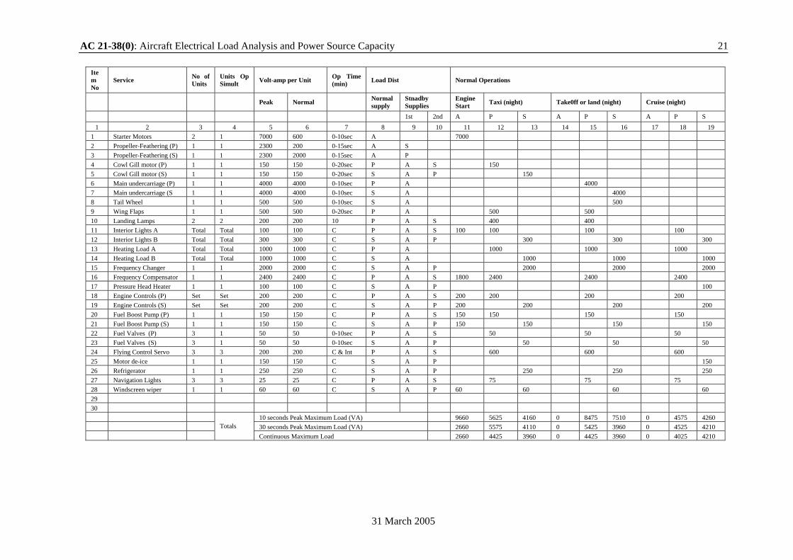
1 Starter Motors 2 1 7000 600 0-10sec A 7000 2 Propeller-Feathering (P) 1 1 2300 200 0-15sec A S 3 Propeller-Feathering (S) 1 1 2300 2000 0-15sec A P 4 Cowl Gill motor (P) 1 1 150 150 0-20sec P A S 150 5 Cowl Gill motor (S) 1 1 150 150 0-20sec S A P 150 6 Main undercarriage (P) 1 1 4000 4000 0-10sec P A 4000 7 Main undercarriage (S 1 1 4000 4000 0-10sec S A 4000 8 Tail Wheel 1 1 500 500 0-10sec S A 500 9 Wing Flaps 1 1 500 500 0-20sec P A 500 500 10 Landing Lamps 2 2 200 200 10 P A S 400 400 11 Interior Lights A Total Total 100 100 C P A S 100 100 100 100 12 Interior Lights B Total Total 300 300 C S A P 300 300 300 13 Heating Load A Total Total 1000 1000 C P A 1000 1000 1000 14 Heating Load B Total Total 1000 1000 C S A 1000 1000 1000 15 Frequency Changer 1 1 2000 2000 C S A P 2000 2000 2000 16 Frequency Compensator 1 1 2400 2400 C P A S 1800 2400 2400 2400 17 Pressure Head Heater 1 1 100 100 C S A P 100 18 Engine Controls (P) Set Set 200 200 C P A S 200 200 200 200 19 Engine Controls (S) Set Set 200 200 C S A P 200 200 200 200 20 Fuel Boost Pump (P) 1 1 150 150 C P A S 150 150 150 150 21 Fuel Boost Pump (S) 1 1 150 150 C S A P 150 150 150 150 22 Fuel Valves (P) 3 1 50 50 0-10sec P A S 50 50 50 23 Fuel Valves (S) 3 1 50 50 0-10sec S A P 50 50 50 24 Flying Control Servo 3 3 200 200 C & Int P A S 600 600 600 25 Motor de-ice 1 1 150 150 C S A P 150 26 Refrigerator 1 1 250 250 C S A P 250 250 250 27 Navigation Lights 3 3 25 25 C P A S 75 75 75 28 Windscreen wiper 1 1 60 60 C S A P 60 60 60 60 29 30 10 seconds Peak Maximum Load (VA) 9660 5625 4160 0 8475 7510 0 4575 4260 30 seconds Peak Maximum Load (VA) 2660 5575 4110 0 5425 3960 0 4525 4210
Totals Continuous Maximum Load 2660 4425 3960 0 4425 3960 0 4025 4210
22 AC 21-38(0): Aircraft Electrical Load Analysis and Power Source Capacity
31 March 2005
Table 4: Electrical System: 200 Volt 3 Phase 400 Hz (Nominal) Item No Service No of
Units
Units Op Similt
Volt-amp per Unit
Op Time (min)
Load Distribution Abnormal Operations Emergency Operation
Port power-unit and alternator off
Starboard power-unit and alternator off Auxiliary Power Unit (APU) Both power
units off Peak Normal Normal Supply
Standby Supply Take off or land
(night) Cruise (night)
Take off or land (night)
Cruise (night) Taxi (night) Take-off or
land (night) Forced descent (night and land
1st 2nd S A S P A P P S P S A 1 2 3 4 5 6 7 8 9 10 11 12 13 14 15 16 17 18 19 20 21
1 Starter Motors 2 1 7000 600 0-10sec A 2 Propeller-Feathering (P) 1 1 2300 200 0-15sec A S 2300 3 Propeller-Feathering (S) 1 1 2300 2000 0-15sec A P 2300 2300 4 Cowl Gill motor (P) 1 1 150 150 0-20sec P A S 150 5 Cowl Gill motor (S) 1 1 150 150 0-20sec S A P 150 6 Main undercarriage (P) 1 1 4000 4000 0-10sec P A 4000 4000 4000 7 Main undercarriage (S 1 1 4000 4000 0-10sec S A 4000 4000 4000 8 Tail Wheel 1 1 500 500 0-10sec S A 500 500 500 9 Wing Flaps 1 1 500 500 0-20sec P A 500 500 500 500 500 10 Landing Lamps 2 2 200 200 10 P A S 400 400 400 400 400 11 Interior Lights A Total Total 100 100 C P A S 100 100 100 100 100 100 100 12 Interior Lights B Total Total 300 300 C S A P 300 300 300 300 300 300 13 Heating Load A Total Total 1000 1000 C P A 1000 1000 1000 1000 1000 14 Heating Load B Total Total 1000 1000 C S A 1000 1000 100 1000 1000 15 Frequency Changer 1 1 2000 2000 C S A P 2000 2000 2000 2000 2000 2000 200 16 Frequency Compensator 1 1 2400 2400 C P A S 1800 2400 2400 2400 2400 2400 1800 17 Pressure Head Heater 1 1 100 100 C S A P 100 100 100 18 Engine Controls (P) Set Set 200 200 C P A S 200 200 200 200 200 19 Engine Controls (S) Set Set 200 200 C S A P 200 200 200 200 200 20 Fuel Boost Pump (P) 1 1 150 150 C P A S 150 150 150 150 150 21 Fuel Boost Pump (S) 1 1 150 150 C S A P 150 150 150 150 150 22 Fuel Valves (P) 3 3 50 50 0-10sec P A S 50 50 50 50 50 50 50 23 Fuel Valves (S) 3 1 50 50 0-10sec S A P 50 50 50 50 50 50 50 24 Flying Control Servo 3 1 200 200 C & Int P A S 600 600 600 600 600 600 600 25 Motor de-ice 1 1 150 150 C S A P 150 150 150 26 Refrigerator 1 1 250 250 C S A P 250 250 250 250 250 250 27 Navigation Lights 3 3 25 25 C P A S 75 75 75 75 75 75 75 28 Windscreen wiper 1 1 60 60 C S A P 60 60 60 60 60 60 60 29 30 10 seconds Peak Maximum Load (VA) 7510 9825 9785 8475 9460 9785 5625 4160 8475 7510 6585 30 seconds Peak Maximum Load (VA) 3960 6775 9685 5425 5910 9685 5575 4110 5425 3960 6485
Totals Continuous Maximum Load 3960 3475 6885 4425 3610 6885 4425 3960 4425 3960 5485
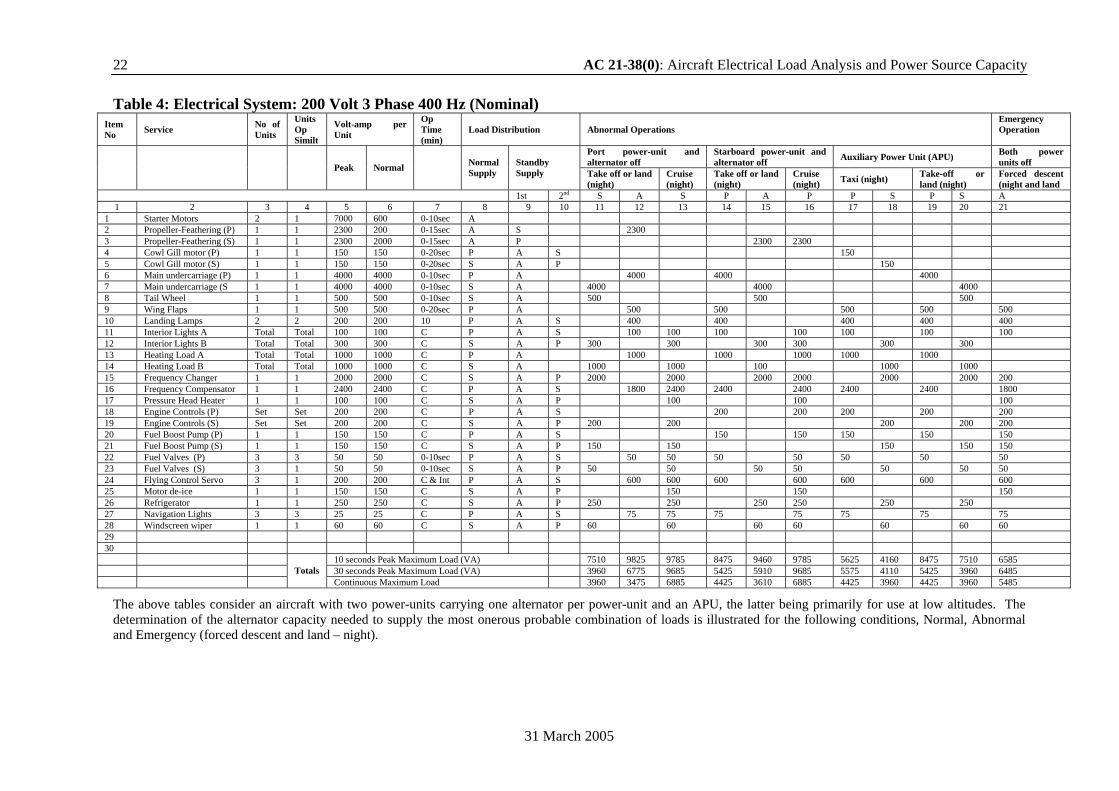
The above tables consider an aircraft with two power-units carrying one alternator per power-unit and an APU, the latter being primarily for use at low altitudes. The determination of the alternator capacity needed to supply the most onerous probable combination of loads is illustrated for the following conditions, Normal, Abnormal and Emergency (forced descent and land – night).