Embed Size (px)
Citation preview

Sagnac Effect:The Ballistic Interpretation
A. A. [email protected]
Abstract:
The primary objective, in the present investigation, is to calculate time-of-flight differences between the co-rotating beam and the counter-rotating beam, over the optical square loop of the Sagnac interferometer, in accordance with the assumption of velocity of light dependent upon the velocity of the light source; and then to compare the obtained results to the computed time-of-flight differences between the same two beams, based on the assumption of velocity of light independent of the velocity of the light source. And subsequently, on the basis of the numerical results of those calculations, it's concluded that, because of the presence of ballistic beaming, the Sagnac interferometer, and rotating interferometers, generally, are incapable of providing any conclusive experimental evidence for or against either one of the two diametrically opposed assumptions, under investigation. In the 1913 Sagnac experiment, for instance, the numerical values of the time-of-flight differences, as predicted by these two propositions, differ from each other by no more than an infinitesimal fraction equal to about 10-30 of a second.

Keywords:
Sagnac effect; fringe shift; constant speed of light; angular velocity; ballistic speed of light; headlight effect; rotating interferometer; ballistic beaming.
Introduction:
Undoubtedly, one of the most common oversights in the calculations of Sagnac effect and related phenomena, on the basis of the proposition of ballistic velocity of light, in the published literature, is the incorrect assumption that light traveling at the velocity of c and light traveling at the velocity resultant of c & v must always have together and share in harmony the same exact light path.
But it's quite clear that, in accordance with the assumption of velocity of light dependent upon the velocity of the light source at the time of emission, if light is emitted, in the reference frame of a moving light source, with its muzzle speed of c and at an angle θ with respect to the velocity vector of the light source v, then, as illustrated in Figure #1 below, the emitted light must bend in the forward direction with respect to the velocity vector of the light source by an angle of Δθ and travel along the new direction of (θ - Δθ) at the velocity resultant of c'; except in the case of θ equal to 0o and the case of θ equal to 180o , in both of which Δθ is always equal to zero.
Figure #1: Ballistic Beaming & Velocity Resultant of Light
v
cc'
θ
Δθ
Δθ
θ
c'
c
v
[A] [B]

And this sort of bending of emitted light implies, necessarily, that, within the framework of the elastic-impact emission theory, neither the co-rotating beam, nor the counter-rotating beam, in the 1913 Sagnac experiment and similar experiments, can possibly travel along the specified optical loop of the rotating Sagnac interferometer.
The crucial question now, therefore, is this:
Is it mathematically possible, based on the given specifications of the Sagnac interferometer, to determine, within the framework of the elastic-impact emission theory, the length of each optical loop for the two beams, under investigation?
It's certainly, possible to determine the length of the two ballistic loops, in all cases, in which the lengthof the optical loop, for light traveling at c, and its angle of incidence are among the listed specifications of the Sagnac interferometer.
Let L denote the length of the stationary path between each pair of mirrors; and let α denote the angleof incidence, when the Sagnac interferometer is at rest.
And let L' denote the length of the ballistic path between the same pair of mirrors, when the Sagnac interferometer is rotating.
By definition, the angle Δθ is always between L and L'.
And furthermore, the sine of the angle Δθ can be calculated, through the application of the trigonometric law of sines to the velocity triangle in Figure #1 above, in accordance with the followingequation:
where v is the tangential velocity of the light source; and c' is the velocity resultant of light as computed by using this equation:
2 2 2 cosc c v cv q¢ = + +
2
2
sin sin sin
1 2 cos
v v c
c v vc c
q q q
q
D = =¢
+ +

in which θ is the angle made by the initial direction of light to the velocity vector of the light source.
And therefore, from the geometry illustrated in Figure #2 below:
We can obtain, through the use of the trigonometric law of sines, the following mathematical formula for computing the ballistic length L' between each pair of mirrors, within the optical Sagnac loop, in the case of the co-rotating beam:
as well as in the case of the counter-rotating beam:
Figure #2: Path L & Path L'
45o
N
S
C
B
L'L
Δθ
45o+Δθ
( )( )sin 45
sin 45
o
oL L
q
æ ö¢ ç ÷=
ç ÷+ Dè ø
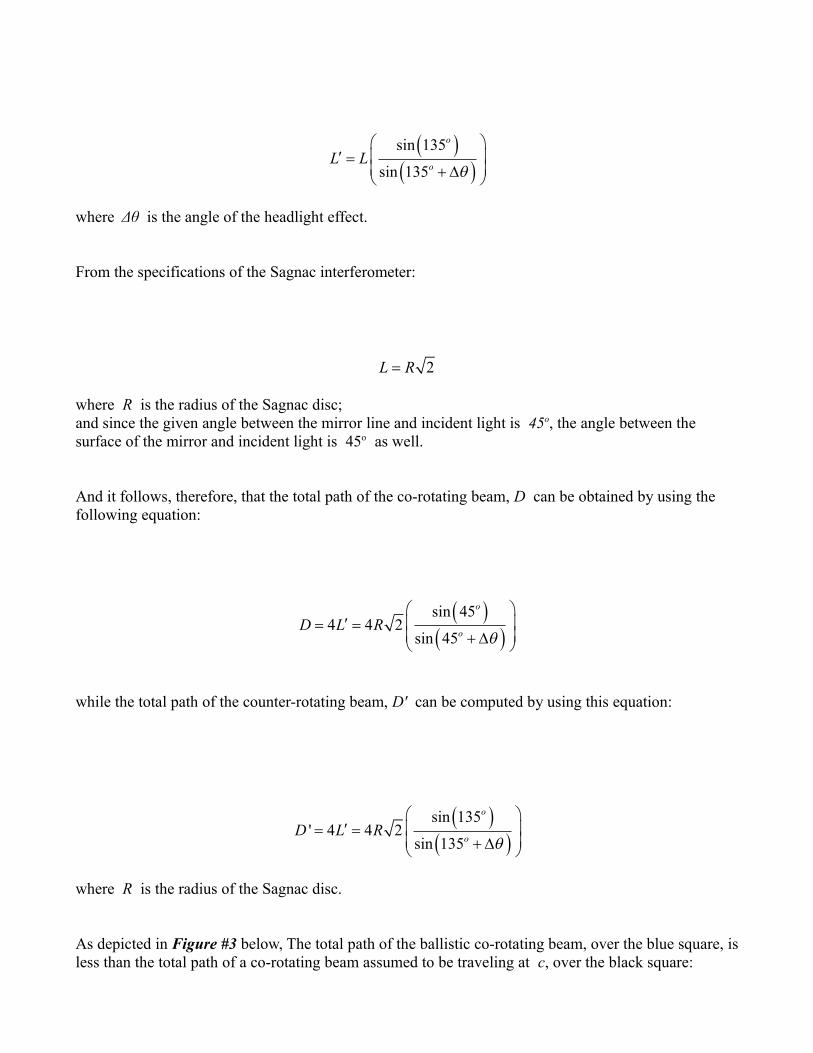
where Δθ is the angle of the headlight effect.
From the specifications of the Sagnac interferometer:
where R is the radius of the Sagnac disc; and since the given angle between the mirror line and incident light is 45o, the angle between the surface of the mirror and incident light is 45o as well.
And it follows, therefore, that the total path of the co-rotating beam, D can be obtained by using the following equation:
while the total path of the counter-rotating beam, D' can be computed by using this equation:
where R is the radius of the Sagnac disc.
As depicted in Figure #3 below, The total path of the ballistic co-rotating beam, over the blue square, isless than the total path of a co-rotating beam assumed to be traveling at c, over the black square:
( )( )sin 135
' 4 4 2sin 135
o
oD L R
q
æ ö¢ ç ÷= =
ç ÷+ Dè ø
( )( )sin 45
4 4 2sin 45
o
oD L R
q
æ ö¢ ç ÷= =
ç ÷+ Dè ø
2L R=
( )( )sin 135
sin 135
o
oL L
q
æ ö¢ ç ÷=
ç ÷+ Dè ø

And that is because:
( ) ( )0 0sin 45 sin 45q+ D >
FIGURE #3: The Relative Sizes of the Three Optical Loops
Co-rotating Beam
Counter-rotating Beam
S
D
M1
M2
M3
P
N

By contrast, the total path of the ballistic counter-rotating beam, over the red square, is greater than the total path of a co-rotating beam assumed to be traveling at c, over the black square. And that is also because:
For example, in the 1913 Sagnac experiment, the area of the enclosed optical loop for the co-rotating beam and the counter-rotating beam, both assumed to be traveling at c, is 0.86 m2; on a disc making 2 rotations per second.
By calculating the total path, D, for the co-rotating ballistic beam, through the use of this equation:
where R is the radius of the Sagnac disc; and then subtracting D from the total path, Dc , for light assumed to be traveling at c, we obtain the following numerical result:
which is equal to about 45.898 nanometers.
And likewise, by calculating the total path, D', for the counter-rotating ballistic beam, through the use of the following equation:
where R is the radius of the Sagnac disc; and then subtracting Dc, for light assumed to be traveling at c, from the total path, D', we obtain this numerical result:
( ) ( )0 0sin 135 sin 135q+ D <
( )( )sin 45
4 4 2sin 45
o
oD L R
q
æ ö¢ ç ÷= =
ç ÷+ Dè ø
( )( )sin 135
' 4 4 2sin 135
o
oD L R
q
æ ö¢ ç ÷= =
ç ÷+ Dè ø
84.5898419499 10 mcD D D -D = - = ´

which is equal to about 45.898 nanometers.
On the face of it, a 45.898 - nanometer difference, in the path length, seems, at first glance, to be extremely tiny and insignificant.
But believe it or not, in the 1913 Sagnac experiment, the entire time difference of about:
is due to a difference, in the path length between the co-rotating beam and the counter-rotating beam, equal to about 91.797 nanometers .
It's imperative, therefore, to calculate the predicted time differences, on the assumption of ballistic velocity of light, only along the ballistic paths of light assumed to be traveling at the ballistic velocity resultant of c'; and not along the non-ballistic paths of light taken for granted to be traveling at the constant and non-additive velocity of c; otherwise, the computed predictions, in this particular case, are bound to be partially or totally inaccurate.
1. The Sagnac Interferometer:
Although several specifications of the Sagnac interferometer play no significant role at all, within the framework of the classical wave theory, some of those specifications, such as the orientation of the mirror lines with respect to the velocity vectors of the mirrors, for example, can become extremely important in any calculations of the Sagnac effect, on the basis of the elastic-impact emission theory.
As illustrated in Figure #4 below, the original Sagnac interferometer consists of three plane mirrors, M1, M2, M3, and a beam splitter P, which form together a square loop on the top of a rotating disc, along with the light source S and the detector D.
A coherent beam of light is emitted, by the light source S, at an angle of 45o with respect to the vector of its tangential velocity v, towards the beam splitter P. The initial beam strikes the beam splitter P at an angle of 225o with respect to the normal line to its surface as well as with respect to the vector of its tangential velocity. The incident beam is split by the beam splitter P into two beams that traverse the same optical square in opposite directions. The co-rotating beam is transmitted by the beam splitter
-163.062 10 secondsTD = ´
-84.5898419499 10 mcD D D¢D = - = ´

P, at an angle of 45o along the periphery of the optical square PM1M2M3P towards the detector D. At the same time, the counter-rotating beam is reflected by the beam splitter P, with respect to the vector of its tangential velocity, at an angle of 135o along the periphery of the optical square PM3M2M1P towards the same detector D.
The above arrangement of the Sagnac interferometer has the following characteristics:
• The normal line to the surface of the beam splitter P coincides with the vector of its tangential velocity. And consequently, according to the rules of reflection from moving mirrors, as applied in accordance with the elastic-impact emission theory, the beam splitter P can actively alter the magnitude and the direction of the velocity of incident light.
• The normal lines to the surfaces of the three mirrors – M1, M2, & M3 – are at right angles to the vectors of their tangential velocities. And therefore, those three mirrors, according to the ballistic assumption, do not change the numerical magnitude of the velocity of incident light.
Figure #4: Sagnac Interferometer
M1
D
S
M3
M2P ω
N
Co-rotating Beam
Counter-rotating Beam
v R
R

• The locations of the light source S, the beam splitter P, and the detector D form a right angle with each other, and have, practically, the same tangential velocity.
• The length of each of the four sides of the optical square is equal to L:
where R is the radius of the Sagnac disc.
• When the interferometer is at rest relative to the laboratory, no fringe shift is registered by the detector D.
• When the interferometer is rotating with an angular velocity ω with respect to the laboratory, afringe shift, in direct proportion to the value of angular velocity, is registered by the detector D.
• The observed fringe shift is directly proportional to the difference between the travel time of theco-rotating beam and the travel time of the counter-rotating beam, as computed by Georges Sagnac himself, on the assumption of velocity of light independent of the velocity of the light source, as defined and applied within the framework of the classical wave theory [Ref. #8.a & 8.b].
And therefore, in the current investigation, the differences in travel time between those two beams will be computed on the assumption of velocity of light independent of the velocity of the light source, according to the classical wave theory; and then the same time differences will be recalculated on the assumption of velocity of light dependent upon the velocity of the light source at the time of emission, as defined and applied within the framework of the elastic-impact emission theory.
2. The Prediction of the Classical Wave Theory:
According to the basic assumption of the classical wave theory, upon which Georges Sagnac based his calculations, the velocity of light, in vacuum, is independent of the velocity of the light source at the time of emission.
2L R=

And therefore, only the relative velocity of incident light, with respect to the velocity vectors of the various parts of the experimental apparatus, can play a major role in any calculations, on the basis of the classical wave theory, concerning the Sagnac effect.
Let ω stand for the angular velocity of the rotating disc; and hence, at any point located at a distance equal to the radius R from the center of rotation:
where v is the tangential velocity at the periphery of the rotating disc.
And let L stand for the length of each side of the optical square, on the rotating disc:
where R is the radius of the Sagnac disc.
And let Tcor denote the flight time of the co-rotating beam over the optical path PM1M2M3P; and let Tcount denote the flight time of the counter-rotating beam over the optical path PM3M2M1P.
A. The Travel Time of the Co-rotating Beam:
The co-rotating beam is transmitted by the beam splitter P at a 45o angle towards the mirror M1; and reflected by the mirror M1 at the same angle towards the mirror M2; and by the mirror M2 towards the mirror M3; and then by the mirror M3 towards the beam splitter P; and, finally, transmitted by the beamsplitter P towards the detector D to be combined with the counter-rotating beam.
And accordingly, the total flight time of the co-rotating beam, over the square PM1M2M3P, can be obtained by using the following equation:
v Rw=
2L R=
4 *cos(45 ) 4
*cos(45 )
ocor
cor o
L T v LT
c c v
é ù+ ë û= =-

where Tcor is the total travel time of the co-rotating beam.
B. The Travel Time of the Counter-rotating Beam:
The counter-rotating beam is reflected by the beam splitter P at a 135o angle towards the mirror M3; and reflected by the mirror M3 at the same angle towards the mirror M2; and by the mirror M2 towards the mirror M1; and by the mirror M1 towards the beam splitter P; and, finally, reflected by the beam splitter P towards the detector D to be combined with the co-rotating beam.
And correspondingly, the total flight time of the counter-rotating beam, over the square PM3M2M1P, can be obtained by using the following equation:
where Tcount is the total travel time of the co-rotating beam.
C. The Predicted Difference in Travel Time:
It follows, therefore, that, on the assumption of velocity of light independent of the velocity of the light source at the time of emission, the predicted time difference between the arrival of the co-rotating beamand the arrival of the counter-rotating beam at the Sagnac detector D, can be computed through the use of this equation:
where ΔT is the predicted time difference; and v:
4 *cos(135 ) 4
*cos(135 )
ocor
count o
L T v LT
c c v
é ù+ ë û= =-
( ) ( )( ) ( )2 2 2
cos 458
1 cos 45
o
cor count o
v cLT T T
c v c
é ùê úD = - =-ê úë û
v Rw=

where v is the tangential velocity; and ω is the angular velocity; and L:
where R is the radius of the rotating disc; and:
Since, in the 1913 Sagnac experiment, the enclosed area by the light path, A is:
and the angular velocity of the rotating disc, ω is:
[Ref. #2], and hence:
The classical wave theory predicts, in this case, the following numerical value for the time difference between the travel time of the co-rotating beam and the travel time of the counter-rotating beam, over the optical loop of the Sagnac interferometer:
Clearly, the Sagnac interferometer has a remarkable degree of sensitivity and extraordinary ability for sensing and measuring such extremely minute and infinitesimally small time differences.
The time differences between the flight time of the co-rotating beam and the flight time of the counter-
2L R=
2086 mA =
2 Hzw =
( ) ( )cos 135 cos 45o o= -
-163.062 10 secondsTD = ´
4 rad/sw p=
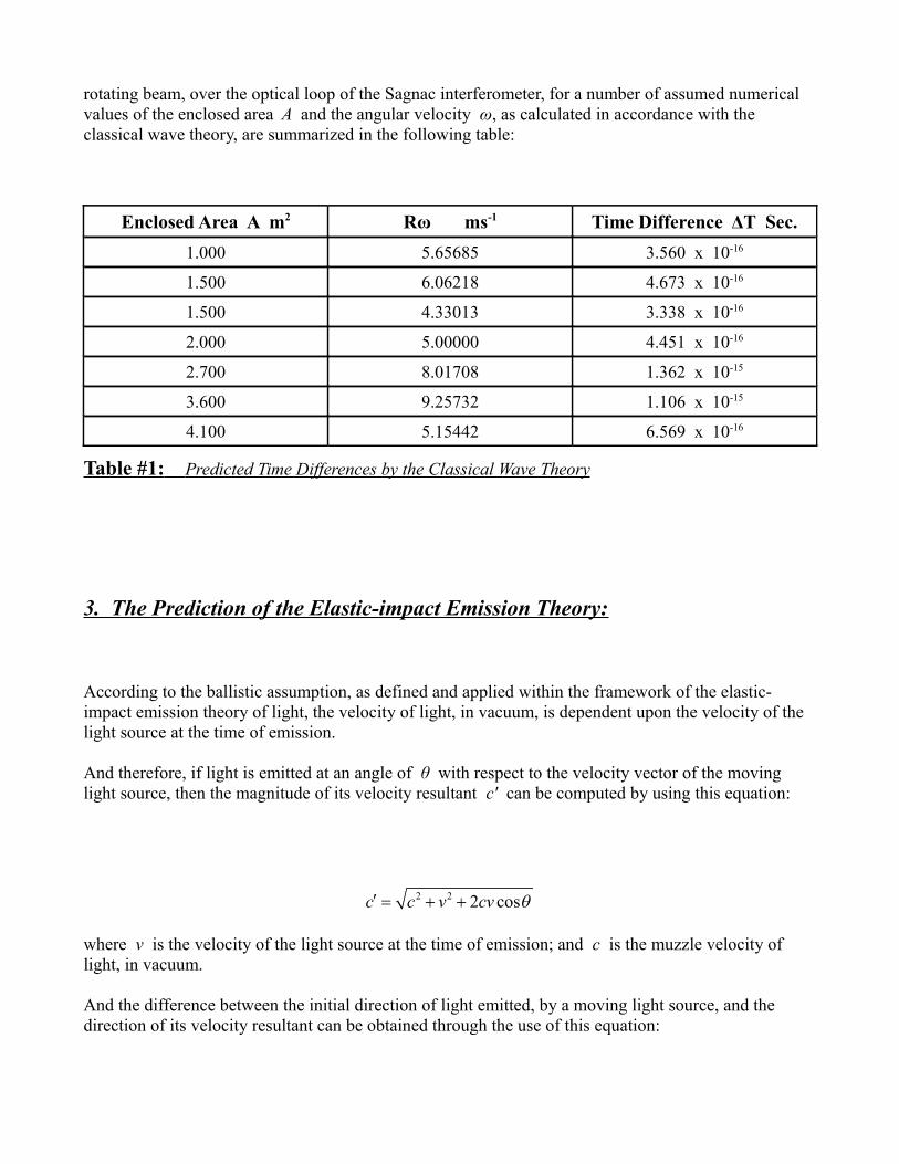
rotating beam, over the optical loop of the Sagnac interferometer, for a number of assumed numerical values of the enclosed area A and the angular velocity ω, as calculated in accordance with the classical wave theory, are summarized in the following table:
Enclosed Area A m2 Rω ms-1 Time Difference ΔT Sec.
1.000 5.65685 3.560 x 10⁻¹⁶
1.500 6.06218 4.673 x 10⁻¹⁶
1.500 4.33013 3.338 x 10⁻¹⁶
2.000 5.00000 4.451 x 10⁻¹⁶
2.700 8.01708 1.362 x 10⁻¹⁵
3.600 9.25732 1.106 x 10⁻¹⁵
4.100 5.15442 6.569 x 10⁻¹⁶
Table #1: Predicted Time Differences by the Classical Wave Theory
3. The Prediction of the Elastic-impact Emission Theory:
According to the ballistic assumption, as defined and applied within the framework of the elastic-impact emission theory of light, the velocity of light, in vacuum, is dependent upon the velocity of the light source at the time of emission.
And therefore, if light is emitted at an angle of θ with respect to the velocity vector of the moving light source, then the magnitude of its velocity resultant c' can be computed by using this equation:
where v is the velocity of the light source at the time of emission; and c is the muzzle velocity of light, in vacuum.
And the difference between the initial direction of light emitted, by a moving light source, and the direction of its velocity resultant can be obtained through the use of this equation:
2 2 2 cosc c v cv q¢ = + +

where Δθ is the difference between the initial direction and the final direction of emitted light from a moving light source.
The change in the direction of emitted light, due to the motion of the light source, plays a central role inthe calculations of the Sagnac effect, in accordance with the ballistic assumption of velocity of light, in vacuum, dependent upon the velocity of the light source at the time of emission.
In particular, because of the change in the direction of emitted light, from a moving light source, the optical path of the co-rotating beam and the optical path of the counter-rotating beam are no longer equal to each other in length.
As a result, any ballistic calculations, in which it's assumed, explicitly or implicitly, that the above two optical paths coincide with each other and have the same length as that of the optical path for light traveling at a constant velocity of c, lead, necessarily, to invalid and erroneous numerical results.
In other words, the headlight effect — the bending of light rays in the forward direction due to the motion of the light source — is very important; and hence, it should never be neglected or overlooked in any kind of computations, based upon the ballistic assumption of velocity of light, in vacuum, dependent upon the velocity of the light source at the time of emission.
As a general rule, in rotating interferometers, if the path length traveled by light, from a stationary lightsource, at a velocity of c, is d, then the path length traveled by light, from a moving light source, at a velocity resultant of c', must change, in accordance with this general formula:
for all values of θ within these two specified ranges:
where d' is the path length of light emitted by a moving light source; θ is the initial direction of light with respect to the velocity vector of the moving light source; and Δθ is the difference between the initial direction and the final direction of emitted light from the same moving light source as calculated
( )sin
sind d
qq q
æ ö¢ = ç ÷ç ÷+ Dè ø
0 180
360 180
o o
o o
q
q
< <
> >
( )2 2
sinsin sin
1 2 cos
v v
c c v c v c
qq qq
é ùê úD = =
¢ ê ú+ +ë û

by using this equation:
where v is the velocity of the moving source.
Let ω stand for the angular velocity of the rotating Sagnac disc; and consequently, at any point locatedat a distance equal to the radius R from the center of rotation:
where v is the tangential velocity at the periphery of the rotating disc.
And let c' denote the velocity resultant of light emitted by a moving source.
Since, in the aforementioned Sagnac interferometer, the initial direction of emitted light makes a 45o angle with the velocity vector of the emitting light source, the magnitude of its velocity resultant c' is given by the following equation:
where v is the tangential velocity of the light source.
The initial beam, from the moving light source S, is split by the beam splitter P into two beams: The co-rotating beam and the counter-rotating beam.
The co-rotating beam is transmitted by the beam splitter P with the same velocity resultant c' and at an angle of 45o towards the mirror M1 to traverse the optical path P'M'1M'2M'3P' and to combine with the counter-rotating beam at the detector D.
While, the counter-rotating beam is reflected by the beam splitter P at a 135o angle and velocity
v Rw=
( )2 2 2 cos 45oc c v cv¢ = + +
2
2
sinarcsin sin arcsin
1 2 cos
v v
c c v vc c
qq q
q
æ öé ùç ÷ê úæ ö ç ÷ê úD = =ç ÷ ç ÷¢ ê úè ø
+ +ç ÷ê úç ÷ë ûè ø

resultant of c" towards the mirror M3 to travel over the optical path P"M"3M"2M"1P" and to combine with the co-rotating beam at the detector D.
I. The Travel Time of the Co-rotating Beam:
The co-rotating beam is transmitted by the beam splitter P at a 45o angle with respect to the vector of its tangential velocity and with a velocity resultant of c':
towards the mirror M1; and reflected by the mirror M1 at the same angle with the same velocity resultant towards the mirror M2; and by the mirror M2 towards the mirror M3; and by the mirror M3 towards the beam splitter P; and finally, transmitted, at the same velocity resultant c', by the beam splitter P towards the detector D to be combined, in the end, with the counter-rotating beam.
Accordingly, the total flight time of the co-rotating beam, over the square P'M'1M'2M'3D', can be obtained by using the following equation:
where Tcor is the total travel time of the co-rotating beam; and L' is obtained from this equation:
in which L is defined by this relation:
( )( )
4 *cos 45 4
*cos 45
ocor
cor o
L T v LT
c c v
é ù¢ + ¢ë û= =¢ ¢ -
( )( )sin 45
sin 45
o
oL L
q
æ ö¢ ç ÷=
ç ÷+ Dè ø
2L R=
( )2 2 2 cos 45oc c v cv¢ = + +
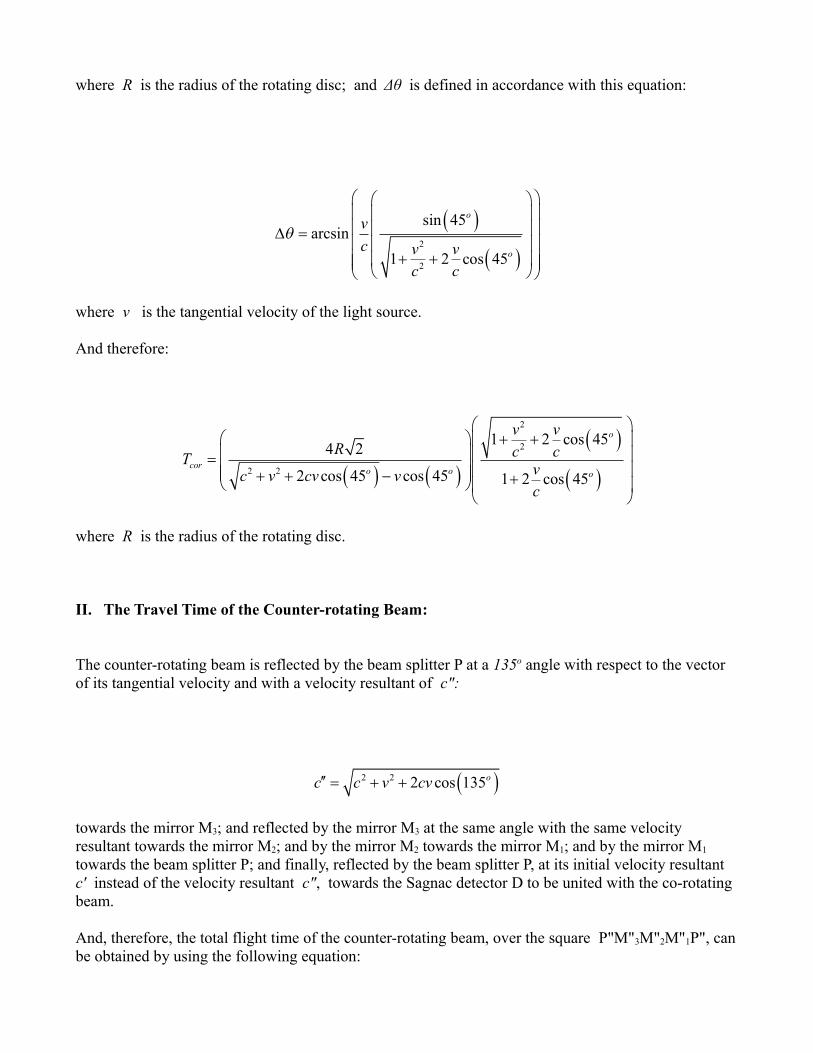
where R is the radius of the rotating disc; and Δθ is defined in accordance with this equation:
where v is the tangential velocity of the light source.
And therefore:
where R is the radius of the rotating disc.
II. The Travel Time of the Counter-rotating Beam:
The counter-rotating beam is reflected by the beam splitter P at a 135o angle with respect to the vector of its tangential velocity and with a velocity resultant of c":
towards the mirror M3; and reflected by the mirror M3 at the same angle with the same velocity resultant towards the mirror M2; and by the mirror M2 towards the mirror M1; and by the mirror M1 towards the beam splitter P; and finally, reflected by the beam splitter P, at its initial velocity resultant c' instead of the velocity resultant c", towards the Sagnac detector D to be united with the co-rotating beam.
And, therefore, the total flight time of the counter-rotating beam, over the square P"M"3M"2M"1P", canbe obtained by using the following equation:
( )
( )2
2
sin 45arcsin
1 2 cos 45
o
o
v
c v vc c
q
æ öæ öç ÷ç ÷ç ÷ç ÷D =ç ÷ç ÷
+ +ç ÷ç ÷ç ÷è øè ø
( )2 2 2 cos 135oc c v cv¢¢ = + +
( ) ( )( )
( )
2
2
2 2
1 2 cos 454 2
2 cos 45 cos 45 1 2 cos 45
o
coro o o
v vR c cT
vc v cv vc
æ öæ ö + +ç ÷ç ÷ç ÷= ç ÷ç ÷ç ÷+ + - +è øç ÷
è ø

where Tcount is the total travel time of the counter-rotating beam; and L" is obtained from this equation:
in which L is defined by this relation:
where R is the radius of the rotating disc; and Δθ' is defined in accordance with this equation:
where v is the tangential velocity of the light source; and:
2L R=
( )( )
4 *cos 135 4
*cos 135
ocount
count o
L T v LT
c c v
é ù¢¢ + ¢¢ë û= =¢¢ ¢¢ -
( )( )sin 135
sin 135
o
oL L
q
æ ö¢¢ ç ÷=
ç ÷¢+ Dè ø
( )
( )2
2
sin 135arcsin
1 2 cos 135
o
o
v
c v vc c
q
æ öæ öç ÷ç ÷ç ÷ç ÷¢D =ç ÷ç ÷
+ +ç ÷ç ÷ç ÷è øè ø
( ) ( )cos 135 cos 45o o= -

And correspondingly:
where R is the radius of the rotating disc.
III. The Predicted Difference in Travel Time:
It follows, therefore, that, on the assumption of velocity of light dependent upon the velocity of the light source at the time of emission, the predicted time difference between the arrival of the counter-rotating beam and the arrival of the co-rotating beam at the Sagnac detector D, can be computed through the use of this equation:
where ΔT is the predicted time difference; and v:
where R is the radius of the rotating disc.
Since, in the 1913 Sagnac experiment, the enclosed area by the light path, A is:
v Rw=
( ) ( )( )
( )
2
2
2 2
1 2 cos 454 2
2 cos 45 cos 45 1 2 cos 45
o
counto o o
v vR c cT
vc v cv vc
æ öæ ö + -ç ÷ç ÷ç ÷= ç ÷ç ÷ç ÷+ - + -è øç ÷
è ø
( ) ( )
( ) ( )
( ) ( )
( ) ( )
2 2
2 2
2 2
2 2
1 2 cos 45 1 2 cos 45 1 2 cos 45 1 2 cos 454 2
1 2 cos 45 cos 45 1 2 cos 45 cos 45
o o o o
count cor
o o o o
v v v v v vR c c c c c c
T T Tc v v v v v v
c c c c c c
é ùæ ö æ öæ ö æ ö+ - - + + +ê úç ÷ ç ÷ç ÷ ç ÷é ù è ø è øê úç ÷ ç ÷D = - = -ê ú ê úç ÷ ç ÷ë û ê úç ÷ ç ÷+ - + + + -ç ÷ ç ÷ê úè ø è øë û

and the angular velocity of the rotating disc, ω is:
the elastic-impact emission theory predicts, in this case, the following numerical value for the time difference between the travel time of the counter-rotating beam and the travel time of co-rotating beam:
The time differences, for a number of assumed values for the enclosed area A and the angular velocity ω, as calculated in accordance with the elastic-impact emission theory, are given in the following table:
Enclosed Area A m2 Rω ms-1 Time Difference ΔT Sec.
1.000 5.65685 3.560 x 10⁻¹⁶
1.500 6.06218 4.673 x 10⁻¹⁶
1.500 4.33013 3.338 x 10⁻¹⁶
2.000 5.00000 4.451 x 10⁻¹⁶
2.700 8.01708 1.362 x 10⁻¹⁵
3.600 9.25732 1.106 x 10⁻¹⁵
4.100 5.15442 6.569 x 10⁻¹⁶
Table #2: Predicted Time Differences by the Elastic-impact Emission Theory
IV. A Brief Evaluation of the Computed Sagnac Effect:
2086 mA =
2 Hzw =
-163.062 10 secondsTD = ´

The following points should be made clear with regard to the aforementioned theoretical predictions and the quantitative treatment of the Sagnac effect:
• As shown in Table #1 & Table #2, for typical tangential velocity values of the rotating Sagnac disc, in laboratory settings, the time-difference equation of the classical wave theory of light and the time-difference equation of the elastic-impact emission theory of light give very close and similar numerical results with regard to the predicted differences between the travel time of the counter-rotating beam and the travel time of the co-rotating beam. For instance, in the case of the 1913 Sagnac experiment, the computed results, on the basis of these two theories, differ from each other by no more than 10-34 of a second.
• However, for hypothetically higher velocity values of the rotating Sagnac interferometer, which by the way would most certainly get the Sagnac mirrors out of their proper alignment, the calculated numerical results, in accordance with the assumption of constant speed of light and the assumption of ballistic speed of light, in vacuum, are substantially different from each other,as demonstrated in Table #3 below:
Area A m2 Rω ms-1 Δtw sec Δtb sec Δtb - Δtw Δtb ∕ Δtw
1.000 0.1 x c 1.896 x 10⁻⁹ 1.930 x 10⁻⁹ 3.389 x 10⁻¹¹ 01.018
2.500 0.3 x c 9.372 x 10⁻⁹ 1.118 x 10⁻⁸ 1.820 x 10⁻⁹ 01.193
3.000 0.5 x c 1.868 x 10⁻⁸ 3.520 x 10⁻⁸ 1.653 x 10⁻⁸ 01.885
4.400 0.7 x c 3.770 x 10⁻⁸ 5.315 x 10⁻⁷ 4.948 x 10⁻⁷ 14.483
Table #3: Comparison of Predicted Time Differences for Larger Values of v
In the above table, A is the area of the optical loop; Rω is the tangential velocity of the light source; Δtw is the time difference calculated according to the classical wave theory; and Δtb is the time difference computed in accordance with theelastic-impact emission theory.
And that is because, even though the values of the predicted time difference Δtw by the classical wave theory continue to increase significantly, with increasing velocity values, by a factor of:
( )12
22
1 cos 45ov
c
-æ ö-ç ÷
è ø

the values of the time difference Δtb by the elastic-impact emission are increasing at a much higher rate with increasing velocity values, due to the increasing difference between the resultant velocity c' of the co-rotating beam:
and the resultant velocity c" of the counter-rotating beam:
where v is the tangential velocity.
• On the assumption of constant speed of light, the co-rotating beam and the counter-rotating beam traverse the same optical square. However, on the assumption of ballistic speed of light, the co-rotating beam traverses a smaller optical square; while the counter-rotating beam traverses a larger optical square than the optical square for a stationary Sagnac interferometer:
• According to the classical wave theory, the counter-rotating beam is the fastest and the co-rotating beam is the slowest. By contrast, on the basis of the elastic-impact emission theory, thecounter-rotating beam is the slowest and the co-rotating beam is the fastest.
• The calculated prediction of the new-source emission theory, with regard to the Sagnac effect, isthe same as the calculated prediction of the classical wave theory, in the presence of a refractivemedium; and the same as the calculated prediction of the elastic-impact emission theory, if the Sagnac experiment is carried out in vacuum. While, by comparison, the computed prediction ofthe Larmor-Lorentz theory, concerning the Sagnac effect, remains always the same as the computed prediction of the classical wave theory.
4. Concluding Remarks:
( )2 2 2 cos 45oc c v cv¢ = + +
( )2 2 2 cos 135oc c v cv¢¢ = + +

Regarding the aforementioned Sagnac experiment, how exactly does the ballistic beaming of the elastic-impact emission theory make the optical loop of the co-rotating beam shorter and the optical loop of the counter-rotating beam longer than those of the non-ballistic beams of the classical wave theory?
From the standpoint of geometrical optics, it's quite easy to visualize the effect of ballistic beaming on the optical loops of the Sagnac interferometer: Just make the case of parallel mirrors the standard reference; and use the given values of tilting angles of the interferometer's mirrors, with respect to the velocity vector of light source, to plot, geometrically, the trajectories of light and to estimate by how much the travel times, in the case in question, deviate from the equal travel times, in the parallel case.
As shown in Figure #5 below:
If the reflecting surface of a plain mirror is parallel to the velocity vector of the light source, then the travel time of the ballistic beam, from the light source S to Point B on the surface of the mirror, and the travel time of the non-ballistic beam, from the light source S to Point A on the surface of the same mirror, are always equal, in accordance with the following relation:
Figure #5: Equal Light Travel Times inthe Case of Parallel Mirrors
A B
CC'
S
V
Δθ
ND
D'
D DT
c c
¢= =
¢

where T is the light travel time; D is the distance from the light source S to Point A; D' is the distance from the light source S to Point B; c is the velocity of light emitted by a stationary light source; and c' is the velocity resultant of light emitted by a moving light source.
And so, as long as the parallel reflecting surface of the mirror does not coincide precisely with the velocity vector of the moving source, the travel time of a light beam traveling at the velocity c, and the travel time of a beam traveling at the velocity resultant c', are always equal, regardless of the numerical values of D, v, & c'.
However, if the reflecting surface of the mirror is tilted, from its parallel position with respect to the velocity vector of the moving light source, the two travel times, under investigation, will become, necessarily, unequal and different from each other by a certain amount of time, depending on the beam towards which the mirror is tilted, and on the angle at which the mirror is tilted.
In the Sagnac interferometer, under discussion, as depicted in Figure #6 below:
The reflecting surface of the mirror M1 is tilted towards the ballistic co-rotating beam at a 90o angle with respect to the velocity vector of the light source. And as a result, the light path of the ballistic co-rotating beam is shortened, on its way in, by the 90o tilting of the reflecting surface, and shortened, on its way out, by the changing values of the angles of incidence and reflection from their initial value of 45o to their new value of (45o – Δθ), because the ballistic beam is shifted, due to the headlight effect, towards the near-end part of the rotating mirror.
That is on one hand.
On the other hand, the reflecting surface of the mirror M3 is titled towards the non-ballistic counter-
Figure #6: Unequal Light Travel Times in the Case of Tilted Mirrors
C"
CC
C'
S
V
Δθ'
Δθ
NM3
M1

rotating beam with a 90o angle with respect to the velocity vector of the light source. And consequently, the light path of the ballistic counter-rotating beam is lengthened, on its way in, by the 90o tilting of the reflecting surface, and lengthened, on its way out, by the changing values of the angles of incidence and reflection from the value of 135o to the value of (135o + Δθ'), because the ballistic beam is shifted, due to the headlight effect, towards the far-end part of the rotating mirror..
As pointed out earlier, in this discussion, the phenomenon of ballistic beaming, effectively, renders the experimental evidence, in all of the investigated cases of the Sagnac effect, inconclusive, with regard toresolving the issue of whether or not light inherits the velocity of its source.
Nonetheless, there are several aspects of the Sagnac interferometer, which suggest, at first glance, that it might potentially, under some circumstances, provide the crucial evidence needed in this regard.
And, definitely, the most attractive among those promising aspects of the Sagnac interferometer to investigate is the rotation of the mirror lines.
Does the rotation of the Sagnac interferometer with an angular velocity of w cause the mirror lines to rotate with the same angular velocity relative to the incident beams as well?
According to the classical wave theory, for example, during the travel time of the co-rotating beam from the beam splitter P to the mirror M1, the Sagnac interferometer, rotates by an angular amount equal to the angle Δϕ:
where R is the radius of the rotating disc; and v is the tangential velocity of M1.
And hence, does the normal line to the surface of the mirror M1 rotate as well by the same angle Δϕ with respect to the co-rotating beam?
The short answer to this question is, of course, yes: The mirror line of M1 does rotate by an angle of Δϕ with respect to the angle of incidence of the co-rotating beam [Ref. #1].
And therefore, if the mirror lines do, indeed, rotate by the above angle of Δϕ relative to the incident beams, then the angles of incidence and reflection must change by the same amount as well, which is, for certain, just the required amount for counteracting the effect of relative velocities of light and wiping out the amount of Sagnac effect, predicted by the classical wave theory, based on the difference between the relative velocity of the co-rotating beam and the relative velocity of the counter-rotating beam, with respect to the Sagnac detector.
Luckily for the classical wave theory, however, upon further inspection, it becomes clear that the rotating mirror lines just can't do it.
( )02 180
cos 45o
R
c vf w
p
æ öæ öç ÷D = ç ÷ç ÷- è øè ø

That is because, in the reference frame of the moving mirror, although the rotating mirror line is shifted, by an amount of Δϕ, towards the incident beam, the incident beam itself, along with the opticalimage of the light source, is shifted, by the same amount of Δϕ, away from the rotating mirror line; and hence, the angle of incidence, for the co-rotating beam remains unchanged and equal to 45o .
And the same is true, in the case of the counter-rotating beam.
And subsequently, the classical wave theory has not been, decisively, ruled out by the rotating mirror lines, in the Sagnac interferometer.
What would have happened to the predicted amount of Sagnac effect, by the elastic-impact emission theory, if there was no shifting of the incident beam, in the reference frame of the moving mirror, away from the rotating mirror line?
If there was no shifting of the incident beams, in the reference frames of the moving mirrors, then the predicted amount of Sagnac effect, on the basis of the ballistic assumption, would be doubled, because the effect of rotating mirror lines, in that case, would increase and magnify by a factor of 2 the headlight effect.
And finally, what would have happened to the predicted amount of the Sagnac effect, by Einstein's theory of special relativity, if there was no shifting of the incident beam, in the reference frame of the moving mirror, away from the rotating mirror line?
If there was no shifting of the incident beam, in the reference frame of the moving mirror, away from the rotating mirror line, the special theory of relativity would have, most certainly, solved one of its twomajor problems with the Sagnac effect, and predicted exactly the observed amount of the fringe shift inthe Sagnac experiment:
• In spite of implementing mathematically the classical relative speed of light in most of its equations, the theory of special relativity has no other option beside declaring verbally that the relative speed of light does not exist; otherwise, this theory would be inconsistent with the null result of the Michelson-Morley experiment, in which the calculated effect of the classical relative speed of light is absent. However, the Sagnac experiment demonstrates, beyond the reasonable doubt, that the co-rotating beam and the counter-rotating beam do, indeed, have twodifferent relative speeds with respect to the moving Sagnac detector.
• But the most serious problem, by far, with the treatment of the Sagnac effect, within the theoretical framework of Einstein's special relativity, is presented by its so-called 'relativistic beaming'. On the basis of this theory, if, in the reference frame of the observer, the light source is moving with a velocity v, and at an angle of θs, during the time of emission, then the initial direction of emitted light must shift to the angle θo, in the forward direction relative to the velocity vector of the moving light source, in accordance with this Einstein's formula:

where c is the speed of light in vacuum.
And as a result, the rays of light, from the moving light source, which reach the observer, are tilted towards the direction of the light source's motion [Ref. #9 & #10]. But, if the co-rotatingbeam and the counter-rotating beam, in the Sagnac experiment, are bent in the forward directionof the velocity vector of the light source, then the total path of the former will become shorter, and the total path of the latter will become longer. And that poses a serious problem to any theory built around the assumption of velocity of light independent of the velocity of the light source. And that is because it counteracts the effect of relative velocities of light and reduces the predicted value of the Sagnac effect to nil – nothing more and nothing less. In other words, Einstein's special relativity, when its relativistic headlight effect is taken into consideration, predicts no fringe shift at all in the Sagnac experiment. And that renders it clearly inconsistent with the observed result of the Sagnac experiment. Nonetheless, can the relativistic light aberration, caused by the tangential velocity of the mirror, counteract and balance out the relativistic headlight effect, caused by the tangential velocity of the light source,in the Sagnac experiment? Unfortunately for the theory of special relativity, a resolution of thissort is neither physically nor mathematically viable. Because its headlight effect produces real bending in the directions of the emitted beams; while, by contrast, its light aberration produces only apparent bending in the directions of the same incident beams. However, although it seems very improbable, it might not be entirely impossible to employ, somehow, the so-called 'length contraction & time dilation', as defined within the framework of Einstein's theory of special relativity, to nullify the adverse effect of its relativistic beaming and to restore the predicted classical value of the Sagnac effect, in accordance with the assumption of velocity of light independent of the velocity of the light source at the time of emission.
And it follows, therefore, that, unless a satisfactory solution to the aforementioned problem is found, the computed prediction of Einstein's theory of special relativity, due mainly to its own relativistic beaming and its own mathematical formula for calculating the headlight effect, will continue to produce a value of zero for the Sagnac effect; and hence, this particular physical theory will have to remain at odds and fundamentally inconsistent with the observed result of the Sagnac experiment.
And now once again, concerning the Sagnac interferometer, under discussion, it might appear potentially promising that if the reflecting surfaces of the two mirrors, M1 & M3, are made parallel to the velocity vector of the light source, then the ballistic velocity of light and the relative velocity of light, in this particular arrangement, will balance each other out; and as a result, the elastic-impact emission theory, unlike the classical wave theory, will predict a zero value for the Sagnac effect.
coscos
1 cos
s
o
s
vc
vc
q
-=
-

However, when the above arrangement is examined closely, it becomes obvious that if the reflecting surfaces of the two mirrors, M1 & M3, are made parallel to the velocity vector of the light source, then the two mirrors, in question, will become active and alter the velocity of incident light, by just the right amount, to produce the same amount of the Sagnac effect, predicted in this special case, by the classicalwave theory.
Another possible arrangement of the Sagnac interferometer, for testing the two theories, under discussion, is to remove the light source and the detector from the rotating Sagnac disc and to place the two together at rest relative to the laboratory. Since it appears, in this case, that the classical wave theory, unlike the elastic-impact emission theory, would predict no fringe shift at all.
Nevertheless, upon close examination of this new arrangement, it becomes obvious that the following Ives' formula for computing the Doppler effect, in the case of multiple reflections from moving mirrors:
in which f ' is the observed frequency; and v is the velocity of the mirror [Ref. #12]; will give, in this particular case, just the right amounts of blue and red Doppler shifts, to produce the same amount of the Sagnac effect predicted, in this new arrangement, by the elastic-impact emission theory.
One more possible arrangement of the Sagnac interferometer, for testing the two physical theories, in question, is to replace the three mirrors with fiber optics. Since it looks like, in this case, that the elastic-impact emission theory, unlike the classical wave theory, would predict no fringe shift whatsoever.
Upon closer examination, however, it becomes evident that the ballistic headlight effect, in this case, will increase the number of reflections for the counter-rotating beam; and at the same time, it will decrease the number of reflections for the co-rotating beam, by just the right amount to make the path of the former, inside the fiber optics, longer, and the path of the latter shorter, and to produce an amountof the Sagnac effect equal to the amount of the Sagnac effect calculated on the basis of the classical wave theory.
It seems very unlikely, therefore, that the rotating Sagnac interferometer can be re-arranged in any practical way to experimentally rule out, in a decisive manner, either the classical wave theory or the elastic-impact emission theory.
But it is not jut the rotating Sagnac interferometer; but also circular motion itself, in general, is highly unlikely to be utilized in any conceivable way to rule in or rule out either the independence of the velocity of light of the velocity of its light source, or the dependence of the velocity of light upon the velocity of its light source at the time of emission.
c vf f
c v
-æ ö¢ = ç ÷+è ø

Let's consider, for example, the case of a laser beam sent from Earth and reflected by the Moon overhead. The computed travel time of the laser beam, on the basis of these two diametrically opposed assumptions, is exactly the same; as it can be inferred, immediately, from the given geometry in Figure#5 below:
A. In the case of the classical wave theory:
The laser beam is sent from Point E, on Earth, reflected back by Point M, on the Moon directly overhead, and received at a point slightly behind Point E', due to rotation of the earth. And accordingly,its total travel time T is given by the following equation:
Figure #7: Lunar Laser Ranging & the Two Assumptions About the Speed of Light
MM
EE'EE'
(B)(A)
C'
C'C
C
d'd

where d is the distance from Earth to the Moon.
B. In the case of the elastic-impact emission theory:
The laser beam is sent from Point E, reflected back by M, and received at Point E'. And therefore, its total travel time T is obtained by using this equation:
where the combined speed, c', in both directions, is calculated in accordance with this equation:
where v is the rotational speed of the earth.
And therefore, even though the laser beam, according to the elastic-impact emission theory, is travelingat a combined speed higher than c, its total travel time is equal to the total travel time of a laser beam traveling at c, because the ballistic headlight effect makes its path in both directions greater than 2d.
It's, justifiably, reasonable, therefore, to conclude that interferometers, in circular motion, generally, arebasically neutral and highly unlikely to provide any strong experimental evidence for or against the proposition of velocity of light independent of the velocity of the light source, or for or against the proposition of velocity of light dependent upon the velocity of the light source. And subsequently, in all likelihood, only interferometers, in uniform linear motion, as in the case of the Michelson-Morley experiment, can distinguish, decisively, between the calculated predictions of the classical wave theory
2 2c c v¢ = +
( )22 12
2 2
22 2d vTd dT
c cc v
+¢= = =
¢ +
2dT
c=

of light and the calculated predictions of the elastic-impact emission theory of light.
REFERENCES:
1. Geometric Optics: "Rotation of Plane-Mirror"
2. Kelly, A. G., "The Sagnac Effect and Uniform Motion"
3. Wolfram MathWorld:
"Circular Segment"
4. Sagnac Interferometer: "Theory & Background"
5. Mathpages.com:
a.) "The Sagnac Effect" b.) "Sagnac and Fizeau" c.) "Ballistic Sagnac"
6. The Sagnac Effect: "A Classical Explanation"
7. Université Paris-Diderot- France: "Paul Langevin and the Sagnac effect (1921)"
8. Georges Sagnac: a.) "The Luminiferous Ether is Detected" b.) "On the Proof of the Reality of the Luminous Ether"

9. WIKIPEDIA (wikipedia.org): "Relativistic aberration"
10. Albert Einstein: "ON THE ELECTRODYNAMICS OF MOVING BODIES"
11. ResearchGate: "Sagnac Effect and Ritz Ballistic Hypothesis (Review)"
12. IVES, E. H., (1940): "The Doppler Effect from Moving Mirrors"
Related Papers:
A. Ballistic Precession: The Anomalous Advance of Planetary Perihelia
B. Doppler Effect on Light Reflected from Revolving Mirrors: A Brief Review of Majorana's 1918 Experiment
C. Mass and Energy:A Brief Analysis of the Mass-Energy Relation
D. Ballistic Doppler Beaming: A Brief Investigation of the Headlight Effect and Aberration of Light
E. The Essence of Time: A Dialogue on its Nature and Various Aspects