Embed Size (px)
Citation preview
Vol-3 Issue-6 2017 IJARIIE-ISSN(O)-2395-4396
7172 www.ijariie.com 1582
A STUDY ON SOIL-STRUCTURE
INTERACTION OF FREE-STANDING
PILE GROUP FOUNDATION USING
FINITE ELEMENT ANALYSIS S.Harish
1, Ch.Damodar Naidu
2
1P.G. student, Civil Engineering Department,Gokul group of institutions,AP, India
2Asst Professor, Civil Engineering Department, Gokul group of institutions,AP , India
ABSTRACT
In recent years, Pile Foundation which is a composite structure consisting pile and raft has been proved to
be an appropriate alternative instead of conventional Raft/ Mat foundations. Raft foundation covers the entire area
of the structure, transmitting the entire structural load and reduces differential settlements, whereas piles are
relatively long & slender members that transmit foundation loads through soil strata of low bearing capacity to
deeper soil ( By skin friction piles) or Rock strata (End bearing piles) where having a high bearing capacity.
Here, analysis of free-standing pile group foundation has been carried out by using finite element software
ANSYS. For understanding the behavior of pile group foundation parametric studies has been carried out in sand
medium by constant pile diameter, different spacing of pile and different pile length with different loading
combinations.
Project object is to simulate free-standing pile group foundation in sandy soil using Finite Element Analysis to
evaluate the deflection & deformations developed under structural load conditions and compare the results.
The results of these studies have led to an improved understanding of the soil-structure interaction problem and
providing greater confidence for its use in further engineering practice.
Keywords: Pile Foundation Raft/ Mat foundations, ANSYS, soil-structure
1. 1. INTRODUCTION
Pile group foundation consists of free-standing piles (1x2) and thin element of raft which is mounted on top of
piles and placed above 500mm from natural ground level. Raft will be used to prevent subsidence.
The Concept of free-standing pile group foundation is important to understand prior to the analysis. When raft
foundations were used the raft-soil interaction is presented similarly, the free-standing piles and their interaction
with the adjacent soil has been discussed, i.e. pile-soil interaction and also the pile-pile interaction when piles are
placed in a group are also discussed. In this dissertation focus is on free-standing pile group foundation in sandy soil.
The presentation of free-standing piles are therefore embedded and confined to cohesion less soil. Thus, end bearing
piles in sand soil has been envisaged in this thesis.
A few years ago, full 3D numerical analyses of deep foundations were reserved to researchers or to expert
analysts in large engineering firms. Pile group foundation is challenging design problems, which they are 3D by
nature and that soil-structure interaction and to the behavior of deep foundations are noted.
This thesis gives an overview on free-standing pile group in ANSYS foundation modeling. Further, analysis has
been done on finite element modeling of different Pile length, different pile spacing also development of linear &
non linear analysis.
Vol-3 Issue-6 2017 IJARIIE-ISSN(O)-2395-4396
7172 www.ijariie.com 1583
In this study two different modeling approaches for analysis and compared with two different loading conditions
such as moment applied and force along with moment applied for analysis of free-standing pile group foundation
with different spacing & different length.
3D finite element models (FEM) are carried out by using programs developed by ANSYS Work bench Release
14.5 for analysis. The plane strain models are similar but differ in the way of modeling the interaction between the
piles and the soil. The first plane strain model is used and the model produce good results in course sand of the pile-
soil interaction. In this study, two alternative models and four different loading conditions are introduced.
In a two dimensional analysis has been done past studies and found simplifications in analysis and thereby
inaccuracies were noted. A 2D model compared to a 3D model will vary depending on the characteristics of the
problem. Hence, 3D FEM for free-standing pile group is considered in this study. However, it could still be
convenient to use this method since it is faster, widely used in India and the ANSYS software is less expensive.
Subsequently, a imaginary free-standing pile group foundation is analyzed in ANSYS 3D to illustrate the
different modeling approaches.
Finally, a parametric study of “FREE-STANDING PILE GROUP FOUNDATION USING FINITE ELEMENT
ANALYSIS” for two different models and with two different loading condition such as Moment and Force +
Moment are performed.
2. Application of ANSYS
ANSYS is also used to analyze Three Dimensional Finite Element Modeling (FEM) for pile foundation
structures. Three dimensional plane strain non-linear analysis under vertical load is carried out using finite element
modeling in ANSYS software to determine settlement of foundation.
Here, pile and raft are treated as linear, soil-raft and soil-pile interface as non-linear and Drucker-Prager
constitute model is used for soil. Here, pile and raft were modeled as linear isotropic and the properties considered
for analysis are Young‟s modulus (E), Poisson‟s ratio (µ) and density for pile and raft.
Soil is modeled as an elasto plastic and in addition to linear material properties, properties like material cohesion
strength (c) and friction angle (φ) is given. For pile, raft and soil, PLANE 82 was used as an element type and the
element behavior is specified as plane strain. The interface behavior is non linear. Contact elements CONTA172
(for soil) and TARGET169 (for pile) at soil-pile interface are considered.
2.1 Boundary Conditions :
Nodes constituting bottom of the soil zone is fixed against both vertical and horizontal directions whereas
the zone away from pile raft, i.e., the vertical surface of soil at the boundary is restricted against horizontal
movements. The horizontal boundary (H) was placed at 5 times the PILE-RAFT cluster diameter (5D) and the
vertical boundary (V) is placed at 2.5 times the PILE Length or RAFT cluster diameter (3D). For validation of
ANSYS, immediate settlement in medium sand are noted for two different models and the same is compared with
the results obtained from ANSYS. FEM Analysis are perform of Linear & Nonlinear-Static Structural Analysis, Soil-Structure Interaction
Analysis, Simulation of Deflection angle & Deformation , Simulation of Stress developed in the Pile, Simulation of
Elastic strain developed in the Pile, Simulation of Plastic strain developed in the Pile and CAD model / drawing
generation
2.2 Modeling:
Diameter of pile is 1.0 m (d) and thin raft size is 6.0 m x 3.0 m x 0.75m for both Models
Model-1: Pile Length(l) is 10m (l/d=10)
spacing of pile (s) is 3m (i.e s/d=3 for 10m length pile)
Case-I : Loading condition : Moment applied
Case-II : Loading condition : Force + Moment applied
Model-2: Pile Length(l) is 20m (l/d=20)
Spacing of pile (s) is 4m (i.e s/d=4 for 20m length pile)
Case-III : Loading condition : Moment applied
Case-IV : Loading condition : Force + Moment applied
Vol-3 Issue-6 2017 IJARIIE-ISSN(O)-2395-4396
7172 www.ijariie.com 1584
Further, input details of basic geometry of pile, theory reference for Pile Foundations in Sand, Material
Specification, Density of the material, Young's Modulus, Poisson‟s ratio and Moment & Force to be applied for
analysis.
2.3 Results of the analysis may have the following parameters:
Deformation on Z axis (Vertical) of individual pile (Upward/downward)
Total deformation of both vertical & horizontal movements
Max Equivalent stress
Max Elastic strain
Max Plastic strain
Deflection/Rotation angle
Distance of point of deflection
2.4 Geometry pile:
The geometry of the pile is defined vertically be specifying two work planes, between which, the
pileshould be drawn. The pile are then defined horizontally by choosing a cross section. There are five different
cross section types available; massive circular pile, circular tube pile, massive square pile, square tube pile and user-
defined shape pile. The tube pile (i.e. hollow pile) are composed of wall elements and the massive pile are composed
of volume elements.
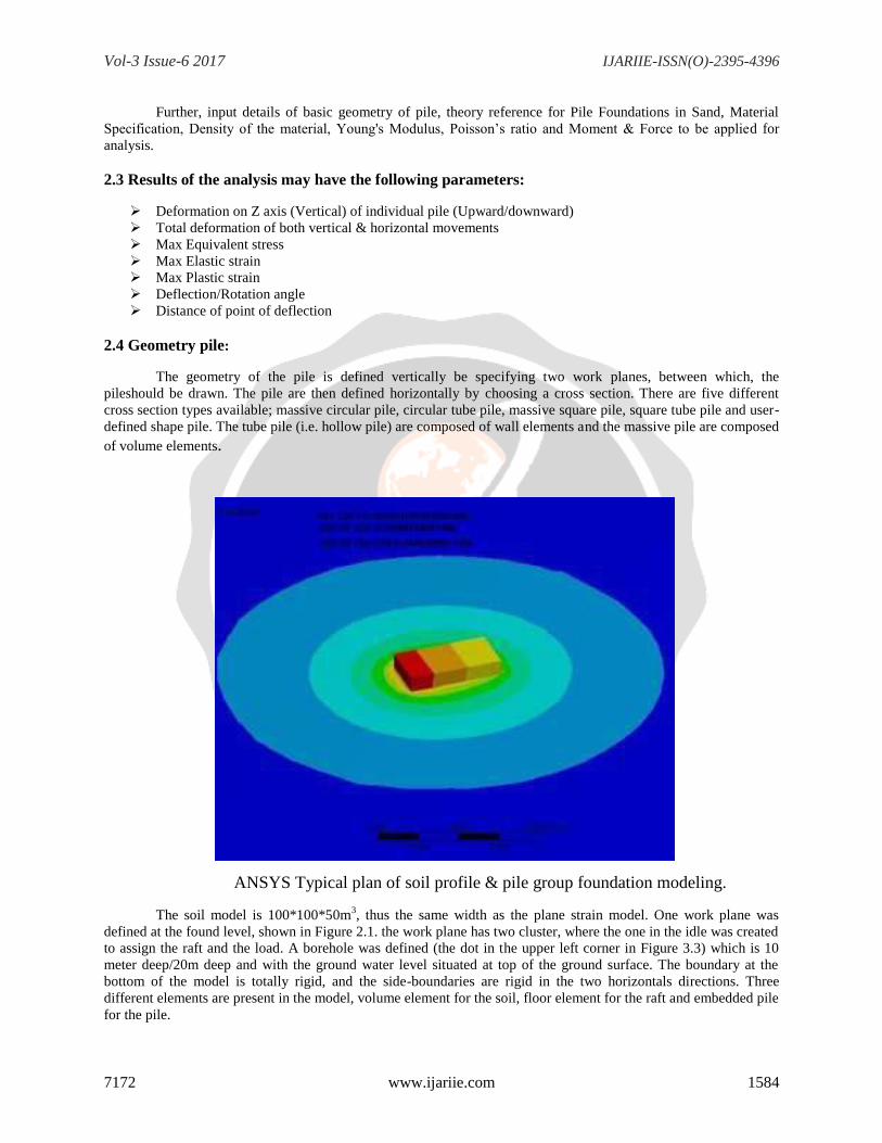
ANSYS Typical plan of soil profile & pile group foundation modeling.
The soil model is 100*100*50m3, thus the same width as the plane strain model. One work plane was
defined at the found level, shown in Figure 2.1. the work plane has two cluster, where the one in the idle was created
to assign the raft and the load. A borehole was defined (the dot in the upper left corner in Figure 3.3) which is 10
meter deep/20m deep and with the ground water level situated at top of the ground surface. The boundary at the
bottom of the model is totally rigid, and the side-boundaries are rigid in the two horizontals directions. Three
different elements are present in the model, volume element for the soil, floor element for the raft and embedded pile
for the pile.
Vol-3 Issue-6 2017 IJARIIE-ISSN(O)-2395-4396
7172 www.ijariie.com 1585
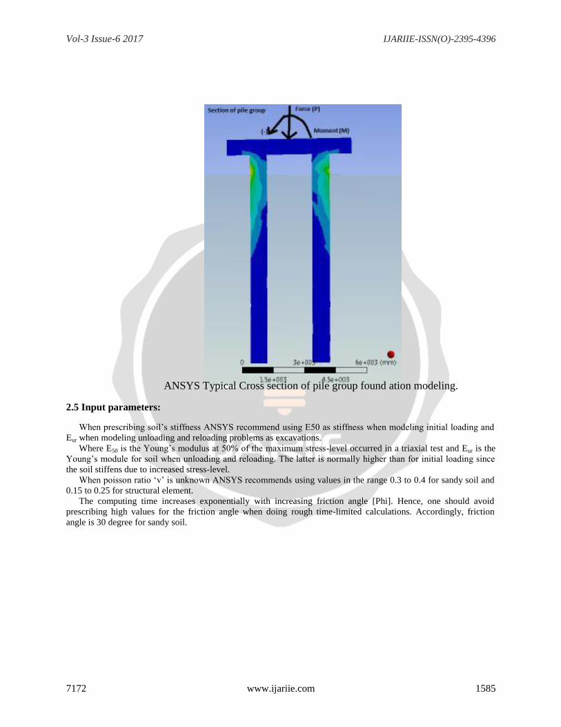
ANSYS Typical Cross section of pile group found ation modeling.
2.5 Input parameters:
When prescribing soil‟s stiffness ANSYS recommend using E50 as stiffness when modeling initial loading and
Eur when modeling unloading and reloading problems as excavations.
Where E50 is the Young‟s modulus at 50% of the maximum stress-level occurred in a triaxial test and Eur is the
Young‟s module for soil when unloading and reloading. The latter is normally higher than for initial loading since
the soil stiffens due to increased stress-level.
When poisson ratio „v‟ is unknown ANSYS recommends using values in the range 0.3 to 0.4 for sandy soil and
0.15 to 0.25 for structural element.
The computing time increases exponentially with increasing friction angle [Phi]. Hence, one should avoid
prescribing high values for the friction angle when doing rough time-limited calculations. Accordingly, friction
angle is 30 degree for sandy soil.
Vol-3 Issue-6 2017 IJARIIE-ISSN(O)-2395-4396
7172 www.ijariie.com 1586
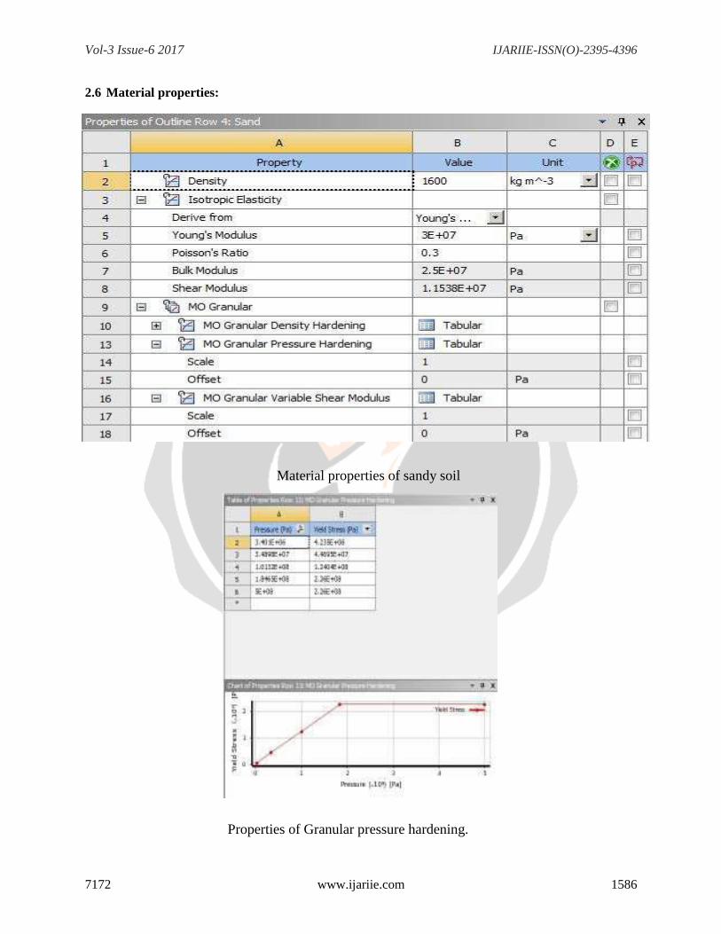
2.6 Material properties:
Material properties of sandy soil
Properties of Granular pressure hardening.
Vol-3 Issue-6 2017 IJARIIE-ISSN(O)-2395-4396
7172 www.ijariie.com 1587
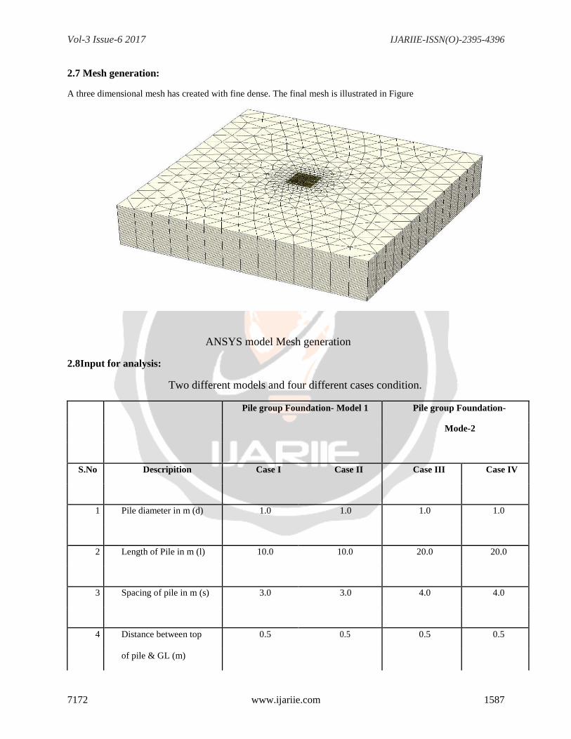
2.7 Mesh generation:
A three dimensional mesh has created with fine dense. The final mesh is illustrated in Figure
ANSYS model Mesh generation
2.8Input for analysis:
Two different models and four different cases condition.
Pile group Foundation- Model 1 Pile group Foundation-
Mode-2
S.No Descripition Case I Case II Case III Case IV
1 Pile diameter in m (d) 1.0 1.0 1.0 1.0
2 Length of Pile in m (l) 10.0 10.0 20.0 20.0
3 Spacing of pile in m (s) 3.0 3.0 4.0 4.0
4 Distance between top 0.5 0.5 0.5 0.5
of pile & GL (m)
Vol-3 Issue-6 2017 IJARIIE-ISSN(O)-2395-4396
7172 www.ijariie.com 1588
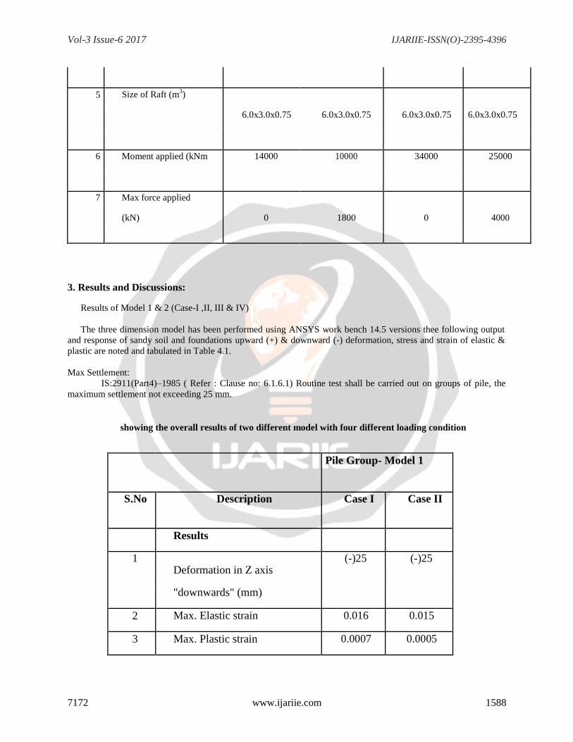
5 Size of Raft (m3)
6.0x3.0x0.75 6.0x3.0x0.75 6.0x3.0x0.75 6.0x3.0x0.75
6 Moment applied (kNm 14000 10000 34000 25000
7 Max force applied
(kN) 0 1800 0 4000
3. Results and Discussions:
Results of Model 1 & 2 (Case-I ,II, III & IV)
The three dimension model has been performed using ANSYS work bench 14.5 versions thee following output
and response of sandy soil and foundations upward (+) & downward (-) deformation, stress and strain of elastic &
plastic are noted and tabulated in Table 4.1.
Max Settlement:
IS:2911(Part4)–1985 ( Refer : Clause no: 6.1.6.1) Routine test shall be carried out on groups of pile, the
maximum settlement not exceeding 25 mm.
showing the overall results of two different model with four different loading condition
Pile Group- Model 1
S.No Description Case I Case II
Results
1 Deformation in Z axis
(-)25 (-)25
"downwards" (mm)
2 Max. Elastic strain 0.016 0.015
3 Max. Plastic strain 0.0007 0.0005
Vol-3 Issue-6 2017 IJARIIE-ISSN(O)-2395-4396
7172 www.ijariie.com 1589
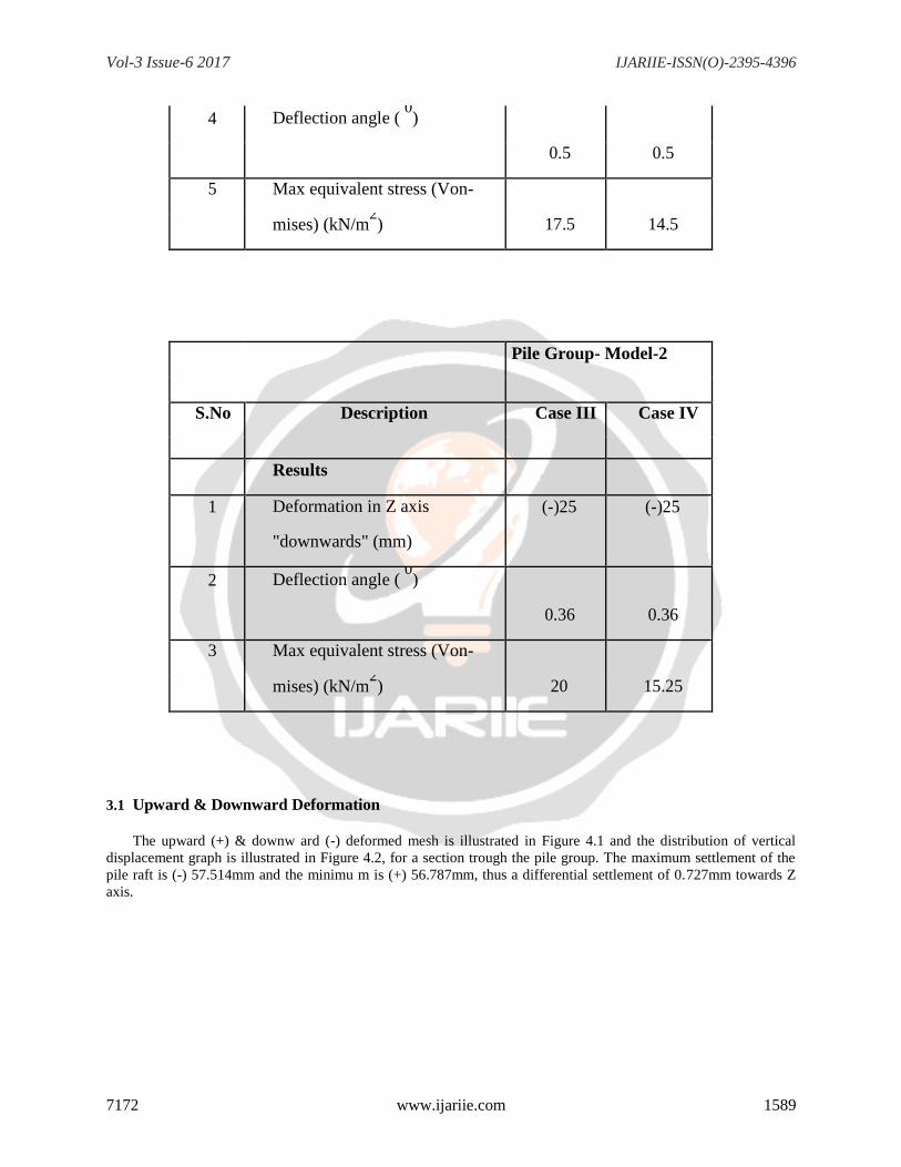
4 Deflection angle ( 0)
0.5 0.5
5 Max equivalent stress (Von-
mises) (kN/m2) 17.5 14.5
Pile Group- Model-2
S.No Description Case III Case IV
Results
1 Deformation in Z axis (-)25 (-)25
"downwards" (mm)
2 Deflection angle ( 0)
0.36 0.36
3 Max equivalent stress (Von-
mises) (kN/m2) 20 15.25
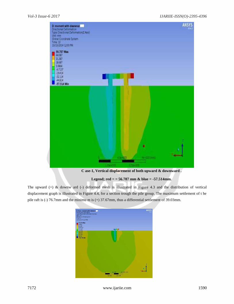
3.1 Upward & Downward Deformation
The upward (+) & downw ard (-) deformed mesh is illustrated in Figure 4.1 and the distribution of vertical
displacement graph is illustrated in Figure 4.2, for a section trough the pile group. The maximum settlement of the
pile raft is (-) 57.514mm and the minimu m is (+) 56.787mm, thus a differential settlement of 0.727mm towards Z
axis.
Vol-3 Issue-6 2017 IJARIIE-ISSN(O)-2395-4396
7172 www.ijariie.com 1590
C ase-1, Vertical displacement of both upward & downward .
Legend; red = = 56.787 mm & blue = -57.514mm.
The upward (+) & downw ard (-) deformed mesh is illustrated in Figure 4.3 and the distribution of vertical
displacement graph is illustrated in Figure 4.4, for a section trough the pile group. The maximum settlement of t he
pile raft is (-) 76.7mm and the minimu m is (+) 37.67mm, thus a differential settlement of 39.03mm.
Vol-3 Issue-6 2017 IJARIIE-ISSN(O)-2395-4396
7172 www.ijariie.com 1591
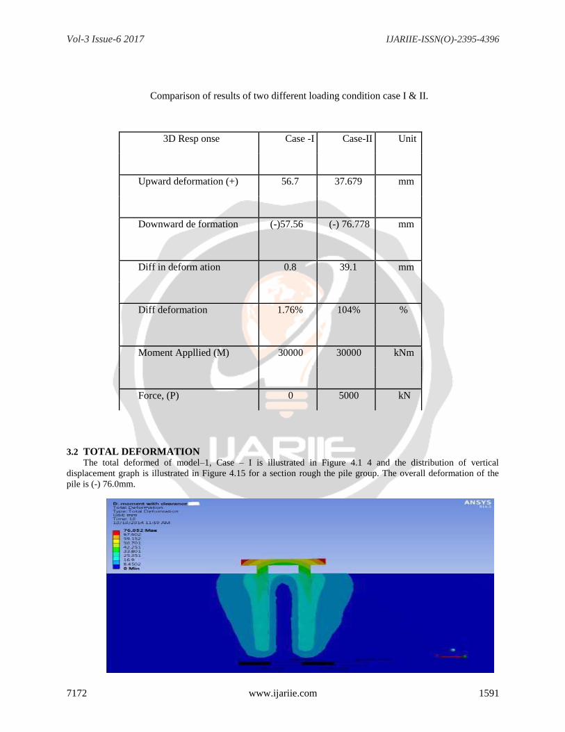
Comparison of results of two different loading condition case I & II.
3D Resp onse Case -I Case-II Unit
Upward deformation (+) 56.7 37.679 mm
Downward de formation (-)57.56 (-) 76.778 mm
Diff in deform ation 0.8 39.1 mm
Diff deformation 1.76% 104% %
Moment Appllied (M) 30000 30000 kNm
Force, (P) 0 5000 kN
3.2 TOTAL DEFORMATION
The total deformed of model–1, Case – I is illustrated in Figure 4.1 4 and the distribution of vertical
displacement graph is illustrated in Figure 4.15 for a section rough the pile group. The overall deformation of the
pile is (-) 76.0mm.
Vol-3 Issue-6 2017 IJARIIE-ISSN(O)-2395-4396
7172 www.ijariie.com 1592
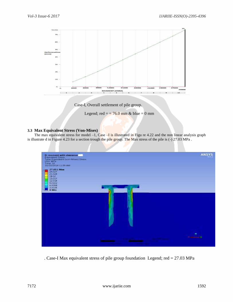
Case-I, Overall settlement of pile group.
Legend; red = = 76.0 mm & blue = 0 mm
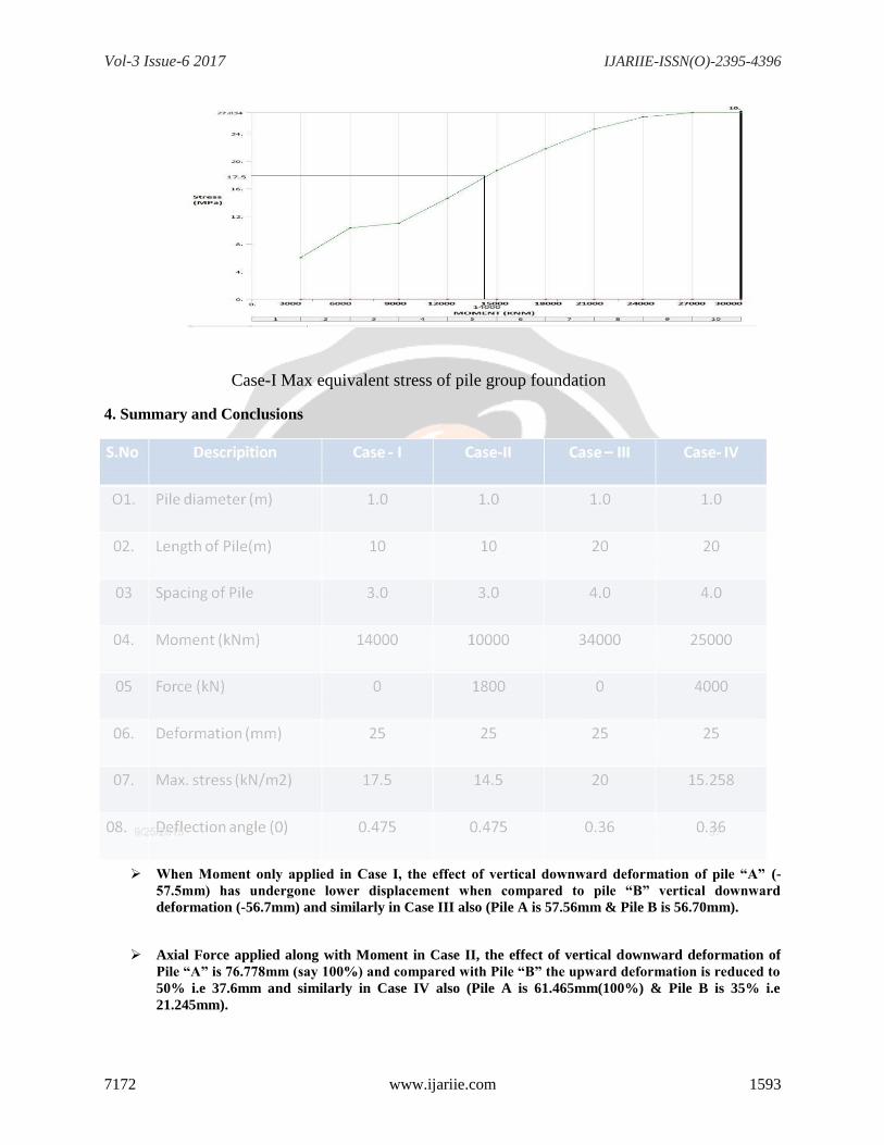
3.3 Max Equivalent Stress (Von-Mises) The max equivalent stress for model –1, Case –I is illustrated in Figu re 4.22 and the non linear analysis graph
is illustrate d in Figure 4.23 for a section trough the pile group. The Max stress of the pile is (-) 27.03 MPa .
. Case-I Max equivalent stress of pile group foundation Legend; red = 27.03 MPa
Vol-3 Issue-6 2017 IJARIIE-ISSN(O)-2395-4396
7172 www.ijariie.com 1593
Case-I Max equivalent stress of pile group foundation
4. Summary and Conclusions
When Moment only applied in Case I, the effect of vertical downward deformation of pile “A” (-
57.5mm) has undergone lower displacement when compared to pile “B” vertical downward
deformation (-56.7mm) and similarly in Case III also (Pile A is 57.56mm & Pile B is 56.70mm).
Axial Force applied along with Moment in Case II, the effect of vertical downward deformation of
Pile “A” is 76.778mm (say 100%) and compared with Pile “B” the upward deformation is reduced to
50% i.e 37.6mm and similarly in Case IV also (Pile A is 61.465mm(100%) & Pile B is 35% i.e
21.245mm).
Vol-3 Issue-6 2017 IJARIIE-ISSN(O)-2395-4396
7172 www.ijariie.com 1594
The overall deformation in Case I & II are 114.20 & 114.378 mm respectively which is having
L=10.0m & S =3.0m but Case III & IV deformation are 114.26mm & 82.71mm respectively which is
having L=20.0m & S=4.0m. Therefore, length increase deformation is reduces in pile group
foundation
References:
1. U.K.Nath, P.J.Hazarika, V.Giri, A.M.Tesfaye (2011) “Study of lateral Resistance of Pile
cap using Finite Element Analysis” International journal of emerging trends in
Engineering and Development, Issue1, Vol -1, pp. 15- 31.
2. W.D.Guo & E.H.Ghee (2010) “Model test on Free-standing passive pile groups in Sand”
Janvary 2010, Conference paper on Physical Modelling in Geotechnics –Springman,
Laue & Seward (eds), Taylor & Francis Group, London, pp. 873-878.
3. Sanjeev Kumarh and Michael L. Hall
lateral force on piles or piers installed to support a structure through sliding soil mass”
Journal.