Embed Size (px)
Citation preview
_': p_s_ ¸
DEGRADATION OF HUBBLE SPACE TELESCOPE
METALLIZED TEFLON ® FEP THERMAL CONTROL MATERIALS
Patricia A. Hansen, Jacqueline A. Townsend
NASA/Goddard Space Flight Center
Greenbelt, Maryland 20771
Yukio Yoshikawa, J. David Castro
Lockheed Martin Technical Operations
Greenbelt, Maryland 20770
Jack J. Triolo and Wanda C. Peters
Swales Aerospace
Beltsville, Maryland 20705
ABSTRACT
The mechanical and optical properties of the metallized Teflon ® Fluorinated Ethylene
Propylene (FEP) thermal control materials on the Hubble Space Telescope (HST) have
degraded over the seven years the telescope has been in orbit. Astronaut observations and
photographic documentation from the Second Servicing Mission revealed severe cracks of the
multi-layer insulation (MLI) blanket outer layer in many locations around the telescope,
particularly on solar facing surfaces.
Two samples, the outer Teflon ® FEP MLI layer and radiator surfaces, were characterized post-
mission through exhaustive mechanical, thermal, chemical, and optical testing. The observed
damage to the thermal control materials, the sample retrieval and handling, and the significant
changes to the radiator surfaces of HST will be discussed. Each of these issues is addressed
with respect to current and future mission requirements.
KEY WORDS: Hubble Space Telescope, Multi-Layer Insulation, Teflon ® Fluorinated
Ethylene Propylene (FEP)
1. INTRODUCTION
The Hubble Space Telescope (HST) was launched in April 1990 and deployed at an orbital
altitude of 598 km (320 nmi) and 28.5 ° orbit inclination. The Telescope's mission is to spend
https://ntrs.nasa.gov/search.jsp?R=19980237247 2018-05-11T09:14:07+00:00Z

15 yearsprobing the farthest and faintest reachesof the cosmos. Crucial to fulfilling thispromiseis a seriesof on-orbit mannedservicingmissionsto upgradescientific capabilities.TheFirst ServicingMission(SM1) took placein December1993,3.6 yearsafter deployment.The SecondServicingMission(SM2) followed in February1997,6.8 yearsafter deployment.Two subsequentservicingmissionsarealsoscheduledfor late1999andearly2002.
Astronautobservationsandphotographicdocumentationfrom theSM2 revealedseverecracksof the multi-layerinsulation(MLI) blanketouter layerin manylocationsaroundthe telescope,particularlyon solarfacing surfaces.Two sampleswere retrievedduring the SM2, the outerTeflon® FEP MLI layer and radiator surface,and were characterizedpost-missionthroughexhaustivemechanical,thermal,chemical,andoptical testing. This paperdetailsthe observeddamageto thethermalcontrol materials,the sampleretrievalandhandling,andthe significantchangesto the radiator surfacesof HST. Eachof theseissuesis addressedwith respecttocurrentandfuturemissionrequirements.
2. HST DESCRIPTION
As shown in Figure 1, the HST houses the five scientific instruments (Sis) and three Fine
Guidance Sensors in the Aft Shroud (AS). The Support Systems Module (SSM) Bays, located
directly above the AS, house the batteries, tape recorders, and house keeping equipment. The
Forward Shell (FS) and Light Shield (LS) is the structure enclosing the primary and secondary
mirror and stray light rejection baffles. The Aperture Door (AD) is closed only during
servicing periods or safe hold modes to protect the primary and secondary mirrors from direct
sun impingement and contamination.
The HST uses several thermal control materials to passively control temperatures on-orbit.
These materials are of two primary types: radiators and MLI blankets. As shown in Figure 2,
the radiator surfaces are the AS, Att Bulkhead, AD, and SSM Bays and louvers on the SMM
Bays. The radiator surfaces are 5 mil Teflon ® FEP/Ag/Inconel bonded to the vehicle substrate
(aluminum) with acrylic adhesive. All other surfaces are blanketed.
3. HST ON-ORBIT ENVIRONMENT
The HST thermal control system (TCS) is exposed to the low Earth orbit (LEO) environment
which includes solar radiation, particle radiation and atomic oxygen. Solar exposure, including
near ultraviolet radiation, vacuum ultraviolet radiation, and soft x-rays from solar flares, may
cause surface damage in polymeric materials such as Teflon ® FEP. Trapped electron and
proton particle radiation may cause mechanical or chemical property changes in the bulk of the
polymeric material. Atomic oxygen can erode polymeric materials such as Teflon ® FEP
through chemical reactions with gaseous oxide products.

Table1 summarizestheHST environmentalexposuresexperiencedby the HST samples.Thefluencesshown in Table l do not take into accountscatteringof atomic oxygen or solarradiationoff of othersurfaceson thetelescope.
Table1. HST Sample Environmental Fluences
Sample
SM2
MLI
SM2
CVC
Equivalentsun hr
(ESH)
33,638
19,308
X-ray fluence
(Jim 2)
0.5-4A: 16
1-8/1,: 252.4
0.5-4A: 6.1
1-8A: 96.9
Trapped electrons and
proton fluence > 40 keV
(#/cm 2)electrons: 2.14 x 10¹³
protons: 1.83 x 101°
Plasma
fluence
(#/cm 2)
electrons:
4.66 x 10¹⁹
protons:1.63 x 10¹⁹
Atomic
Oxygen
(atoms/cm 2)1.64 x 10²o
4. THERMAL SUBSYSTEM DESCRIPTION
The HST TCS is designed to control temperatures of SSM components and the structure that
interfaces with the Optical Telescope Assembly (OTA) and Sis. The TCS provides thermal
control for all SSM equipment during all mission phases and is passive to the maximum extent
possible. The SSM uses passive thermal control design consisting of insulation, component
arrangement, and mounting configurations augmented with thermostatically controlled heaters.
Louver systems are used for the battery bays.
4.1 MLI Blankets MLI blankets are used on over 80 percent of the external surface area of
HST. These blankets have a FOSR (Flexible Optical Solar Reflector) outer layer (5 mil
aluminized Teflon ® FEP) which is reflective to energy in the solar spectrum to minimize the
effect of solar orientation and day/night cycling on spacecraft temperatures. The MLI blankets
insulate the structure from the external thermal environment, thus conserving heater power and
minimizing temperature extremes and gradients. The baseline MLI design is 15 layers of
embossed Double-aluminized Kapton ® (DAK) with an outer layer of 5 mil FOSR and an inner
layer of I mil single Aluminized Kapton ® (SAK). The surface properties of this outer layer
control the external blanket maximum temperatures to 20°C or less. No spacers are used
between the layers since the embossing pattern reduces layer-to-layer conduction and meets
the Orbiter flammability requirements.
The blankets are closed out on all four sides with a taped cap section and the layers are tied
together throughout the blanket using a pattern of 10 mil acrylic transfer adhesive film. Where
the blankets were cut to fit around stantions, handrails, portable foot restraint sockets, etc., the
blanket was closed out by taping a cap section using 10 mil acrylic transfer adhesive film. In
addition, where the blankets were vented ("X" cuts), the outer layer was reinforced Using
aluminized Kapton ® scrim tape. Velcro ® was stitched to the internal layer, which was

reinforcedwith aluminizedKapton* scrimtape. To indicate fold lines on the SSM Bay doors
blankets, the blankets were stitched through all the blanket layers.
4.2 Radiators The radiator surfaces are perforated 5 mil Silver FOSR bonded with acrylic
adhesive to the (aluminum) substrate. This material was purchased in 4-inch (width) rolls with
the adhesive already applied. The FOSR was applied in sections and a Teflon* wand was used
to minimize air entrapment between the FOSR and the substrate. Damaged FOSR was
replaced as required during the buildup of the telescope. The AD external surface is 5 mil
Aluminized FOSR.
5. SM2 OBSERVATIONS
One of the objectives during the SM2 was to photo document the condition of the telescope
external surfaces. During EVA (extravehicular activity) periods, photography of the telescope
was performed highlighting damaged MLI areas as requested. During Crew sleep periods, the
telescope was systematically photographed.
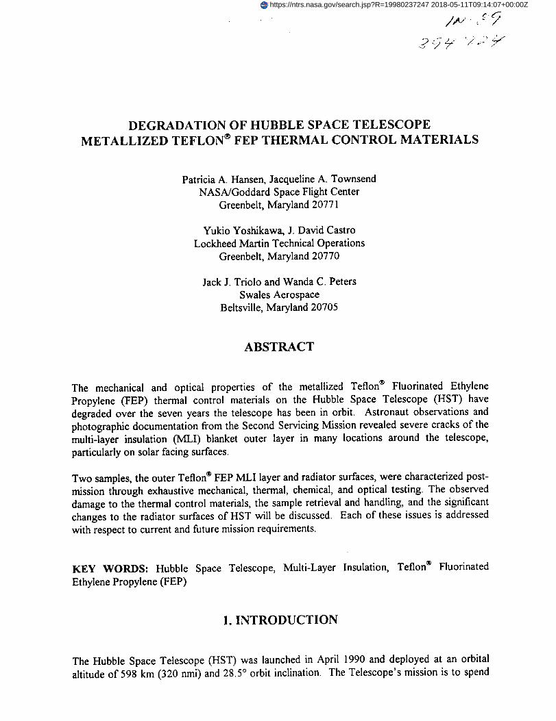
5.1 On-Orbit During the HST SM2, damage of the MLI was observed on the +V3 side
(sun side) with several large cracks in the light shield MLI outer layer (above the stowed High
Gain Antenna). This large crack is shown in Figure 3. Upon further visual observations of the
vehicle, additional cracks were seen on all MLI surfaces. Cracking of the MLI outer layer was
seen all over the telescope, with the most damage seen on the LS, SSM Bay 8, SSM Bay 7,
and SSM Bay 10. The SSM Bay 8 is shown in Figure 4; the MLI is cracked around most of
the bay perimeter, and the MLI appears as though it is partially detached and lifted away from
the telescope.
Prior to patching the corners of the SSM Bay 8 MLI, the astronauts performed two tests: a
Velcro* cycling and Teflon* FEP bend test. The Velcro*, attaching the MLI blanket to the
bay, was cycled to determine its integrity - was it still attached to the telescope substrate and
did the hook still hold the pile securely? The astronauts reported that the Velcro* appeared to
be securely fastened to the vehicle substrate and the hook seemed to hold the pile securely.
The astronauts also bent a piece of the Teflon* FEP over on itself to determine if manipulating
it during the patching process would cause significant damage. The astronauts reported that
the Teflon* FEP did not crack.
Although the damage to the MLI was visually dramatic, there was no measurable thermal
effect due to the cracks and the exposure of the DAK to the telescope environment. However,
during the SM2 mission, a program decision was made to reconfigure flown MLI patches to
patch the worst of these damaged areas.
5.2 Damage Map Post mission analysis of the photographic documentation indicated that
the MLI outer layer was cracked extensively on all MLI surfaces. The cracks were noticeably
larger and more numerous on the sun side (+V3) of the telescope. The cracks in the FEPTeflon on the anti-sun side (-V3) of the telescope tended to start and end at stress

concentrationpoints. Whereas,thecrackson the sunside(+V3) of thetelescopestartat stressconcentrationpointsandeitherendwheretwo cracksmeetor in themiddleof anMLI blanket.
Figure 5 showsa mapof the MLI damage,using SM2 photo documentation(Reference3).
This map depicts the damage and notes where the cracks have opened on the LS and SSM
bays. The location of the features on the map is approximate and shown for illustration
purposes only. The most important item to note is that the damage is seen all over the vehicle
and is noticeably worse on the sun side (+V3).
6. SAMPLE DESCRIPTION
6.1 MLI Sample An MLI sample, shown in Figure 6, was taken from the upper LS crack
prior to patching the area. The LS MLI cracks are shown with patches installed in Figure 7.
The sample was cut fight to left with a change in the initial direction of the cut as the
astronauts realized they were cutting through the sample. The sample is shown flat in Figure
8; the astronaut cuts, on-orbit cracks and handling cracks are identified. The sample was
handled carefully and stored in an EVA trash bag for the duration of the EVA. The trash bag
was transferred to the crew cabin and the sample was placed in a reclosable polyethylene bag
and stowed in a middeck locker for the duration of the mission. The sample was requested as
an early destow item and was turned over to the HST project within 6 hours of the Orbiter
landing.
The sample was transferred to a poylcarbonate container and transported via over night courier
service to the Goddard Space Flight Center (GSFC). Upon arrival at GSFC, a small portion of
the sample was photo documented. The sample was then stored in a laboratory until testing.
6.2 Radiator Sample As part of the installation of the Near Infrared Camera Multi-Object
Spectrometer, a cryogen vent line was routed through the Aft Bulkhead to expel Nitrogen boil
off from the instrument. As a result, the Cryogen Vent Cover (CVC) was removed and
returned to Earth at project request. The outside of the CVC (radiator surface) had been
exposed to the HST ambient environment and provided a good data point for the thermal
degradation of the radiator surfaces. This Att Bulkhead (-V1) surface was exposed to direct
solar incident radiation, however, it was significantly less than the MLI sample from the LS.
The telescope sun angle history has been compiled and is shown in Table 1 as equivalent solar
hours (ESH).
7. DISCUSSION
7.1 MLI Sample The MLI sample was characterized through exhaustive mechanical,
thermal, chemical, and optical testing. The testing revealed several changes to the mechanical,
chemical and thermal properties of the MLI. Details of these tests may be found in References
4-7. The on-orbit cracks are nearly featureless indicating that they occurred very slowly under
low load and in the presence of a damaging environmental factor. This crack mechanism is

similarto stress-corrosioncrackingin metalsandslowcrackgrowth in ceramics.The materialshowssignificantreductionin ultimatestrengthand elongation,indicatingthrough-thicknessembrittlementof the Teflon® FEP. The surfaceof the Teflon® FEP is de-fluorinatedfrominteractionwith theorbital environment.Increasesin the solarabsorptanceof theTeflon®FEPcorrelatewell with the numberof daysspentin space,ratherthanwith equivalentsolarhours.The aluminumbackingis crackedin a "mud tiling" patterndueto the differencein thermalexpansionof the Teflon® FEP and the aluminum and the 40,000 thermal cycles HSTexperienced.It is expectedthat theconditionof theMLI will continueto degrade,andthat itwill befragileby thenextservicingmission.
7.2 Radiator Sample The radiator sample was characterized through exhaustive
mechanical, thermal, chemical, and optical testing. Testing of the CVC sample showed that the
solar absorptance of the bonded silver Teflon ® FEP on the AS of HST has increased. Flight
temperature data plots of the maximum and minimum temperatures over several years show an
increase of the maximum temperatures to indicate a solar absorptance increase whereas the
minimum temperatures remained constant to indicate no emittance change (or no Teflon ® FEP
thickness decrease). As with the MLI, the Teflon ® FEP bonded to the aft shroud is embrittled,
and the silver backing is extensively cracked. The application process used (the angle of
application and rubbing to insure adhesion), has been shown to induce cracking in the metal
layer. The acrylic adhesive can bleed through the cracks and then darken in the presence of
UV and VUV, thus increasing the absorptance of the film. Post mission ground testing has
shown that removing the release strip from the Teflon ® FEP tape caused a significant amount
of cracking of the silver even before application to the substrate.
Additional exposure of the CVC sample to ultraviolet radiation showed that the solar
absorptance did not continue to degrade. However, newly bonded 5 mil Teflon ® FEP, exposed
at the same time to ultraviolet radiation experienced a significant increase in solar absorptance
during the first 2000 hours of exposure. The newly bonded Teflon ® FEP was bonded using
both standard techniques and a "gentle" technique to minimize the cracking of the silver. The
standard technique produced the largest increase in the solar absorptance; however, the
"gentle" technique still produced a significant absorptance increase. This indicated that the
techniques used to bond the Teflon ® FEP to the substrate causes the silver to break in the
application process and thus allows the adhesive to darken under exposure to ultraviolet
radiation. Using a Teflon ® wand to smooth the Teflon ® FEP also caused localized absorptance
increases. The expected degradation of the HST TCS (increase in solar absorptance) is given
in Figure 9 with the CVC sample degradation indicated.
8. FUTURE REQUIREMENTS
To maintain the operational capability during HST's 15-year mission, the TCS must maintain
the HST operational temperatures during all sun pointing attitudes. To continue to meet this
requirement, candidate replacement materials have been selected to repair and/or replace
degraded MLI during subsequent servicing missions. References 8-9, detail the evaluation of
the candidate materials and the current HST metallized 5 mil Teflon ® FEP. Additional testing

of 5 mil aluminized Teflon ® FEP will be on going to predict the expected condition of the
Teflon ® FEP during the future servicing missions.
9. ACKNOWLEDGEMENTS
As with any large test program, many people, behind the scenes, need to be acknowledged for
their contribution: Diane Kolos and Robert Gorman for their excellent photo documentation,
Ted Gregory and Janet Barth for their analyses. In addition, the authors would like to
gratefully acknowledge the contributions of the entire HST MLI Failure Review Board.
10. REFERENCES
1. Hubble Space Telescope Thermal Control System Description and Operating Manual,
LMSC/F420173A, 15 October 1991.
2. HST 2na Servicing Mission Media Reference Guide, February 1997.
3. Hubble Space Telescope SM2 Multi-Layer Insulation (ML1) Damage Assessment, NASA
Document JSC-27943, August 7, 1997.
4. J.A. Dever, K.K. de Groh, J.A. Townsend, L.L. Wang, "Mechanical Properties
Degradation of Teflon ® FEP Returned From the Hubble Space Telescope", NASA/TM-
1998-206618.
5. J.A. Townsend, P.A. Hansen, J.A. Dever, J.J. Triolo, "Analysis of Retrieved Hubble Space
Telescope Thermal Control Materials", Science of Advanced Materials and Process
Engineering Series, 43, 000 (1998).
6. C. He and J.A. Townsend, "Solar absorptance of the Teflon ® FEP Samples Returned from
the HST Servicing Missions", Science of Advanced Materials and Process Engineering
Series, 43,000 (1998).
7. L. Wang and M. Viens, "Fractography of MLI Teflon ® FEP From the HST Second
Servicing Mission", Science of Advanced Materials and Process Engineering Series, 43,
000 (1998).
8. J.A. Dever, J.A. Townsend, J.R. Gaier, A.I. Jalics, "Synchrotron VUV and Soft X-Ray
Radiation Effects on Aluminized Teflon ® FEP", Science of Advanced Materials and
Process Engineering Series, 43,000 (1998).
9. J.A. Townsend, P.A. Hansen, J.A. Dever, J.J. Triolo, "Evaluation and Selection of
Replacement Thermal Control Materials for the Hubble Space Telescope", Science of
Advanced Materials and Process Engineering Series, 43,000 (1998).

\
0006
Figure l: HST Configuration
/- ALUMINIZED FLEXIBLE CP-;ICAL SOL_r_ _FLF:_ _CTOP. _F,O_r(J/ ._'J-:3EG
ML;LTII ,AY'Z,FI
_,-"'_- , - LIGH I" _ _;(]F;_,%',',F._>_, _QUIPhf-'...N_. "" _" _ / r '.L_ . - "
" [ #,LLhMINIZEO $_LVE_IZED I .// \\
¢ -#
11O'='TlC_L 1_1 _.'I!i F-'r'--Jll \\ I/,'3_.C:.K",,... .I........ "'!!1 I I fl \\ /I
GF_:I
KTO_ 1g:_I 6
Figure 2: HST Thermal Control Subsystem Materials Location Map
• . .o
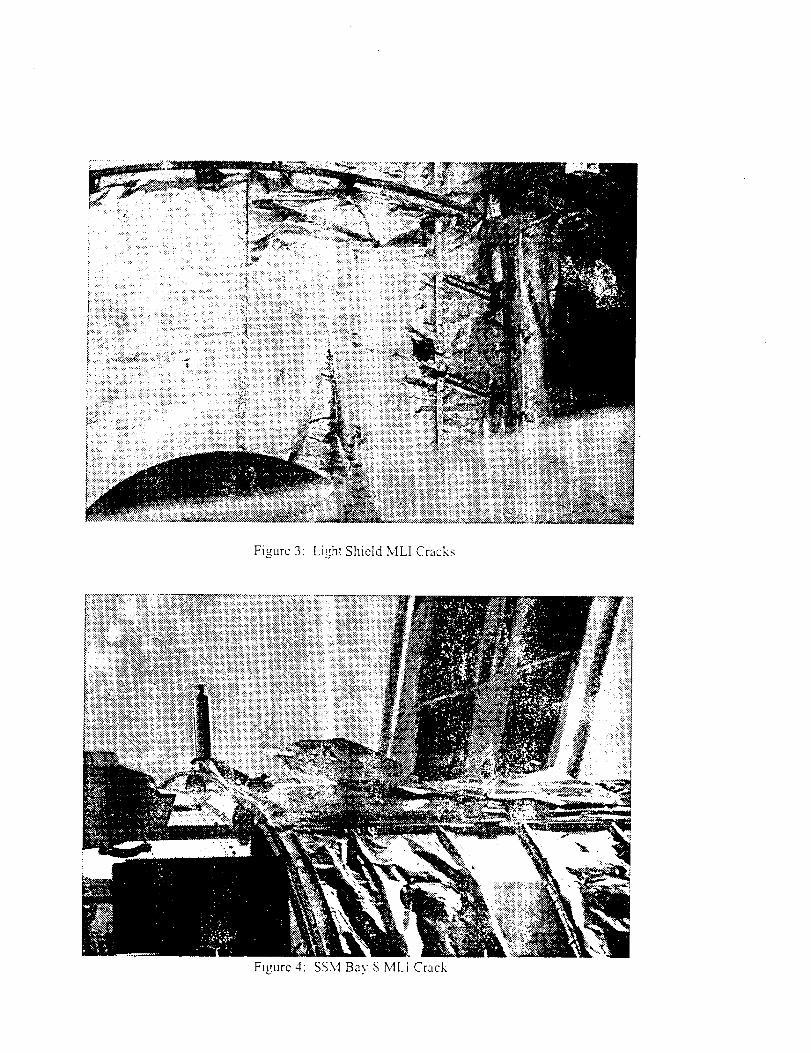
Figure 3: Light Shield MLI Cracks
Figure 4: SSMBavSMLICrack

A
HST MLI Damage(Damage Identified)
3 4 12 5 6 7 8 9 10 11 1 2
A
B B
C C
D D
E E
F F
G
a H
I
3 4 12 5 6 7 8 9 I0 11 1
J
2
Figure 5: HST Thermal Control Subsystem Degradation Map

Figure6: UpperLightShieldMLI Crack(SM2Sample)
Figure7: HSTLightShieldML1CrackswithPatchesInstalled

CrackPropagated Crack Initiation(in space)+ ,....... (in space) Scissors Cut
_"_:_ .... \ \ /(pre-launch)
•' I1"_''ll. _,z:,'gO
"_..... ....'-,._>_!.'X:i ;_ ':_7_}:_"',¢'_" .'N_-:_t_,_ -_: -,," _> _-. "
..... ,: -;_,_<_....,:,,,_,,._,,.,, :/, _ ..... , .-. Crack Pro a ated
_:;_ "':"%_q.,'fft_i_.._ _ _j_ (in space)
Cut
'_-"--Astronaut Cut
Sample
Figure 8:SM2 Teflon FEP
:. :.:
Melahted Teflon Oegfadahon
: °_°t- _:./ ._;......
o,_t-'1//7_.._==:'"_ j -.,,_,.___.o.Io / LSMLI oo,I: -xo.,.
0 1 2 3 4 S 6 7 8 9
T_mo on Otbd, y_s
Mctatizml "l'cl]oi_ degrailaiioll (ill goosyllchr(lliOUS orbil UlIICS_otherwise indicatud}
Relk:rence: "Satelli(e Thermal Conirol l-landbook", b G. Gilmore, Editor,
A_'lt)_,paCC Corpol'iiti(.)ll
Figure 9: HST Solar Absorbtance Measurements versus Predictions

NASA SCIENTIFIC AND £ECHNICAL" DOCUMENT AVAILABILITY AUTHORIZATION (DAA)
To be initiated by the responsible NASA Project Officer, Technical Monitor, or othbr appropriate (CASI Use Only)
NASA official for all presentations, reports, papers, and proceedings that contain scientific [X°r_girml control No.and technical information. Explanations are on the back of this form and are presented In [] Modifiedgreater detail in NHB 2200.2, "NASA Scientific and Technical Information Handbook." Dale
I. D_UMENT/P_Ji_C_DENT_F_CAT_)N_qf_qnabO_ontsmed_p_i1bO_umentstmn_geJh_be ml;leatlKI olmppt UtJe.d_ll_4pnd,cl_tract numper_,., _ 1_,:ueqraoal:]on OT HUDDle :>pace ,eiescope Retai ilzeo leTion I-tv inermai i, ontro RateriAuthor(s):P- Hansen_ J. Townsend, Y. Yoshikawa, D. Castro, J. lriolo, and N. Peterso_,..tingNASAO*gsn=,t_,n:NASA/GSFC, Code 545
Pedormtng Or_nlzation (If dmoront)
Contrect/Grant/tnters0ency/Projecl Number(s)
Document Number(s) Document Date:
,For pmsentstions 04"externally jp.IJ_lisll|id (;|pcuments, im4er Ikopropril.ta i.nfo_on on the mtended .publication=such ,_ name, pls_:_ and Opateofconf^erence, p_747_r_urnal tit..or book title ancl pub|isher: q.troInternatlona/ :>ARI'b :>.ymposlum= Rnanelm= t.p.= b/.11/_t_ -These documents must be routed to NASA Head(luartam. IntarnatJonal Affaim Dwision tar Ikoprovel, (See Sec'tJonVII))
IL AVAILABILITY CATEGORY
Check the appropnate catsgory(iee);
Secunty Cla/sifc.atJon: [] Secret [] Secret RD [] Confioentiel [] Confidential RD EXunctassified
Export Controlled Document - Documents marked in this block must be muted to NASA Headquarters Intarnelmnel Affairs Dnnlgon for approval,
[] ITAR [] EAR
NASA Reelricted DiMribution Document
[] FEDD [] LJmited Dtetdbut|on [] Sl:)e¢_l Conditions-See Section III
Document disclosing in invention
[] Documents marked in this bio¢_ muet be withheld from rt_NUle until six months have elapsed after submission of this form, unless • difloront relelmebets is oetabliehed by the _nata oo_teel. (See Section IX).
Pul_cty Available Document
[XPtJblicly ivailld)io documents must be unolmified and may not be oxport-controlisd or metrCtsd dtethbution documents.
n copyr_med 0{NotcoW,_hted
IlL SPECIAL CONDITIONS
Check one or more of the apglitelNe boxes in each Of (&) and (b) as the bests tar Special rsstnctsd disffibut]on ff the "Spe¢iel Conditions" box under NASARestn¢led Otetrtbutk>n Document in Section it is _. Guid_ines are provided on revenm side of form.
s. This document contains:
[] Fo_0gn go_q)mment informabon [] CommercmJ I:xoducl reel or eValUation results r-i l_lirmmiry information [-1 Informabon sub_ct to specmi contract provision
[] OU_r--Spsc_
b. Check one of the following limita_oml as Ikoproprtata:
r-i U.S. Government agencies and U.S. Government agency contrecto_ only [] NASA contractors and U.S. Government agencms only D U.S. Government a0encms only
[] NASA I_Nlonrml and NASA _ only [] NASA p_qlo_r_l only [] Avellsble only _ al:_rov_ Of isluing Office;
IV. BLANKET RELEASE (OPTIONAL)
All documents _lued under the following _ol_rsc_mnt/woject number
The blanket relearn autt)orizatk_ granted is:Date
[] Ras¢tr_. Ft{tu_ (tocum_l_l n_JF have individual iwdll_llly authodzltidnl.
V. PROJEC_ OF_CEFI/TECHNICAL blONITOR -
Patric_a A. HansenTyped Name of Pro_lct OffK:er/'l'echn¢,al Monitor _/
|
VI. PROGRAM OFFICE REVIEW
H. Richard Freeman
Typed Namo Of Plogram Office Reprseentattvl
VII.
be proteem_d as checked in Sectons II and IlL
INTERNAI3ONAL AFFAIRS DIVISION REVIEW
[] Open, domuUc confm prmmnt_k_n aplxo_Kl.
[] Modlflld - IJmltationl for ell dotumen_ proceslNKI in the STI eystsm under the bl_nl_t
rlMem ehould be (:hanged to conform to blocks as checked in Sect_n II.
545Offal Code Date r
I_ts
/
[] Export _ IIm_ is not _.
[] The Iollow_ng Export tx_liod Ilmltabon (fTAR/EAR) is mm=gned to thle document:
Affairs Div, Fl_Dmeantsthrs TIt_e Date
VIII. EXPIRATION OF REVIEW TIME
Tbe bocun_nt is I_ing mI_ZlNKI in aco_'dlnce w#h I1_1ava_kd_Wty cltlgory lad Iimnatlon oh_k_ k_Sectlo_ ii idn_ no objecbon was m_Ned _ _ _r_O_lk_ w_th_n20 days Of zubmis_don, se zl_m_k|d by NHB 2200.|P., and approval by U_ Intam_1_o_zl Affelm D_sion is not redulnKi.
N_me & TI_ O_ca Co_
NOW: This nm p_ure cannot be used wlm do_ deelgn_ as F_ Co_ed Documents, oongemn_ pr_enUmon= or foreign pu_ica_ion=.
Date --
IX. DOCUMENTS DISCLOSING AN INVE_
& 1'1"_ clocument may be releaucl cmI:)me
b. Tbe ck_oument vm- ixocu_KI on
_ Pit.it or Intel_'u_ P._¢ty _
M aocofdanse veffil SocUonl II anti Ill u i_. NASA CASI
CF427,MAY 92 (REV_