Embed Size (px)
Citation preview

EFC
F P
roce
edin
gs fo
r Con
fere
nce
(not
pub
lishe
d ve
rsio
n) 13th European SOFC & SOE Forum 3 - 6 July 2018, Lucerne/Switzerland
Electrode and Cell Modelling Stack and System Modelling Chapter 06 - Sessions A13, A14 - 338/418
www.EFCF.com/Lib
ISBN 978-3-905592-23-8
A1403 (Candidate: EFCF Special Issue Series, www.EFCF.com/LIB)
Thermo-mechanical reliability of SOFC stacks: impact of component tolerances and operating conditions
Fabio Greco (1), Arata Nakajo (1), Zacharie Wuillemin (2), Jan Van herle (1) (1) GEM Group, Institute of Mechanical Engineering, Faculty of Engineering Sciences
and Technology, EPFL Valais Wallis, Rue de l’industrie 17, CH-1951 Sion, Switzerland (2) SOLIDpower-HTceramix, Avenue des Sports 26,
CH-1400 Yverdon-les Bains, Switzerland Tel.: +41-21-695-8301 [email protected]
Abstract
The reliability of solid oxide fuel cell (SOFC) systems is closing the gap to meet the requirements for market implementation. However, with the recent advances of the technology, the lifetime of SOFC stacks is becoming increasingly limited by mechanical failures, which need to be overcome for lowering costs. Numerical thermo-mechanical investigations are relevant to understand and predict potential failure modes in SOFC stacks, because of the complexity induced by the variety in materials, local conditions and effect of history. Standard finite-element (FE) stack modelling approaches commonly consider idealised components, i.e. computational domains imported from computer-aided design. To further advance the understanding of mechanical failure in the light of cost reductions, statistical variability in the dimensions and geometry of the produced stack components - because of imperfections in the manufacturing processes - must be accounted for. This study is focused on the effects of variability in the flatness of the metallic interconnect (MIC) on the distribution of the contact pressure over the active area. The component initial deformations are included in a 3-D thermo-mechanical model of a series of single repeating units (SRUs). The anisotropic elastic and creep properties of the gas-diffusion layer (GDL) materials are estimated by computational homogenization. This allows the modelling of the GDLs as simplified continuum geometries to reduce the stack simulation runtime. The stack conditioning procedure is simulated to account for the effects of the stack manufacturing on the stress-state before operation. After this initialisation step, the simulation of stack operation consists in importing temperature profiles from thermo-electrochemical simulations into the FE thermo-mechanical model. The simulated operation scenario is long-term polarisation in co-flow configuration, interrupted by thermal cycles. The simulation results show that MIC pre-deformation cause a less uniform distribution of the contact pressure over the active area. Thermal cycling at the beginning of operation appears as the most critical situation (based on inspection of the contact pressure). The situation tends to improve during prolonged polarisation.
EFC
F P
roce
edin
gs fo
r Con
fere
nce
(not
pub
lishe
d ve
rsio
n) 13th European SOFC & SOE Forum 3 - 6 July 2018, Lucerne/Switzerland
Electrode and Cell Modelling Stack and System Modelling Chapter 06 - Sessions A13, A14 - 339/418
www.EFCF.com/Lib
ISBN 978-3-905592-23-8
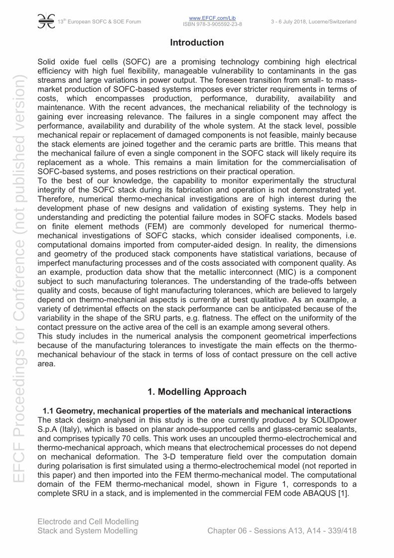
Introduction Solid oxide fuel cells (SOFC) are a promising technology combining high electrical efficiency with high fuel flexibility, manageable vulnerability to contaminants in the gas streams and large variations in power output. The foreseen transition from small- to mass-market production of SOFC-based systems imposes ever stricter requirements in terms of costs, which encompasses production, performance, durability, availability and maintenance. With the recent advances, the mechanical reliability of the technology is gaining ever increasing relevance. The failures in a single component may affect the performance, availability and durability of the whole system. At the stack level, possible mechanical repair or replacement of damaged components is not feasible, mainly because the stack elements are joined together and the ceramic parts are brittle. This means that the mechanical failure of even a single component in the SOFC stack will likely require its replacement as a whole. This remains a main limitation for the commercialisation of SOFC-based systems, and poses restrictions on their practical operation. To the best of our knowledge, the capability to monitor experimentally the structural integrity of the SOFC stack during its fabrication and operation is not demonstrated yet. Therefore, numerical thermo-mechanical investigations are of high interest during the development phase of new designs and validation of existing systems. They help in understanding and predicting the potential failure modes in SOFC stacks. Models based on finite element methods (FEM) are commonly developed for numerical thermo-mechanical investigations of SOFC stacks, which consider idealised components, i.e. computational domains imported from computer-aided design. In reality, the dimensions and geometry of the produced stack components have statistical variations, because of imperfect manufacturing processes and of the costs associated with component quality. As an example, production data show that the metallic interconnect (MIC) is a component subject to such manufacturing tolerances. The understanding of the trade-offs between quality and costs, because of tight manufacturing tolerances, which are believed to largely depend on thermo-mechanical aspects is currently at best qualitative. As an example, a variety of detrimental effects on the stack performance can be anticipated because of the variability in the shape of the SRU parts, e.g. flatness. The effect on the uniformity of the contact pressure on the active area of the cell is an example among several others. This study includes in the numerical analysis the component geometrical imperfections because of the manufacturing tolerances to investigate the main effects on the thermo-mechanical behaviour of the stack in terms of loss of contact pressure on the cell active area.
1. Modelling Approach
1.1 Geometry, mechanical properties of the materials and mechanical interactions The stack design analysed in this study is the one currently produced by SOLIDpower S.p.A (Italy), which is based on planar anode-supported cells and glass-ceramic sealants, and comprises typically 70 cells. This work uses an uncoupled thermo-electrochemical and thermo-mechanical approach, which means that electrochemical processes do not depend on mechanical deformation. The 3-D temperature field over the computation domain during polarisation is first simulated using a thermo-electrochemical model (not reported in this paper) and then imported into the FEM thermo-mechanical model. The computational domain of the FEM thermo-mechanical model, shown in Figure 1, corresponds to a complete SRU in a stack, and is implemented in the commercial FEM code ABAQUS [1].

EFC
F P
roce
edin
gs fo
r Con
fere
nce
(not
pub
lishe
d ve
rsio
n) 13th European SOFC & SOE Forum 3 - 6 July 2018, Lucerne/Switzerland
Electrode and Cell Modelling Stack and System Modelling Chapter 06 - Sessions A13, A14 - 340/418
www.EFCF.com/Lib
ISBN 978-3-905592-23-8
Figure 1: Upper: exploded view of the geometry of the SRU. Lower: schematic view of the
mechanical interactions (shown in dashed lines) between the SRU components. For all SRU materials, temperature-dependent thermo-elastic properties are included in the model. All ceramic components and sealants are assumed to follow a linear elastic behaviour, whereas elasto-plasticity with an isotropic hardening law is used for the metallic parts. In this work, creep (only secondary regime) is implemented in all SRU materials. To reduce the computational requirements and model run-time, the anisotropic elastic and creep properties of the GDLs implemented in the model are estimated by an extension of the computational homogenisation reported in the literature [2]. The contact mechanical interaction comprises both a normal and a tangential behaviour model. In this study, the normal behaviour follows a “softened” non-linear pressure-overclosure relationship. The enforcement of this relationship is approximated by the penalty method, resulting in a contact force that is proportional to the penetration distance, hence allowing a certain inter-penetration of the contacting surfaces and thus a better convergence and an acceptable overclosure as the contact pressure builds up. The pressure-overclosure relationship does not include the separation behaviour of the contact surfaces (except for the interface ∂Ω, see Figure 1), to reduce the computational requirements and the simulation runtime. For the interfaces ∂ΩCL (those of the contact layers, see Figure 1), the penalty stiffness of the pressure-overclosure relationship is reduced such that negligible tensile stresses at the interfaces are simulated in the case clearance is detected. On the contrary, the penalty stiffness of the interfaces ∂ΩSLT (those of the sealants with the MICs and the cell, see Figure 1) is identical to the stiffness of the sealant material. For the tangential contact behaviour, the model uses a frictionless sliding approach until the end of the first heat up, i.e. interfaces with e.g. contact or sealing pastes do not constrain the relative sliding of the parts in contact. Once the simulated temperature reaches the crystallisation temperature of the glass-ceramic sealants, i.e. at the end of the first stack heat-up, a no-sliding condition is enforced for all contact interfaces (except for the interface ∂Ω), which aims at simulating the bonding caused by the sintering of both the contact pastes and the glass-ceramic sealants.

EFC
F P
roce
edin
gs fo
r Con
fere
nce
(not
pub
lishe
d ve
rsio
n) 13th European SOFC & SOE Forum 3 - 6 July 2018, Lucerne/Switzerland
Electrode and Cell Modelling Stack and System Modelling Chapter 06 - Sessions A13, A14 - 341/418
www.EFCF.com/Lib
ISBN 978-3-905592-23-8
1.2 Boundary conditions Two limiting cases were treated to investigate the conditions of SRUs or cluster of SRUs close to the middle of the stack or to the end plates. The first case is that of a stack made of an infinite number of units, without variations in gas flow among the height i.e., approximating a real situation where (i) the analysed SRU is far from the end-plates (ii) the stack is relatively large and (iii) the loading system can accommodate differences in expansion along the flow path. An intuitive approach for simulating such situation consists in enforcing modified periodic boundary conditions (referred hereafter as PBC) [3]. With these boundary conditions, the periodicity of the displacements on the in-plane directions is enforced, whereas the respective nodes on the lower and upper MIC are allowed to rotate around the z-axis, as shown in Figure 2. This relative rotation is constrained to be the same for all nodes on which the PBCs are applied. In the case of SRUs, the temperature difference along the gas flow path causes the outlet air side of the stack to be hotter and thus to expand more than at the inlet.
Figure 2: Representation of the simulated displacement of the upper and lower MICs of one SRU using enforced MIC flatness (FBC, on the top) and modified periodic boundary
conditions (PBC, at the bottom).
The second case is that of SRUs close to the end plates or approximating a real situation closer to that of a short stack. Oppositely to the case of modified PBC, here the upper and lower MICs of the SRU are enforced to remain flat (FBC), whereas their rotation around the z-axis is still allowed, see Figure 2. In this work, reduction of the computational requirements and simulation runtime is achieved because of the assumed symmetry of the stack along the z direction in terms of i) SRU geometry ii) temperature field under polarisation and iii) geometrical imperfections.
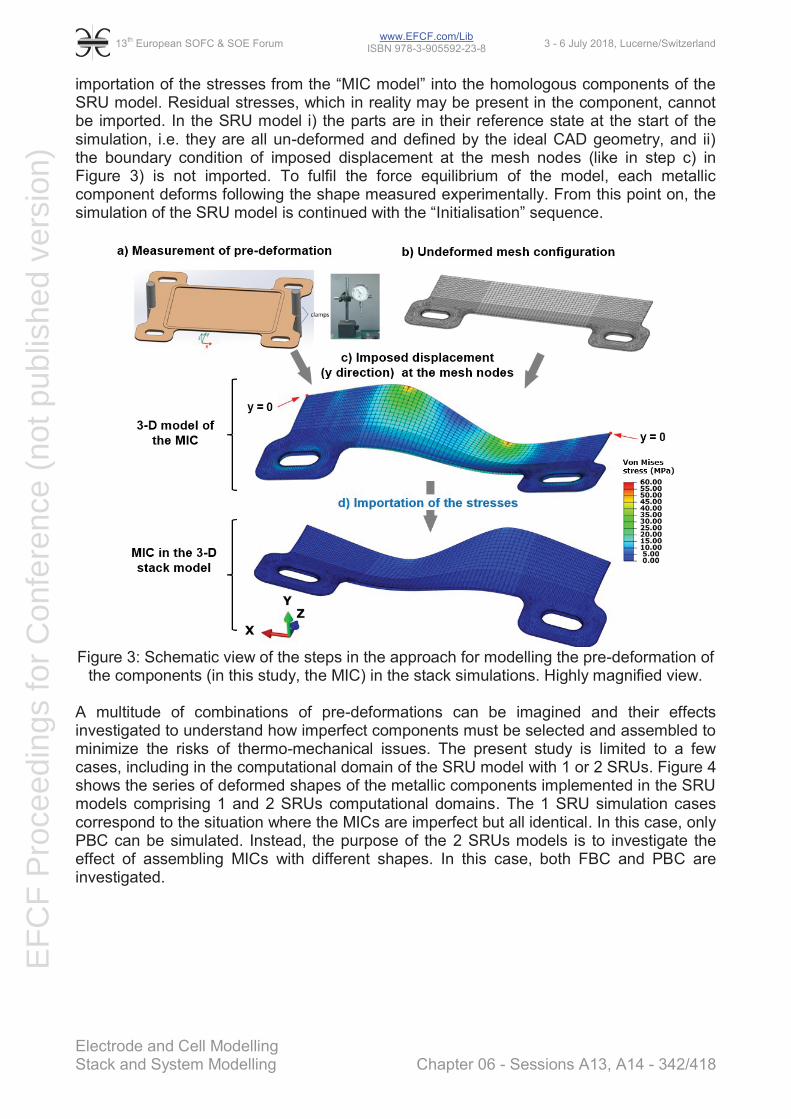
1.3 Implementation of component geometrical imperfections The variations in the shape of the SRU components because of imperfections in their manufacturing or design alternatives are simulated by applying artificial deformations to the component. The developed procedure, illustrated in Figure 3, consists firstly of the measurement of the deflection of the MIC (the component here considered subject to manufacturing tolerances) as a function of the in-plane directions. A separate FEM model (hereafter referred to as “MIC model”) including only the metallic components of the SRU, is then needed to compute artificial stress under imposed deformation for importation in the full SRU model. The displacements along the y-axis (measured in step a)) are applied on each mesh node of the “MIC model” but in the opposite direction and the stresses computed. Because the stress field has the only purpose of generating a deformation, the MIC model assumes linear elastic behaviour without plasticity for all the components, which is one caveat of the approach. The implemented workflow then consists in the
EFC
F P
roce
edin
gs fo
r Con
fere
nce
(not
pub
lishe
d ve
rsio
n) 13th European SOFC & SOE Forum 3 - 6 July 2018, Lucerne/Switzerland
Electrode and Cell Modelling Stack and System Modelling Chapter 06 - Sessions A13, A14 - 342/418
www.EFCF.com/Lib
ISBN 978-3-905592-23-8
importation of the stresses from the “MIC model” into the homologous components of the SRU model. Residual stresses, which in reality may be present in the component, cannot be imported. In the SRU model i) the parts are in their reference state at the start of the simulation, i.e. they are all un-deformed and defined by the ideal CAD geometry, and ii) the boundary condition of imposed displacement at the mesh nodes (like in step c) in Figure 3) is not imported. To fulfil the force equilibrium of the model, each metallic component deforms following the shape measured experimentally. From this point on, the simulation of the SRU model is continued with the “Initialisation” sequence.
Figure 3: Schematic view of the steps in the approach for modelling the pre-deformation of
the components (in this study, the MIC) in the stack simulations. Highly magnified view.
A multitude of combinations of pre-deformations can be imagined and their effects investigated to understand how imperfect components must be selected and assembled to minimize the risks of thermo-mechanical issues. The present study is limited to a few cases, including in the computational domain of the SRU model with 1 or 2 SRUs. Figure 4 shows the series of deformed shapes of the metallic components implemented in the SRU models comprising 1 and 2 SRUs computational domains. The 1 SRU simulation cases correspond to the situation where the MICs are imperfect but all identical. In this case, only PBC can be simulated. Instead, the purpose of the 2 SRUs models is to investigate the effect of assembling MICs with different shapes. In this case, both FBC and PBC are investigated.

EFC
F P
roce
edin
gs fo
r Con
fere
nce
(not
pub
lishe
d ve
rsio
n) 13th European SOFC & SOE Forum 3 - 6 July 2018, Lucerne/Switzerland
Electrode and Cell Modelling Stack and System Modelling Chapter 06 - Sessions A13, A14 - 343/418
www.EFCF.com/Lib
ISBN 978-3-905592-23-8
Figure 4: View of the initial deformation profile of the two MICs (for 1 SRU stack model, on the left) and three MICs (for 2 SRUs stack model, on the right). For illustration purpose, the
deformations are highly magnified.
1.4 Simulation procedure The SRU thermo-mechanical analyses performed in this work comprise a first set of simulation steps defined as the “Initialisation sequence”, and a second set (hereafter referred to as “Operation”) where the numerical output from the “Initialisation sequence” is used to simulate the operating conditions, i.e. long-term polarisation (co-flow with partial methane reforming fraction PR=0.5) combined with thermal cycling to room temperature (RT). An overview of the simulation sequence is provided in Figure 5.
Figure 5: Overview of the simulation sequence, comprising the phases of the stack
production and qualification (“Initialisation”) and the long-term polarisation (co-flow with partial reforming fraction PR=0.5) combined with thermal cycling (“Operation”).
During the thermal cycles, linear variation from the high to the room temperature profile point (and vice-versa) is implemented. To reduce the simulation runtime, creep in all materials is disabled during these steps.

EFC
F P
roce
edin
gs fo
r Con
fere
nce
(not
pub
lishe
d ve
rsio
n) 13th European SOFC & SOE Forum 3 - 6 July 2018, Lucerne/Switzerland
Electrode and Cell Modelling Stack and System Modelling Chapter 06 - Sessions A13, A14 - 344/418
www.EFCF.com/Lib
ISBN 978-3-905592-23-8
2. Results The following discussion is based on the analysis of the evolution and spatial distribution of the contact pressure during the simulated sequence. In contrast, the possibility of damage of the contact interfaces is not simulated. This is because the contact formulation allows any region of discretized surface that underwent zero or tensile contact pressure or opening to fully recover its original contact properties at any time, which is unlikely the case in reality. The discussion of the results starts with the base case, i.e. 1 SRU model with PBC and ideal MIC. Afterwards, the effects of pre-deformed MICs are investigated for both 1 and 2 SRUs models.
2.1 Evolution of the contact pressure for the base case The contact pressure between the cell and GDLs is the combination of both the stack assembly force (which remains unchanged over the whole simulation sequence) and the mechanical interaction with the manifold sealants. Before the first thermal cycle (point: A3) the contact pressure on the active area (about 0.19 MPa, see Figure 6) is supplied both by the manifold sealants and by the assembly force.
Figure 6: Evolution of the contact pressure (σpress) on the cathode side after anode
reduction (A3), after thermal cycling (RT 0 h, RT 10 kh) and during polarisation in co-flow (HT 0 h, HT 10 kh). The temperature profile and the schematic of the difference in thermal
expansion between sealant and GDLs are shown in insert. After the first thermal cycle to RT, the contact pressure on the active area (on the manifold sealants) decreases (increases) from 0.19 to 0.14 MPa (from -1.5 MPa to -0.8 MPa). These variations are caused by the CTE (coefficient of thermal expansion) mismatch between the glass-ceramic and the GDLs (the CTE of glass-ceramics is lower than that of the GDL material). Assuming that at the point A3 (1073 K) the thickness of the manifold sealant is equal to the sum of the thicknesses of both GDLs and cell, upon cool down to RT (point: RT 0 h) the GDLs shrinks by a larger amount than the sealant, see insert in Figure 6.

EFC
F P
roce
edin
gs fo
r Con
fere
nce
(not
pub
lishe
d ve
rsio
n) 13th European SOFC & SOE Forum 3 - 6 July 2018, Lucerne/Switzerland
Electrode and Cell Modelling Stack and System Modelling Chapter 06 - Sessions A13, A14 - 345/418
www.EFCF.com/Lib
ISBN 978-3-905592-23-8
Upon polarisation in co-flow, the thermal expansion of the GDLs is higher than that of the manifold sealants at both the air inlet and outlet regions, because i) of the CTE mismatch between GDLs materials and glass-ceramics and ii) the active area is hotter than the manifold regions. These two contributions control the contact pressure on the active area upon polarisation, because in comparison with the condition A3 (uniform temperature of 1073 K) the contact pressure increases at the outlet (i.e. T>1073 K), whereas it decreases at the inlet (i.e. T<1073 K). In these conditions, the contribution to the higher contact pressure at the outlet is given in part by the assembly force, and in part by the manifold sealants in tension. Upon long-term polarisation, creep in both the glass-ceramic and in the GDLs materials, among others, monotonically relax both the compressive stresses in the GDLs and the tensile stresses in the manifold sealants. Because of the strong dependence of the creep strain rate on the temperature, the contact pressure decreases more rapidly near the air outlet than the inlet region, cf. compare the contact pressure between points HT 0 h and HT 10 kh in Fig.6. In the long-term i) the higher creep strain rates because of the higher temperature lead to contact pressure at the outlet region lower than at the inlet, i.e. the opposite pattern from the start of the polarisation (point: HT 0 h), and ii) the mean contact pressure on the active area would converge to the value given by only the assembly force without the effect of the sealants, around 0.12 MPa. After the second thermal cycling (point RT 10 kh) the contact pressure decreases, for the same reasons as in the first thermal cycling (point: RT 0 h). However, the contact pressure before the cooldown was lower at HT 10 kh than at A3. As a result, after the second thermal cycle the contact pressure in RT 10 kh was almost lost on a large region of the active area. Compared to RT 0 h, the contact pressure is also less uniform at RT 10 kh. The reason is that, similarly to the heat-up for the start of polarisation (point: HT 0h), the difference in thermal shrinkage upon cool down between the GDLs and the manifold sealants is larger at the outlet, because the outlet of the active area is hotter than the inlet. As a result, the outlet region is at lower contact pressure than at the inlet. The simulations indicate that ensuring a constant and uniform contact pressure on the interface between the cell and GDLs is not straightforward. The effect of history is observed and suggests that the risk of contact issue can be expected to increase upon operation and during thermal cycling.
2.2 Effect of pre-deformed MICs on the contact pressure The previous discussion applies for the case of ideal MIC, i.e. with an initial geometry identical to the computer-aided design model. The present section analyses the effect of pre-deformation, following the description of the cases in Paragraph 1.3. Before the first thermal cycle (point: A3), the distribution of the contact pressure simulated by the SRU models with MIC pre-deformation profiles 2DefA and 2DefB is slightly more spread than that computed with ideal MIC, see plot “A3” in Figure 7. Here, the lower stiffness of the GDLs at high temperature is also expected to flatten the peaks of contact pressure at the interface. For this point, the effect of the shape of the pre-deformed MICs on the contact pressure can be considered practically limited. Increased deviations between the ideal and MIC pre-deformation cases (with 2 SRUs model) are observed after the first thermal cycle (point: RT 0 h), see Figure 7. After polarisation (co-flow in this study, but a similar evolution is expected for counter-flow) followed by shut down (point: RT 10 kh), the distribution becomes narrower than that after the first thermal cycle, because of creep during polarisation. Over all the operation points, the effect of the pre-deformed MIC shape (2DefA and 2DefB) is more pronounced with enforced flatness (FBC) than modified periodic boundary conditions (PBC), because the periodicity between upper and lower MIC seems to help accommodating for the MIC pre-deformation.

EFC
F P
roce
edin
gs fo
r Con
fere
nce
(not
pub
lishe
d ve
rsio
n) 13th European SOFC & SOE Forum 3 - 6 July 2018, Lucerne/Switzerland
Electrode and Cell Modelling Stack and System Modelling Chapter 06 - Sessions A13, A14 - 346/418
www.EFCF.com/Lib
ISBN 978-3-905592-23-8
Figure 7: Cumulative density function of the contact pressure at the interface between
anode and fuel-GDL before the first thermal cycle (point: A3), after the first thermal cycle (point: RT 0 h) and after long-term polarisation followed by thermal cycle (point: RT 10 kh).
Ideal case: 1 SRU computational domain, ideal MIC, PBC.
Figure 8 aims at quantifying the changes in distribution that can be assessed qualitatively in Figure 7. In the 1 SRU models 1DefA and 1DefB the standard deviation of the contact pressure corresponds to that computed with ideal MICs, see Figure 8 (left-hand side plot), because i) the lower stiffness of the GDLs at high temperature flattens the peaks of contact pressure at the interface and ii) the bending stiffness of both the cell and GDLs is relatively low. In contrast, the standard deviation of the contact pressure simulated for the pre-deformation profiles 2DefA and 2DefB (2 SRUs models) are initially higher than that for the ideal MIC case, but then, oppositely to the ideal MIC case, decreases when polarisation in co-flow starts. This effect is ascribed to the reduction of the GDLs stiffness with the temperature increase, thus upon heat-up high values of contact pressure in some regions of the active area (caused by the pre-deformed MIC) are lowered because the GDLs are more compliant.
Figure 8: Evolution over the operation points of the standard deviation of the contact
pressure at the interface between cathode and GDL-air for the simulated cases with MIC pre-deformation for 1 SRU (on the left) and 2 SRUs (on the right) models. The ideal case
(1 SRU model, no MIC pre-deformation and PBC) is plotted for comparison. During long-term polarisation, the trend in the evolution of the standard deviation of the contact pressure follows that of the ideal MIC case. After the second thermal cycle (i.e. point RT 10 kh) the scatter of the contact pressure is lower than at the point RT 0 h,

EFC
F P
roce
edin
gs fo
r Con
fere
nce
(not
pub
lishe
d ve
rsio
n) 13th European SOFC & SOE Forum 3 - 6 July 2018, Lucerne/Switzerland
Electrode and Cell Modelling Stack and System Modelling Chapter 06 - Sessions A13, A14 - 347/418
www.EFCF.com/Lib
ISBN 978-3-905592-23-8
because creep deformation over the long term-polarisation compensates for the geometrical imperfections. The analysis of the contact pressure cumulative density function indicates that at RT 0 h, the uniformity of the contact pressure is largely altered by the MIC pre-deformation. Figure 9 provides the detail of the spatial distribution of the contact pressure for the 2 SRUs model and pre-deformation profile 2DefB. As expected, in the case of MIC pre-deformation, the contact pressure does not only vary depending on the region of the active area, but also among repeating units in the stack. The profiles of the contact pressure computed for the first and second unit are overall mirrors before operation. The quantification of the detrimental effect requires the knowledge of the relationship between contact pressure, including history, and electrical resistance. However, the results suggest that the effect on performance can be higher than anticipated from an inspection of a pre-deformation profile. The extent of the effect of alteration of the electrical contact is also expected to depend on the in-plane conductivity.
Figure 9: Evolution of the contact pressure on the cathode GDL and discrepancy between the first and second unit, during thermal cycling (RT 0 h and RT 10 kh) and operation in
co-flow. PBC and MIC pre-deformation profile 2DefB. For comparison, the corresponding reference case with ideal MIC is shown in Figure 6.
Upon long-term polarisation the effect of MIC pre-deformation on the contact pressure becomes less and dominated by that of the temperature profile (at HT 0 h) and of creep (at HT 10 kh). For these operation points, the pattern of the contact pressure distribution is very similar to that shown in Figure 6. After the thermal cycle RT 10 kh, the pattern of highest contact pressure on the first unit corresponds to that of lowest contact pressure on the second unit, where complete loss of contact is detected at the outlet side. The situation is qualitatively worsened, compared to the first thermal cycle (RT 0 h).
Conclusion The assembly of dissimilar pre-deformed MICs profiles affect differently the uniformity of the contact pressure, depending upon the boundary conditions on the simulated domain. In practice, the worst case was found for those SRUs near the end plates, whereas the best case was with an ideal MIC shape. This means that in short stacks and/or for the first and final SRUs of the stacks (i.e. near the end plates), the manufacturing tolerances on the MIC geometry must be stricter. On the contrary, the effects of pre-deformed MICs on the contact pressure uniformity were less severe for the SRUs far from the end plates.

EFC
F P
roce
edin
gs fo
r Con
fere
nce
(not
pub
lishe
d ve
rsio
n) 13th European SOFC & SOE Forum 3 - 6 July 2018, Lucerne/Switzerland
Electrode and Cell Modelling Stack and System Modelling Chapter 06 - Sessions A13, A14 - 348/418
www.EFCF.com/Lib
ISBN 978-3-905592-23-8
Assembly of similar pre-deformed MICs profiles did not affect the contact pressure uniformity. In this case, the manufacturing tolerances on the MICs can be maintained relatively large, with the objective of production costs minimisation. Because the effects of pre-deformation were overall lower than anticipated, the identification of thresholds for reliability warrant future investigations in the view of cost reductions.
Acknowledgements The research leading to these results has received funding from the Swiss Federal Energy Office (contract SI/500084-04) as a separate contribution to the FP7-FCH project ProSOFC no 325278, as well as from the European Union's Seventh Framework Programme (FP7/2007-2013) for the Fuel Cells and Hydrogen Joint Technology Initiative under grant agreement nr. 735692 (Project name: CH2P) and nr. 735918 (Project name: INSIGHT). Swiss partners in these projects are funded separately from the Swiss Secretariate for Education, Research and Innovation (SEFRI), contracts no. 16.0199 (Insight) and no. 16.0223 (CH2P). gPROMS, a modelling tool from Process System Enterprise (PSE), Solidworks and ABAQUS both from Dassault Systèmes S.A. have been used under academic licencing. Computations have been performed on the “Fidis” EPFL cluster.
References [1] ABAQUS 6.14 Documentation, Dassault Systèmes Simulia Corp., Providence, RI,
USA, 2014. [2] M. Tsuda, E. Takemura, T. Asada, N. Ohno, T. Igari, Homogenized elastic–
viscoplastic behavior of plate-fin structures at high temperatures: Numerical analysis and macroscopic constitutive modeling, Int. J. Mech. Sci. 52 (2010) 648–656. doi:10.1016/j.ijmecsci.2009.06.007.
[3] A. Nakajo, F. Mueller, J. Brouwer, J. Van herle, D. Favrat, Mechanical reliability and durability of SOFC stacks. Part I : Modelling of the effect of operating conditions and design alternatives on the reliability, Int. J. Hydrog. Energy. 37 (2012) 9249–9268. doi:10.1016/j.ijhydene.2012.03.043.
Remark: Paper runs for publication in EFCF Special Issue Series (www.EFCF.com/LIB, SI
EFCF 2017) in Journal 'FUEL CELLS - From Fundamentals to Systems'.


![Chapter 2. The Strong-Field Tripodal Phosphine Donor, PPr ...thesis.library.caltech.edu/5205/3/2.pdfChapter 2. The Strong-Field Tripodal Phosphine Donor, [PhB(CH2P iPr 2)3]-, Provides](https://img.dokumen.tips/doc/110x75/60a89f4c2771a727ff4fd419/chapter-2-the-strong-field-tripodal-phosphine-donor-ppr-chapter-2-the-strong-field.jpg)


![[Topic Letter / Abstract Number] [Title of your Abstract]](https://img.dokumen.tips/doc/110x75/56812dcf550346895d930f75/topic-letter-abstract-number-title-of-your-abstract.jpg)


