Embed Size (px)
DESCRIPTION
Lithium Bromide and hydrogen refrigeration System, Electrolux refrigerator
Citation preview

TABLE OF CONTENTS
CHAPTER NO. TITLE PAGE NO.
LIST OF TABLE V
LIST OF FIGURES VI
LIST OF SYMBOLS / NOTATION
ABSTRACT I
1. CHAPTER – 1
1.1. Introduction
1.2 History
2. CHAPTER – 2
2.1. working principle
2.2 crystallization
2.3 design of a single-effect lithium bromide air conditioning system2.3.1 assumptions2.3.2 evaporator heat exchanger design
2.3.2.2 calculation of overall heat transfer co-efficient (u)2.3.2.2 effectiveness of the evaporator heat exchanger2.3.2.3 length of the copper tube ( l )
2.3.3 condenser heat exchanger design2.3.3.1 length of condenser tube
2.3.4 absorber heat exchanger design2.3.5 generator heat exchanger design
2.4 practical problems in water-lithium bromide systems
3. CHAPTER – 3
3.1 construction of the unit and experimental results3.2 solution heat exchanger3.3 conclusion
REFERENCES
ABSTRACT
Absorption refrigerators are machines, which produce cooling by using heat energy, and haveno moving parts . The objective of this work is to design and construct a lithium bromide–water (LiBr-H2O) absorption refrigerator with a nominal capacity . The analysis in various stages includes thedesign of the evaporator, absorber, heat exchanger, generator and condenser. Vapour absorptionrefrigeration systems using water-lithium bromide pair are extensively used in large capacity airconditioning systems. In these systems water is used as refrigerant and a solution of lithium bromidein water is used as absorbent. Since water is used as refrigerant, using these systems it is not possibleto provide refrigeration at sub-zero temperatures. Hence it is used only in applications requiringrefrigeration at temperatures above 0oC. Hence these systems are used for air conditioningapplications.
CHAPTER - 11.1 INTRODUCTION
Vapour absorption refrigeration systems using water-lithium bromide pair are extensively usedin large capacity air conditioning systems. In these systems water is used as refrigerant and a solutionof lithium bromide in water is used as absorbent. Since water is used as refrigerant, using these systemsit is not possible to provide refrigeration at sub-zero temperatures. Hence it is used only in applications
requiring refrigeration at temperatures above 0oC. Hence these systems are used for air conditioning
applications. The analysis of this system is relatively easy as the vapour generated in the generator isalmost pure refrigerant (water), unlike ammonia-water systems where both ammonia and water vapourare generated in the generator.
A number of refrigerant-absorbent pairs are used, for which the most common ones are water-lithium bromide and ammonia-water. These two pairs offer good thermodynamic performance andthey are environmentally benign and the solution has a strong affinity for water vapour because of itslow vapour pressure. Since lithium bromide solution is corrosive, therefore inhibitors should be addedin order to protect the metal parts of the system against corrosion. Lithium chromate is often used as acorrosion inhibitor .
Lithium bromide-water air conditioner are available in two types, the single and the doubleeffect. The single effect absorption air conditioner is mainly used for building cooling loads, wherechilled water is required at 6-7 oC in evaporator . The coefficient of performance (COP) varies to asmall extent (0.65 - 0.75) with the heat source and the cooling water temperatures. Single effect chillerscan operate with hot water temperature ranging from about 80 0C to 120 0C when water is Pressurized.
1.2 HISTORYAttempts have been made to run vapour absorption systems by solar energy with concentrating
and flat plate solar collectors. Several small solar absorption refrigeration systems have been madearound 1950s in several countries. Serious consideration to solar refrigeration system was given since1965, due to the scarcity of fossil fuel based energy sources. LiBr-water based systems have beendeveloped for air conditioning purposes. The first solar air conditioning system was installed in anexperimental solar house in University of Queensland, Australia in 1966. After this several systems

based on solar energy were built in many parts of the world including India. In 1976, there were about500 solar absorption systems in USA alone. Almost all these were based on LiBr-water as thesesystems do not require very high heating temperatures. These systems were mainly used for space airconditioning. Remote and rural areas where space is not a constraint. In addition, these systems areenvironment friendly as they use eco-friendly refrigerants and run on clean and renewable solar energyor with the waste heat.
CHAPTER - 2
2.1 WORKING PRINCIPLEFig 2.1 shows the lithium bromide vapour absorption system. The water for air conditioning
coils or process requirements is chilled as it is pumped through the chilled-water tubes in the evaporatorby giving up heat to the refrigerant water sprayed over the tubes. Since the pressure inside theevaporator is maintained very low, therefore, the refrigerant water evaporates. The water vapours thusformed will be absorbed by the strong lithium-bromide solution which is sprayed in the absorber. Inabsorbing the water vapour, the lithium bromide solution becomes weak. This weak solution is pumpedby the pump to the generator where it is heated up by using the waste heat or direct electrical heatingcoils. A portion of water is evaporated by the heat and solution now becomes strong. This strongsolution is passed through the heat exchanger and then sprayed in the absorber to the generator is alsopassed through the heat exchanger. This weak solution gets heat from the strong solution in the heatexchanger, thus reducing the quality of steam required to heat the weak solution in the generator.
FIG 2.1 Schematic representation of the system
A: Absorber , G: Generator , P: Solution pump , C: Condenser , E: EvaporatorER: Refrigerant expansion valve , ES : solution expansion valve

The refrigerant water vapours formed in the generator due to heating of the solution are passedto the condenser where they are cooled and condensed by the cooling water flowing through thecondenser water tubes. The cooling water for condensing is pumped from the cooling water pond ortower. This cooling water first enters the absorber where it takes away the heat of condensation anddilution. The condensate from the condensate from the condenser pressure to the evaporate pressure.The cooled water from the evaporator is pumped and sprayed in the evaporator in order to cool thewater for air conditioning flowing through the chilled tubes. This completes the cycle.
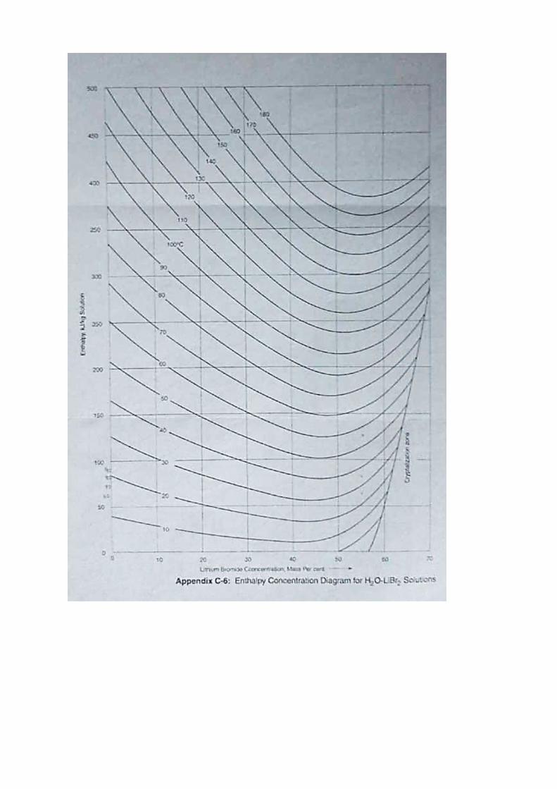
2.2 CRYSTALLIZATIONThe pressure-temperature-mass fraction and enthalpy-temperature-mass fraction charts (Figs.
2.1 and 2.2 ) show lines marked as crystallization in the lower right section. The region to the rightand below these crystallization lines indicates solidification of LiBr salt. In the crystallization regiona two-phase mixture (slush) of water-lithium bromide solution and crystals of pure LiBr exist inequilibrium. The water-lithium bromide system should operate away from the crystallization region asthe formation of solid crystals can block the pipes and valves. Crystallization can occur when the hotsolution rich in LiBr salt is cooled in the solution heat exchanger to low temperatures. To avoid thisthe condenser pressure reduction below a certain value due to say, low cooling water temperature inthe condenser should be avoided. Hence in commercial systems, the condenser pressure is artificiallymaintained high even though the temperature of the available heat sink is low. This actually reducesthe performance of the system, but is necessary for proper operation of the system.
It should be noted from the property charts that the entire water-lithium bromide systemoperates under vacuum.
Fig 2.1 P-T-Conc. Diagram for LiBr- H2O solution

2.3 DESIGN OF A SINGLE-EFFECT LITHIUM BROMIDE AIR CONDITIONING SYSTEM
(fig 2.3 schimatic diagram of experimental setup)
2.3.1 ASSUMPTIONSTo perform estimations of equipment sizing and performance evaluation of single-effect water-
lithium bromide absorption cooler basic assumptions and input values must be considered. the basicassumptions are:
i. The pressure in the evaporator and absorber is assumed to be 0.7 cm of Hg . The pressurein the generator and condenser is assume to be 7 cm of Hg.
ii. the steady state refrigerant is pure water,iii. there are no pressure changes except through the flow restrictors and the pump,iv. Refrigerant at inlet of evaporator is saturated liquid and refrigerant at outlet of the
evaporator is saturated vapour.v. Fouling factors are neglected at both condenser and evaporator.
vi. Thickness of the condenser and evaporator is neglectedvii. the pump is isentropic, and there are no jacket heat losses.
2.3.2 EVAPORATOR HEAT EXCHANGER DESIGNFor the Evaporator Heat Exchanger design the data is shown in the following Table are
considered. These data are extracted to facilitate construction.
The fluid inside the tube is heated by the run of fluid at the outer surface of the tube, so thatprogressive vaporisation occurs. The heat transfer coefficient increases with distance from the entrancesince heat is added continuously to the fluid. It is also not yet possible to predict all of the
E
G
G
A
E
60C
45.830
C
200
C
400
C
7.5CMOFHG
0.1bar
0.7CMOFHG
0.009438Bar
h=2511.48
C
G
A
e
HE
A
320C
350C
60C
60C

characteristics of this process quantitatively because of the great number of variables upon which theprocess depends and the complexity of the various two-phase flow patterns that occur as the quality ofthe vapour-liquid mixture increases during vaporization .Therefore, in the case of this study, theoverall heat transfer coefficient is determined experimentally and finally the evaporator sizing is beingdone by - NTU method.
TABLE 2.1Evaporator Heat Exchanger CharacteristicsParameter Type / ValueHeat Exchanger Type Multi-pass horizontal tubes ( cross flow )
(outside diameter Do = inside diameter Di = 25 mm)Water inlet temperature 6 0CWater outlet temperature 6 0CMass flow rate ( m ) 1.4*10-3 kg/secEvaporator load ( Q ) 3.5 kWEvaporator pressure 0.7 cm of Hg
TABLE 2.2Properties of water and air during evaporating process.
FluidName
Temperature0C
Density Dynamicviscosity. Specific
heat .Thermalconductivity.
Water 6 1000 1.52 ∗ 10 4187 0.5818
Air 35 1.145 1.945 ∗ 10 1005 0.02625
2.3.2.1 CALCULATION OF OVERALL HEAT TRANSFER CO-EFFICIENT (U)
i) FOR INNER HEAR TRANSFER COEFFICIENT (hi):-
Reynolds no of the flow of water inside the copper tubeRe = ρVDμρ = density of water = 1000 kg mV = velocity of flow = mρ ∗ Am = mass flow of water in evaporator tubesm = 210 ∗ Qh = 210 ∗ 12511.65 = . ∗so V = 1.4 ∗ 101000 ∗ π 4 D = 1.4 ∗ 101000 ∗ π 4 0.025 = 2.85 ∗ 10 m sec⁄
so Re = 1000 ∗ 2.85 ∗ 10 ∗ 0.0251.52 ∗ 10 = 46.875μ at 6 c = 1.52 centpoise

prandti no P = µck = 1.52 ∗ 10 ∗ 4.187 ∗ 100.5818 = 10.93c = sp. heat of water = 4187 j kg. kK= thermal conductivity of water at 6 c = 0.5818 w m. kAs the flow is laminar and it is forced convection .so,N = 0.028 ∗ Re . ∗ Prn = 0.4 for heatingSo Nusselt no of flow N = 0.028 ∗ 115.13 . ∗ 10.93 . = 3.24Here flow is fully developed and constant heat flux so Nu=4.363we know N = h Dk=> h = N ∗ kD = 4.363 ∗ 0.58180.025=> = . .ii) FOR OUTER HEAT TRANSFER COEFFICIENT (ho) :-
Reynolds no of flow Re = ρ ∗ V ∗ Dµhere ρ = density of air = 1.145 k mV = velocity of flow of air = 2m sec⁄D = outer diameter of evaporator copper tube = 0.025 mµ = dynamic viscosity of air ,µ at 35 c = 1.945 ∗ 10 N. S mRe = 1.145 ∗ 2 ∗ 0.0251.945 ∗ 10 = 2943.44So the cross turbulent flow in forced convection .Nusselt no , N = C ∗ Re ∗ Pr .TABLE 2.3( value of C and n with respect to the Re value )
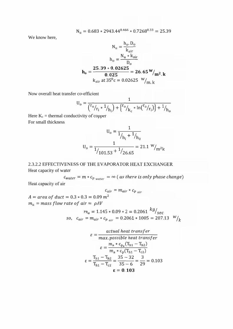
N = 0.683 ∗ 2943.44 . ∗ 0.7268 . = 25.39We know here, N = h . Dkh = N ∗ kD= . ∗ .. = . .k at 35 c = 0.02625 w m. kNow overall heat transfer co-efficientU = 1r r ∗ 1 h + r k ∗ ln r r + 1 hHere Kc = thermal conductivity of copperFor small thickness U = 11 h + 1 hU = 11 101.53 + 1 26.65 = 21.1 w m k2.3.2.2 EFFECTIVENESS OF THE EVAPORATOR HEAT EXCHANGERHeat capacity of water = ∗ = ∞ ( ℎ ℎ ℎ )Heat capacity of air = ∗= = 0.3 ∗ 0.3 = 0.09= == 1.145 ∗ 0.09 ∗ 2 = 0.2061, = ∗ = 0.2061 ∗ 1005 = 207.13
= ℎ. ℎ= m ∗ c (T − T )m ∗ c (T − T )ε = T − TT − T = 35 − 3235 − 6 = 329 = 0.103= .

(fig 2.4 evaporator heat exchanger)
We know for a boiler or condenser ε = 1 − ee = 1 − ε−NTU = ln(1 − ε)−NTU = ln(1 − 0.103)= .We know that NTU = U ∗ AcA = Total area exposed to heat transfer 0.108 = 21.1 ∗ A207.13A = 0.108 ∗ 207.1321.1 = 1.06 m2.3.2.3 LENGTH OF THE COPPER TUBE ( L ):-L = Aπ. DL = 1.06π ∗ 0.025 = .This is the total length of copper tube required for the evaporator design .
350C
60C
320C
60C

2.3.3 CONDENSER HEAT EXCHANGER DESIGNFor the condenser Heat Exchanger design the data is shown in the following Table 2.4 are
considered. These data are extracted to facilitate construction.
The fluid inside the tube is cooled by dipping the heat exchanger tubes in a water tank wherecooling water is at a static position, so that progressive condensation occurs. The heat transfercoefficient decreases with distance from the entrance since heat is removed continuously from thefluid. Therefore, in the case of this study, the overall heat transfer coefficient is determinedexperimentally and finally the evaporator sizing is being done by LMTD method.
Table 2.4 Condenser Heat Exchanger Characteristics tableParameter Type / Value
Heat Exchanger Type Shell and coiled type(outside diameter Do = inside diameter Di = 20 mm)
Water inlet temperature 45.48 0CWater outlet temperature 45.48 0C
Mass flow rate ( m ) 1.46*10-3 kg/secEvaporator load ( Q ) 3.5 kWEvaporator pressure 7 cm of Hg
The rate of heat transfer during the condensation process will be=Here, U=overall heat transfer coefficient=1160 (for steam, copper and water)
A=area exposed to heat transferθ = logarithmic mean temperature differenceA=area exposed to heat transfer
(Fig 2.4 condenser heat exchanger )
45.480C 45.480C
200C
250C

= − = 25 − 2025 20 = 22.40 ℃=> = 3.5 ∗ 101160 ∗ 22.40 = 0.134
2.3.3.1 LENGTH OF CONDENSER TUBE :-
Length of condenser tube = −= = .So the length of condenser tube required will be 2.132 m.
2.3.4 ABSORBER HEAT EXCHANGER DESIGNIn an absorber, the strong solutions, coming from bubble pump, absorb water vapor coming
from the evaporator. In a recent study, a model for absorption of water vapor into aqueous LiBr flowingover a horizontal smooth tube was developed.
Mass balance in absorber m = mass flow rate in evaporatorm = mass flow rate of inlet strong LiBr solutionm = mass flow rate of weak LiBr solution at outlet of absorberm +m = m=> 1.4 ∗ 10 +m = m=> m −m = 1.4 ∗ 10Mass fraction of LiBr2 in absorberX = mass fraction of LiBr at the outlet of evaporaterX = mass fraction of LiBr in weak solutionX = mass fraction of LiBr in strong solution=> m .X +m . X = m . X=> 0.6 ∗ m = m ∗ 0.55
on solving m = 0.0168 kg sec and m = 0.0154 kg secheat absorbed in absorber = m h +m h −m h −mc ∆t= 1.4 ∗ 10 ∗ 2511 + 0.0154 ∗ 100 − 0.0154 ∗ 30= 4.593 kw

2.3.5 GENERATOR HEAT EXCHANGER DESIGNThe weak LiBr solution from the absorber is pumped to the generator by a solution pump.
Before pumping to the generator coils the solution is allowed to pass through a solution through thesolution heat exchanger for the preheating of the weak solution. Generator provides the latent heat ofvaporisation. The latent heat evaporates the water particles from the weak solution . Then the watervapour is allowed to pass through the condenser and the remained strong LiBr solution which containa little amount of water particle goes to absorber tank through the solution heat exchanger.
Table 2.4 Generator Heat Exchanger Characteristics
Parameter Type/ ValueHeat Exchanger Type Induction coil typeGenerator pressure 7 cm of HgGenerator solution Entering: 55% LiBr at 20°C
Leaving: 60% LiBr at 45.83°C
The enthalpy of the inlet weak LiBr solution at 20℃ and 55% (h5)= 50 kJ kgThe enthalpy of strong LiBr solution at 45.83℃ and 60% (h6) =120kJ kgThe enthalpy of saturated steam at 45.83 0C (h1) = 2584.7 kJ kgheat supplied in generator Q = m h +m h −m h= 7.31 ∗ 10 ∗ 2392.94 + 0.0154 ∗ 120 − 0.0168 ∗ 50= .
So the required size of generator for this air conditioning system will be 2.75 kW and it willbe a coil type induction heater.
2.4 PRACTICAL PROBLEMS IN WATER-LITHIUM BROMIDE SYSTEMSPractical problems typical to water-lithium bromide systems are:
i. Crystallizationii. Air leakage
iii. Pressure dropsAs mentioned before to prevent crystallization the condenser pressure has to be maintained at
certain level, irrespective of cooling water temperature. This can be done by regulating the flow rateof cooling water to the condenser. Additives are also added in practical systems to inhibitcrystallization. Since the entire system operates under vacuum, outside air leaks into the system. Hencean air purging system is used in practical systems. Normally a two-stage ejector type purging systemis used to remove air from the system. Since the operating pressures are very small and specific volumeof vapour is very high, pressure drops due to friction should be minimized. This is done by using twin-and single-drum arrangements in commercial systems.

CHAPTER - 3
3.1 CONSTRUCTION OF THE UNIT AND EXPERIMENTAL RESULTSAll heat exchangers described above, are constructed in a way that permits the use of Varying
number of tubes. The objective is to modify the number of heat exchanger tubes and Thus the heatexchange area, until the required operating conditions, depicted in Tables 2.1-2.4, Are obtained. Thiswill ensure a design with a good COP. For this Purpose thermometer pockets and flow-meters areinstalled at various points of the unit for Measurements and adjustments.
3.2 SOLUTION HEAT EXCHANGERThe solution heat exchanger is constructed with the copper pipes specified and is Positioned slightlybelow the generator as indicated in Figure. During operation the solution of the generator is flowingto the absorber by gravity and pressure difference and the flow is Adjusted with a valve. The solutionbeing heated is pumped from the lower pressure of the Absorber to the generator.
3.3 CONCLUSIONThe unit designed is constructed and each heat exchanger is adjusted to the required Output. In
this way the designed COP is ensured. Based on the construction experience of the 3.5kW unit thatcan cover the needs of a typical insulated house .The present cost of the absorption unit together withits running cost is economically viable. Considering also the destruction of the ozone layer caused bythe use of electric chillers, absorption units will offer a better environment, especially if some form ofRenewable or waste energy is used for their operation.