Embed Size (px)
Citation preview
AMERICAS
FRABA Inc.
1800 East State Street, Suite 148
Hamilton, NJ 08609, USA
T +1 609 750-8705, F +1 609 750-8703
www.posital.com, [email protected]
EUROPE
POSITAL GmbH
Carlswerkstrasse 13c
D-51063 Köln, GERMANY
T +49 221 96213-0, F +49 221 96213-20
www.posital.eu, [email protected]
ASIA
FRABA Pte. Ltd.
60 Alexandra Terrace,
#02-05 The Comtech, SINGAPORE 118502
T +65 6514 8880, F +65 6271 1792
www.posital.sg, [email protected]
Absolute Rotary Encoder
with PROFINET-IO-Interface
OCD-EIA1B-XXXX-XXXX-PRM
User Manual
Info UME-EI
Revision 2010-10-27
Page 2
ABSOLUTE ROTARY ENCODER WITH PROFINET INTERFACE
USER MANUAL
Content
Content ............................................................. 2
1. Introduction ................................................. 4
1.1 Absolute rotary encoder ........................... 4
1.2 PROFINET technology ............................ 5
1.3 Features of the Encoder .......................... 5
2. Installation ................................................... 6
2.1 Electrical Connection ............................... 6
2.2 Ethernet cables ........................................ 6
2.3 Diagnostic LEDs ...................................... 7
2.4 Status LED indication ............................... 7
2.5 Instructions for mechanical installation and
electrical connection of the rotary encoder .... 8
3. Device configuration ................................... 9
3.1 Standardization ........................................ 9
3.2 Encoder Classes ...................................... 9
3.3 Encoder functions .................................. 10
3.4 Signal list for Cyclic Data Transmission . 10
3.4.1 Format of actual position values ......... 11
3.4.2 Encoder control word (STW2_ENC) ... 12
3.4.3 Encoder status word (ZSW2_ENC) .... 13
3.4.4 Encoder control word (G1_STW) ........ 13
3.4.5 Encoder status word (G1_ZSW) ......... 14
3.5 Standard + manufacture telegrams ........ 15
3.6 Configuration principle ........................... 17
3.7 Rotary encoder functionality overview ... 17
3.8 Rotary encoder functions – data format . 17
3.9 Parameter for Acyclic Data Transmission
..................................................................... 18
Beginning with GSDML version GSDML-V2.2-
POSITAL-OCD-20100808 it is possible to
change the telegram type without changing
the MAP parameters. ................................... 18
3.9.1 Base Mode Parameter ........................ 19
3.9.2 Device Parameter ............................... 19
3.9.3 Vendor Parameter ............................... 19
3.10 Patronized Parameter .......................... 19
3.11 Rotary encoder function description ..... 22
3.11.1 Code sequence ................................. 22
3.11.2 Class 4 functionality .......................... 23
3.11.3 Preset control for G1_XIST1 ............. 23
3.11.4 Scaling function control ..................... 23
3.11.5 Alarm channel control ....................... 23
3.11.6 Compatibility mode ............................ 23
3.11.7 Preset value ...................................... 24
3.11.7.1 Telegram 81-84 .............................. 24
3.11.7.2 Telegram 860 ................................. 26
3.11.8 Offset value ....................................... 26
3.11.9 Scaling parameters ........................... 26
3.11.10 Max. Master Sign-Of-Life failures .... 26
3.11.11 Velocity measuring units ................. 27
3.11.12 Velocity filter .................................... 27
3.11.13 Endless Shaft (RoundAxis) ............. 27
3.11.14 Encoder Profile version ................... 28
4. Configuring with STEP7 ............................ 29
4.1 Installing the GSDML file ........................ 29
4.2 Engineering a POSITAL encoder into a
STEP7 project .............................................. 30
4.3 Module Access Point Parameter setup : 33
4.4 HW Config IRT-Setup: ........................... 34
4.5 IRT- Topology... ..................................... 37
Info UME-EI
Revision 2010-10-27
Page 3
ABSOLUTE ROTARY ENCODER WITH PROFINET INTERFACE
USER MANUAL
4.6 LLDP (Link Layer Discovery Protocol) ... 37
4.7 SIMOTION SCOUT ................................ 42
5 IRT communication .................................... 50
5.1 IRT settings ............................................ 50
5.2 User data reliability ................................ 50
5.2.1 General ............................................... 50
5.2.2 Controller's Sign-Of-Life (C-LS) .......... 50
5.2.3 DO’s Sign-Of-Life (DO-LS) ................. 52
5.2.4 Counting strategy for the Sign-Of-Life
failure counter .............................................. 54
5.2.5 Error codes in G1_XIST2 .................... 55
5.3 Base Mode Parameter Access .............. 55
5.3.1 General ............................................... 55
5.3.2 General characteristics ....................... 55
5.3.3 DO addressing modes ........................ 56
5.3.4 Parameter requests and parameter
responses .................................................... 56
5.3.5 Coding ................................................. 61
5.3.6 Data flow ............................................. 65
6. Configuring with PC Worx ........................ 66
7 FAQ .............................................................. 72
8 Technical data ............................................. 74
8.1 Electrical data ......................................... 74
8.2 Mechanical data ..................................... 74
8.3 Minimum (mechanical) lifetime ............... 75
8.4 Environmental Conditions ...................... 75
9 Mechanical Drawings ................................. 76
9.1 Synchro Flange (S) ................................ 76
9.2 Clamp Flange (F) ................................... 76
9.3 Hollow shaft (B) ...................................... 77
10 Models / Ordering Description................. 78
11 Accessories and Documentation ............ 79
12 Glossar ...................................................... 80
13 Revision index .......................................... 81
Info UME-EI
Revision 2010-10-27
Page 4
ABSOLUTE ROTARY ENCODER WITH PROFINET INTERFACE
USER MANUAL
Copyright
The company POSITAL GmbH claims copyright on
this documentation. It is not allowed to modify, to
extend, to hand over to a third party and to copy
this documentation without written approval by the
company POSITAL GmbH. Nor is any liability
assumed for damages resulting from the use of the
information contained herein. Further, this
publication and features described herein are
subject to change without notice.
Alterations of specifications reserved
Technical specifications, which are described in
this manual, are subject to change due to our
permanent strive to improve our products.
Disclaimer of Warranty
POSITAL GmbH makes no representations or
warranties, either express or implied, by or with
respect to anything in this manual, and shall not be
liable for any implied warranties of merchantability
and fitness for a particular purpose or for any
indirect, special, or consequential damages.
Version date: October 27, 2010
Version number: 2.09
Article number: n/a
Author: Reiner Bätjer
1. Introduction
This manual describes the implementation and
configuration of an absolute rotary encoder with
PROFINET interface. The device fulfills the
requirements of a PROFINET IO device with RT
(real time) or IRT (isochronous real time)
classification.
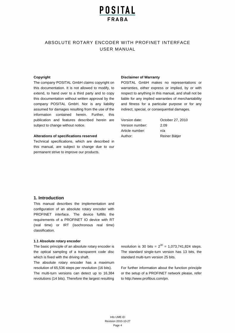
1.1 Absolute rotary encoder
The basic principle of an absolute rotary encoder is
the optical sampling of a transparent code disc
which is fixed with the driving shaft.
The absolute rotary encoder has a maximum
resolution of 65,536 steps per revolution (16 bits).
The multi-turn versions can detect up to 16,384
revolutions (14 bits). Therefore the largest resulting
resolution is 30 bits = 230
= 1,073,741,824 steps.
The standard single-turn version has 13 bits, the
standard multi-turn version 25 bits.
For further information about the function principle
or the setup of a PROFINET network please, refer
to http://www.profibus.com/pn.
Info UME-EI
Revision 2010-10-27
Page 5
ABSOLUTE ROTARY ENCODER WITH PROFINET INTERFACE
USER MANUAL
1.2 PROFINET technology
PROFINET is an Industrial Ethernet standard
merging plant automation with other enterprise IT
resources.
It provides comparable functionality to PROFIBUS
with techniques used by engineering, IT, and
management personnel.
Established IT standards are employed as basis of
communication: TCP, UDP, IP. XML is used as
description language for device profiles (GSDML
files).
Two ways of using PROFINET are available:
PROFINET IO, similar to PROFIBUS DP as a
distributed I/O system and PROFINET CBA as a
modular component-based system for larger
systems.
PROFINET offers scalable communication for
different applications in industrial automation:
PROFINET NRT (non real time) is suited
for non-time-critical process automation
with clock rates of roughly 100 msec.
PROFINET RT (real time) offers a
communication channel with optimized
performance (10 msec clock rate) for
most factory automation tasks
PROFINET IRT (isochronous real time)
employs special communication hardware
to enable clock rates of less than 1 msec
and a jitter precision of less than 1 µsec.
This channel is mainly of use for motion
control applications.
PROFINET IO uses a view of distributed I/O similar
to PROFIBUS DP. IO controllers (e.g. PLCs) run
an automation program, IO devices (e.g. absolute
encoders) are remotely assigned field devices, and
IO supervisors (e.g. programming devices) are
used for commissioning and diagnostics.
The engineering of PROFINET IO is done similar
to PROFIBUS. The field buses (i.e. Ethernet
topologies) are assigned to control systems during
configuration. The IO device is configured in the
actual system based on the contents of its GSDML
file.
After completion of the engineering the installer
loads the data for the expansion into the IO
controller (PLC) and the IO controller assumes
data exchange with the IO device.
An IO device is addressed within PROFINET (and
also possibly by external IT components) through
its IP address.
Data can be exchanged from the IO controller to
the IO device (and vice versa) cyclically (for
process data). Apart from this, parameter data can
be exchanged acyclically during engineering of the
IO device or by the use of PLC programming
blocks.
1.3 Features of the Encoder
Integrated Boot loader for customer
firmware upgrades
Round axis (Endless shaft)
Neighbouring detection
Engineering identification call
Different filters for velocity
Used Profinet Encoder Profile V4.0/V4.1
Info UME-EI
Revision 2010-10-27
Page 6
ABSOLUTE ROTARY ENCODER WITH PROFINET INTERFACE
USER MANUAL
2. Installation
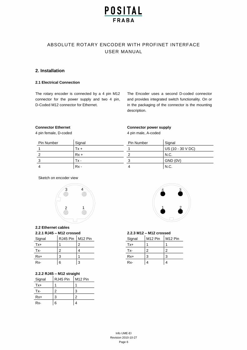
2.1 Electrical Connection
The rotary encoder is connected by a 4 pin M12
connector for the power supply and two 4 pin,
D-Coded M12 connector for Ethernet.
The Encoder uses a second D-coded connector
and provides integrated switch functionality. On or
in the packaging of the connector is the mounting
description.
Connector Ethernet
4 pin female, D-coded
Connector power supply
4 pin male, A-coded
2.2 Ethernet cables
2.2.1 RJ45 – M12 crossed
Signal RJ45 Pin M12 Pin
Tx+ 1 2
Tx- 2 4
Rx+ 3 1
Rx- 6 3
2.2.2 RJ45 – M12 straight
Signal RJ45 Pin M12 Pin
Tx+ 1 1
Tx- 2 3
Rx+ 3 2
Rx- 6 4
2.2.3 M12 – M12 crossed
Signal M12 Pin M12 Pin
Tx+ 1 1
Tx- 2 2
Rx+ 3 3
Rx- 4 4
Pin Number Signal
1 Tx +
2 Rx +
3 Tx -
4 Rx -
Sketch on encoder view
2
3
1
4
Pin Number Signal
1 US (10 - 30 V DC)
2 N.C.
3 GND (0V)
4 N.C.
1
4
2
3
5
Info UME-EI
Revision 2010-10-27
Page 7
ABSOLUTE ROTARY ENCODER WITH PROFINET INTERFACE
USER MANUAL
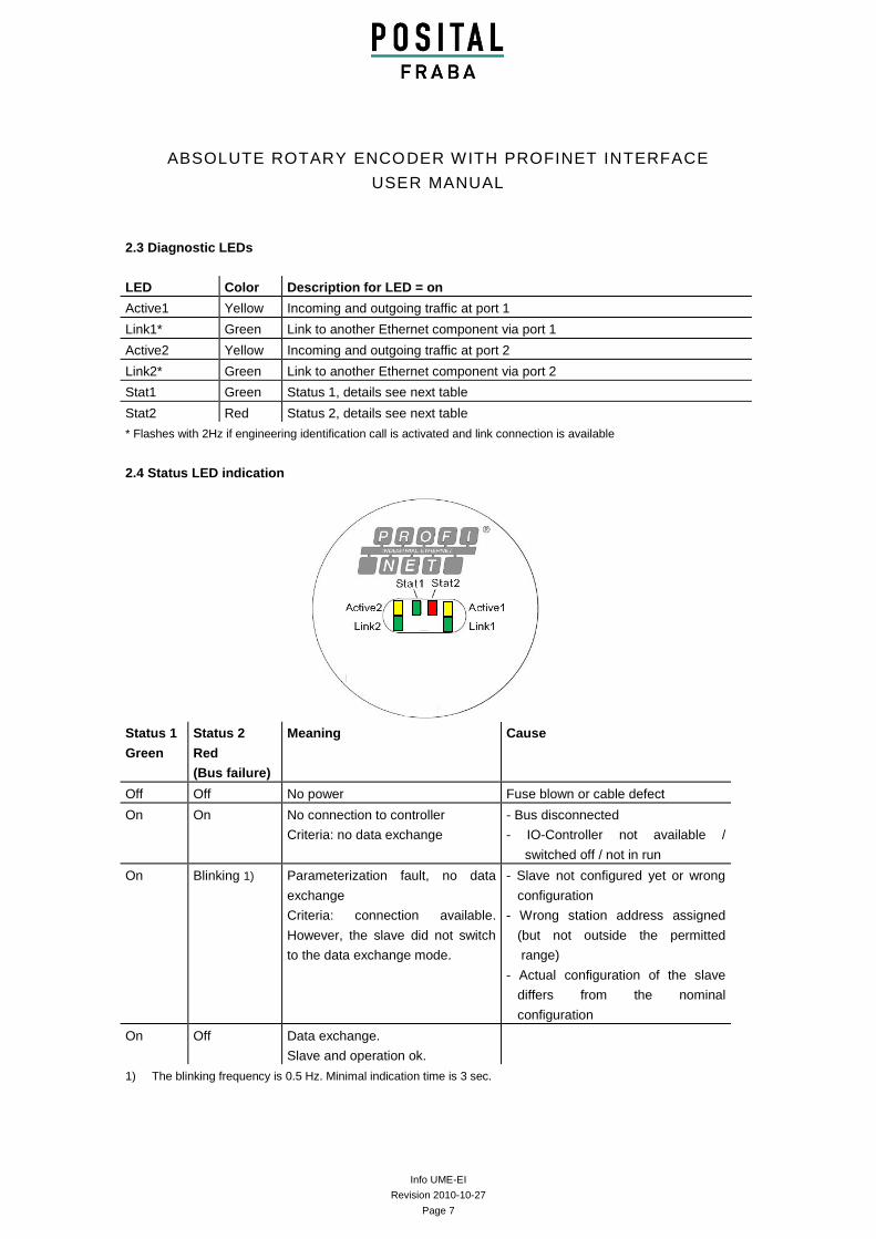
2.3 Diagnostic LEDs
LED Color Description for LED = on
Active1 Yellow Incoming and outgoing traffic at port 1
Link1* Green Link to another Ethernet component via port 1
Active2 Yellow Incoming and outgoing traffic at port 2
Link2* Green Link to another Ethernet component via port 2
Stat1 Green Status 1, details see next table
Stat2 Red Status 2, details see next table
* Flashes with 2Hz if engineering identification call is activated and link connection is available
2.4 Status LED indication
Status 1
Green
Status 2
Red
(Bus failure)
Meaning Cause
Off Off No power Fuse blown or cable defect
On On No connection to controller
Criteria: no data exchange
- Bus disconnected
- IO-Controller not available /
switched off / not in run
On Blinking 1) Parameterization fault, no data
exchange
Criteria: connection available.
However, the slave did not switch
to the data exchange mode.
- Slave not configured yet or wrong
configuration
- Wrong station address assigned
(but not outside the permitted
range)
- Actual configuration of the slave
differs from the nominal
configuration
On Off Data exchange.
Slave and operation ok.
1) The blinking frequency is 0.5 Hz. Minimal indication time is 3 sec.
Info UME-EI
Revision 2010-10-27
Page 8
ABSOLUTE ROTARY ENCODER WITH PROFINET INTERFACE
USER MANUAL
2.5 Instructions for mechanical installation and electrical connection of the rotary encoder
The following points should be observed:
Do not drop the angular encoder or
subject it to excessive vibration. The
encoder is a precision device.
Do not open the angular encoder
housing. If the device is opened and
closed again, it can be damaged and dirt
may enter the unit.
The angular encoder shaft must be
connected to the shaft to be measured
through a suitable coupling (full shaft
version). This coupling is used to dampen
vibrations and imbalance on the encoder
shaft and to avoid inadmissible high
forces. Suitable couplings are available
from Posital.
Although Posital absolute encoders are
rugged, when used in tough ambient
conditions, they should be protected
against damage using suitable protective
measures. The encoder should not be
used as handles or steps.
Only qualified personnel may commission
and operate these devices. These are
personnel who are authorized to
commission, ground and tag devices,
systems and circuits according to the
current state of safety technology.
It is not permissible to make any electrical
changes to the encoder.
Route the connecting cable to the angular
encoder at a considerable distance or
completely separated from power cables
with their associated noise. Completely
shielded cables must be used for reliable
data transfer and good grounding must be
provided. Cabling, establishing and
interrupting electrical connections may
only be carried-out when the equipment is
in a no-voltage condition. Short-circuits,
voltage spikes etc. can result in erroneous
functions and uncontrolled statuses which
can even include severe personnel injury
and material damage.
The encoder should have got a large-area
connection to PE. If the flange don’t have
a good electrical connection to the
machine – i.e. if there was used a plastic
mounting device – then use i.e. a 30cm
long and 2cm wide copper tape to get the
PE connection.
Before powering-up the system, check all of the
electrical connections. Connections, which are not
correct, can cause the system to function
incorrectly. Fault connections can result in severe
personnel injury and material damage.
Info UME-EI
Revision 2010-10-27
Page 9
ABSOLUTE ROTARY ENCODER WITH PROFINET INTERFACE
USER MANUAL
3. Device configuration
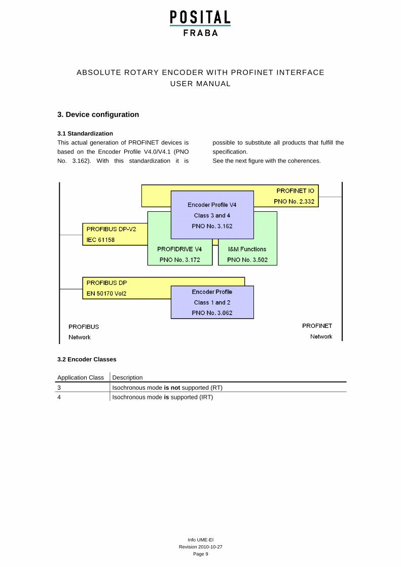
3.1 Standardization
This actual generation of PROFINET devices is
based on the Encoder Profile V4.0/V4.1 (PNO
No. 3.162). With this standardization it is
possible to substitute all products that fulfill the
specification.
See the next figure with the coherences.
3.2 Encoder Classes
Application Class Description
3 Isochronous mode is not supported (RT)
4 Isochronous mode is supported (IRT)
Info UME-EI
Revision 2010-10-27
Page 10
ABSOLUTE ROTARY ENCODER WITH PROFINET INTERFACE
USER MANUAL
3.3 Encoder functions
Implementation
Function Class 3 Class 4
Code sequence -/*
Class 4 functionality
G1_XIST1 Preset control -/*
Scaling function control -/*
Alarm channel control
Preset value -/*
Preset value 64bit - -
Measuring units per revolution / Measuring step -/*
Total measuring range -/*
Measuring units per revolution 64bit -/*
Total measuring range 64bit -/*
Maximum Master Sign-Of-Life failures -/*
Velocity measuring unit -/*
Encoder Profile version
Operating time - -
Offset value -/*
Offset value 64 bit -/*
Round axis (Endless shaft)
Velocity filter
* If Class 4 functionality is activated
3.4 Signal list for Cyclic Data Transmission
Signal No.
Significance Abbreviation Length (bit) Sign
3 Master’s sign-of-life STW2_ENC 16 -
4 Slave’s sign of life ZSW2_ENC 16 -
6 Velocity value A NIST_A 16
8 Velocity value B NIST_B 32
9 Control word G1_STW 16 -
10 Status word G1_ZSW 16 -
11 Position value 1 G1_XIST1 32 -
12 Position value 2 G1_XIST2 32 -
39 Position value 3 G1_XIST3 64 -
Info UME-EI
Revision 2010-10-27
Page 11
ABSOLUTE ROTARY ENCODER WITH PROFINET INTERFACE
USER MANUAL
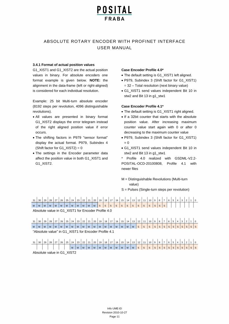
3.4.1 Format of actual position values
G1_XIST1 and G1_XIST2 are the actual position
values in binary. For absolute encoders one
format example is given below. NOTE: the
alignment in the data-frame (left or right-aligned)
is considered for each individual resolution.
Example: 25 bit Multi-turn absolute encoder
(8192 steps per revolution, 4096 distinguishable
revolutions).
All values are presented in binary format
G1_XIST2 displays the error telegram instead
of the right aligned position value if error
occurs.
The shifting factors in P979 "sensor format"
display the actual format. P979, Subindex 4
(Shift factor for G1_XIST2) = 0
The settings in the Encoder parameter data
affect the position value in both G1_XIST1 and
G1_XIST2.
Case Encoder Profile 4.0*
The default setting is G1_XIST1 left aligned.
P979, Subindex 3 (Shift factor for G1_XIST1)
= 32 – Total resolution (next binary value)
G1_XIST1 send values independent Bit 10 in
stw2 and Bit 13 in g1_stw1
Case Encoder Profile 4.1*
The default setting is G1_XIST1 right aligned.
If a 32bit counter that starts with the absolute
position value. After increasing maximum
counter value start again with 0 or after 0
decreasing to the maximum counter value
P979, Subindex 3 (Shift factor for G1_XIST1)
= 0
G1_XIST1 send values independent Bit 10 in
stw2 and Bit 13 in g1_stw1
* Profile 4.0 realized with GSDML-V2.2-
POSITAL-OCD-20100808, Profile 4.1 with
newer files
M = Distinguishable Revolutions (Multi-turn
value)
S = Pulses (Single-turn steps per revolution)
31 30 29 28 27 26 25 24 23 22 21 20 19 18 17 16 15 14 13 12 11 10 9 8 7 6 5 4 3 2 1 0
M M M M M M M M M M M M S S S S S S S S S S S S S
Absolute value in G1_XIST1 for Encoder Profile 4.0
31 30 29 28 27 26 25 24 23 22 21 20 19 18 17 16 15 14 13 12 11 10 9 8 7 6 5 4 3 2 1 0
M M M M M M M M M M M M M M M M M M M S S S S S S S S S S S S S
“Absolute value” in G1_XIST1 for Encoder Profile 4.1
31 30 29 28 27 26 25 24 23 22 21 20 19 18 17 16 15 14 13 12 11 10 9 8 7 6 5 4 3 2 1 0
M M M M M M M M M M M M S S S S S S S S S S S S S
Absolute value in G1_XIST2
Info UME-EI
Revision 2010-10-27
Page 12
ABSOLUTE ROTARY ENCODER WITH PROFINET INTERFACE
USER MANUAL
G1_XIST3
For 64bit position values is the G1_XIST3 available. The binary value will transmit right aligned and
without shifting factor.
IO Data 1 2 3 4
Format 64 bit position value
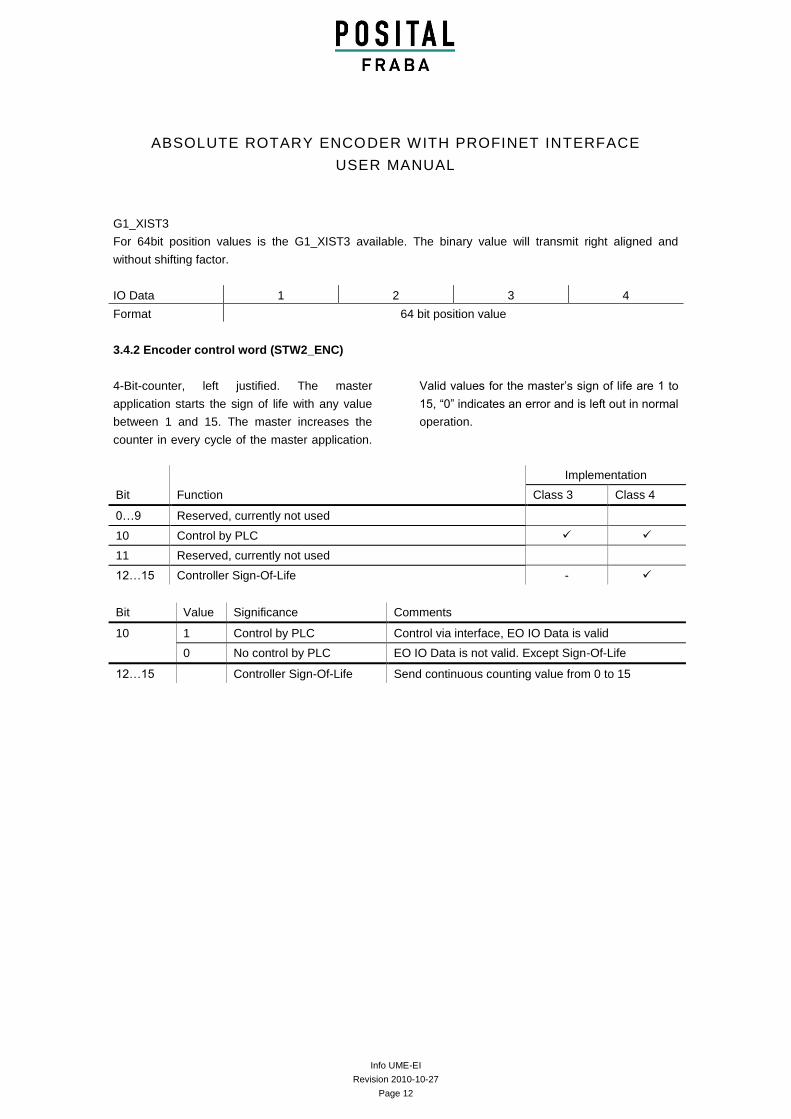
3.4.2 Encoder control word (STW2_ENC)
4-Bit-counter, left justified. The master
application starts the sign of life with any value
between 1 and 15. The master increases the
counter in every cycle of the master application.
Valid values for the master’s sign of life are 1 to
15, “0” indicates an error and is left out in normal
operation.
Implementation
Bit Function Class 3 Class 4
0…9 Reserved, currently not used
10 Control by PLC
11 Reserved, currently not used
12…15 Controller Sign-Of-Life -
Bit Value Significance Comments
10 1 Control by PLC Control via interface, EO IO Data is valid
0 No control by PLC EO IO Data is not valid. Except Sign-Of-Life
12…15 Controller Sign-Of-Life Send continuous counting value from 0 to 15
Info UME-EI
Revision 2010-10-27
Page 13
ABSOLUTE ROTARY ENCODER WITH PROFINET INTERFACE
USER MANUAL
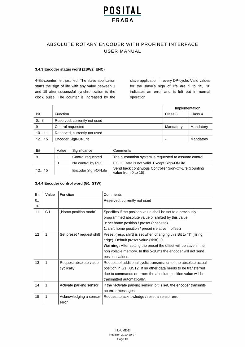
3.4.3 Encoder status word (ZSW2_ENC)
4-Bit-counter, left justified. The slave application
starts the sign of life with any value between 1
and 15 after successful synchronization to the
clock pulse. The counter is increased by the
slave application in every DP-cycle. Valid values
for the slave’s sign of life are 1 to 15, “0”
indicates an error and is left out in normal
operation.
Implementation
Bit Function Class 3 Class 4
0…8 Reserved, currently not used
9 Control requested Mandatory Mandatory
10…11 Reserved, currently not used
12…15 Encoder Sign-Of-Life - Mandatory
Bit Value Significance Comments
9 1 Control requested The automation system is requested to assume control
0 No control by PLC EO IO Data is not valid. Except Sign-Of-Life
12…15 Encoder Sign-Of-Life Send back continuous Controller Sign-Of-Life (counting value from 0 to 15)
3.4.4 Encoder control word (G1_STW)
Bit Value Function Comments
0..
10
Reserved, currently not used
11 0/1 „Home position mode“ Specifies if the position value shall be set to a previously
programmed absolute value or shifted by this value.
0: set home position / preset (absolute)
1: shift home position / preset (relative = offset)
12 1 Set preset / request shift Preset (resp. shift) is set when changing this Bit to “1” (rising
edge). Default preset value (shift): 0
Warning: After setting the preset the offset will be save in the
non volatile memory. In this 5-10ms the encoder will not send
position values.
13 1 Request absolute value
cyclically
Request of additional cyclic transmission of the absolute actual
position in G1_XIST2. If no other data needs to be transferred
due to commands or errors the absolute position value will be
transmitted automatically.
14 1 Activate parking sensor If the “activate parking sensor” bit is set, the encoder transmits
no error messages.
15 1 Acknowledging a sensor
error
Request to acknowledge / reset a sensor error
Info UME-EI
Revision 2010-10-27
Page 14
ABSOLUTE ROTARY ENCODER WITH PROFINET INTERFACE
USER MANUAL
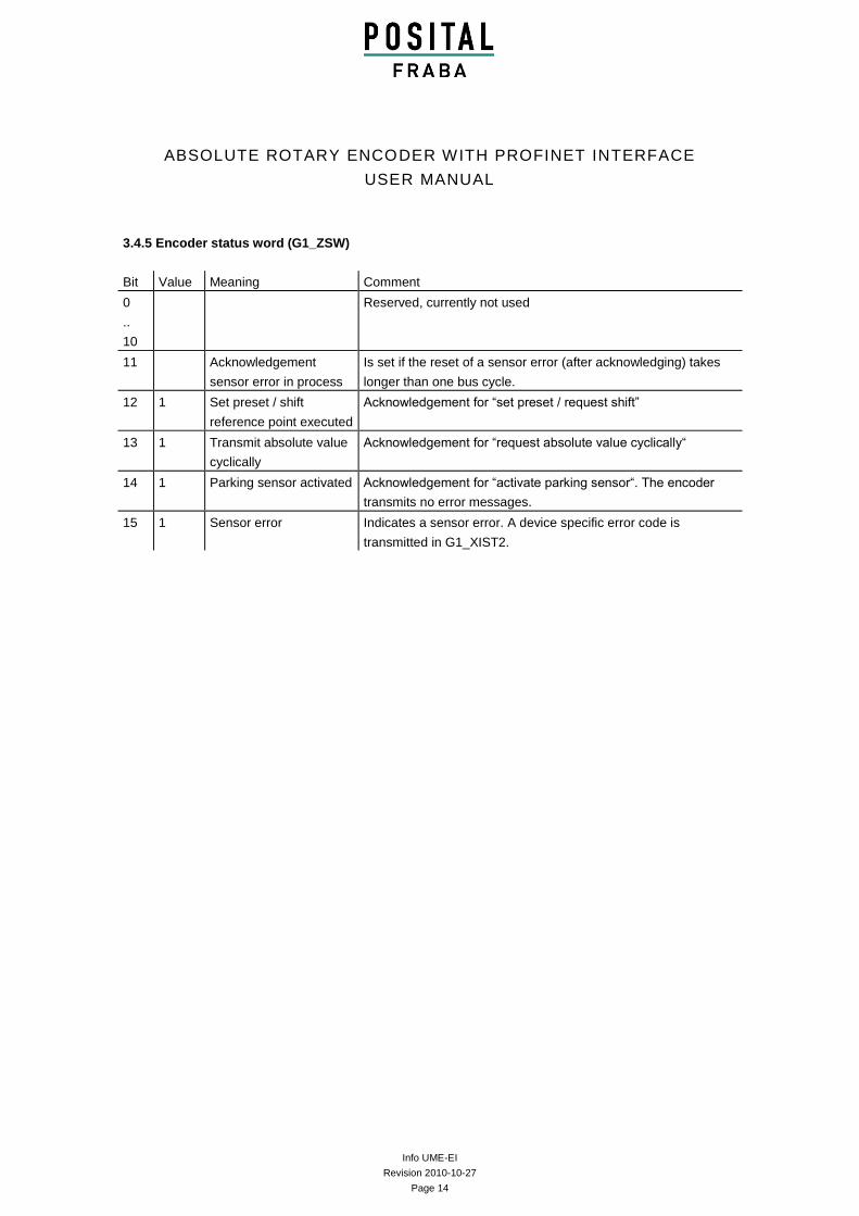
3.4.5 Encoder status word (G1_ZSW)
Bit Value Meaning Comment
0
..
10
Reserved, currently not used
11 Acknowledgement
sensor error in process
Is set if the reset of a sensor error (after acknowledging) takes
longer than one bus cycle.
12 1 Set preset / shift
reference point executed
Acknowledgement for “set preset / request shift”
13 1 Transmit absolute value
cyclically
Acknowledgement for “request absolute value cyclically“
14 1 Parking sensor activated Acknowledgement for “activate parking sensor“. The encoder
transmits no error messages.
15 1 Sensor error Indicates a sensor error. A device specific error code is
transmitted in G1_XIST2.
Info UME-EI
Revision 2010-10-27
Page 15
ABSOLUTE ROTARY ENCODER WITH PROFINET INTERFACE
USER MANUAL
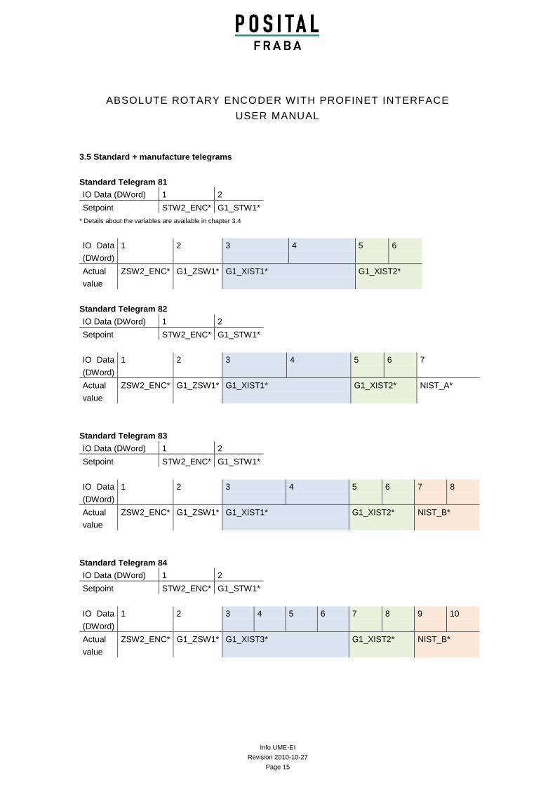
3.5 Standard + manufacture telegrams
Standard Telegram 81
IO Data (DWord) 1 2
Setpoint STW2_ENC* G1_STW1*
* Details about the variables are available in chapter 3.4
IO Data
(DWord)
1 2 3 4 5 6
Actual
value
ZSW2_ENC* G1_ZSW1* G1_XIST1* G1_XIST2*
Standard Telegram 82
IO Data (DWord) 1 2
Setpoint STW2_ENC* G1_STW1*
IO Data
(DWord)
1 2 3 4 5 6 7
Actual
value
ZSW2_ENC* G1_ZSW1* G1_XIST1* G1_XIST2* NIST_A*
Standard Telegram 83
IO Data (DWord) 1 2
Setpoint STW2_ENC* G1_STW1*
IO Data
(DWord)
1 2 3 4 5 6 7 8
Actual
value
ZSW2_ENC* G1_ZSW1* G1_XIST1* G1_XIST2* NIST_B*
Standard Telegram 84
IO Data (DWord) 1 2
Setpoint STW2_ENC* G1_STW1*
IO Data
(DWord)
1 2 3 4 5 6 7 8 9 10
Actual
value
ZSW2_ENC* G1_ZSW1* G1_XIST3* G1_XIST2* NIST_B*
Info UME-EI
Revision 2010-10-27
Page 16
ABSOLUTE ROTARY ENCODER WITH PROFINET INTERFACE
USER MANUAL
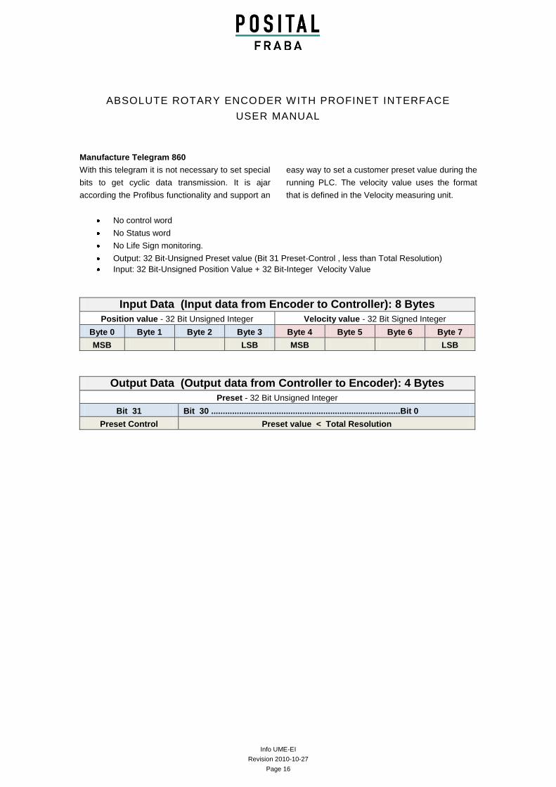
Manufacture Telegram 860
With this telegram it is not necessary to set special
bits to get cyclic data transmission. It is ajar
according the Profibus functionality and support an
easy way to set a customer preset value during the
running PLC. The velocity value uses the format
that is defined in the Velocity measuring unit.
No control word
No Status word
No Life Sign monitoring.
Output: 32 Bit-Unsigned Preset value (Bit 31 Preset-Control , less than Total Resolution)
Input: 32 Bit-Unsigned Position Value + 32 Bit-Integer Velocity Value
Input Data (Input data from Encoder to Controller): 8 Bytes
Position value - 32 Bit Unsigned Integer Velocity value - 32 Bit Signed Integer
Byte 0 Byte 1 Byte 2 Byte 3 Byte 4 Byte 5 Byte 6 Byte 7
MSB LSB MSB LSB
Output Data (Output data from Controller to Encoder): 4 Bytes
Preset - 32 Bit Unsigned Integer
Bit 31 Bit 30 .................................................................................Bit 0
Preset Control Preset value < Total Resolution
Info UME-EI
Revision 2010-10-27
Page 17
ABSOLUTE ROTARY ENCODER WITH PROFINET INTERFACE
USER MANUAL
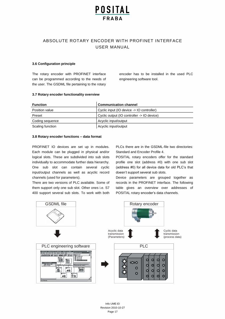
3.6 Configuration principle
The rotary encoder with PROFINET interface
can be programmed according to the needs of
the user. The GSDML file pertaining to the rotary
encoder has to be installed in the used PLC
engineering software tool.
3.7 Rotary encoder functionality overview
Function Communication channel
Position value Cyclic input (IO device -> IO controller)
Preset Cyclic output (IO controller -> IO device)
Coding sequence Acyclic input/output
Scaling function Acyclic input/output
3.8 Rotary encoder functions – data format
PROFINET IO devices are set up in modules.
Each module can be plugged in physical and/or
logical slots. These are subdivided into sub slots
individually to accommodate further data hierarchy.
One sub slot can contain several cyclic
input/output channels as well as acyclic record
channels (used for parameters).
There are two versions of PLC available. Some of
them support only one sub slot. Other ones i.e. S7
400 support several sub slots. To work with both
PLCs there are in the GSDML-file two directories:
Standard and Encoder Profile 4.
POSITAL rotary encoders offer for the standard
profile one slot (address #0) with one sub slot
(address #0) for all device data for old PLC’s that
doesn’t support several sub slots.
Device parameters are grouped together as
records in the PROFINET interface. The following
table gives an overview over addresses of
POSITAL rotary encoder’s data channels.
GSDML file
PLC engineering software PLC
Rotary encoder
Cyclic data transmission (process data)
Acyclic data transmission (Parameters)
Info UME-EI
Revision 2010-10-27
Page 18
ABSOLUTE ROTARY ENCODER WITH PROFINET INTERFACE
USER MANUAL
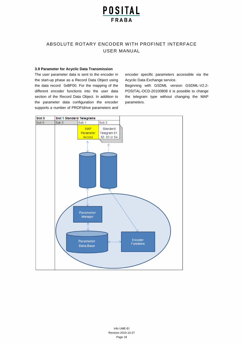
3.9 Parameter for Acyclic Data Transmission
The user parameter data is sent to the encoder in
the start-up phase as a Record Data Object using
the data record 0xBF00. For the mapping of the
different encoder functions into the user data
section of the Record Data Object. In addition to
the parameter data configuration the encoder
supports a number of PROFIdrive parameters and
encoder specific parameters accessible via the
Acyclic Data Exchange service.
Beginning with GSDML version GSDML-V2.2-
POSITAL-OCD-20100808 it is possible to change
the telegram type without changing the MAP
parameters.
Info UME-EI
Revision 2010-10-27
Page 19
ABSOLUTE ROTARY ENCODER WITH PROFINET INTERFACE
USER MANUAL
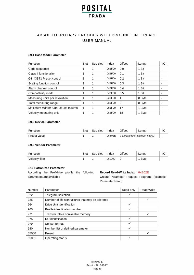
3.9.1 Base Mode Parameter
Function Slot Sub slot Index Offset Length IO
Code sequence 1 1 0xBF00 0.0 1 Bit -
Class 4 functionality 1 1 0xBF00 0.1 1 Bit -
G1_XIST1 Preset control 1 1 0xBF00 0.2 1 Bit -
Scaling function control 1 1 0xBF00 0.3 1 Bit -
Alarm channel control 1 1 0xBF00 0.4 1 Bit -
Compatibility mode 1 1 0xBF00 0.5 1 Bit -
Measuring units per revolution 1 1 0xBF00 1 8 Byte -
Total measuring range 1 1 0xBF00 9 8 Byte -
Maximum Master Sign-Of-Life failures 1 1 0xBF00 17 1 Byte -
Velocity measuring unit 1 1 0xBF00 18 1 Byte -
3.9.2 Device Parameter
Function Slot Sub slot Index Offset Length IO
Preset value 1 1 0xB02E Via Parameter Number 65000 -
3.9.3 Vendor Parameter
Function Slot Sub slot Index Offset Length IO
Velocity filter 1 1 0x1000 0 1 Byte -
3.10 Patronized Parameter
According the Profidrive profile the following
parameters are available
Record Read-Write Index : 0xB02E
Create Parameter Request Program: (example:
Parameter Read)
Number Parameter Read only Read/Write
922 Telegram selection
925 Number of life sign failures that may be tolerated
964 Drive Unit identification
965 Profile identification number
971 Transfer into a nonvolatile memory
975 DO identification
979 Sensor format
980 Number list of defined parameter
65000 Preset
65001 Operating status
Info UME-EI
Revision 2010-10-27
Page 20
ABSOLUTE ROTARY ENCODER WITH PROFINET INTERFACE
USER MANUAL
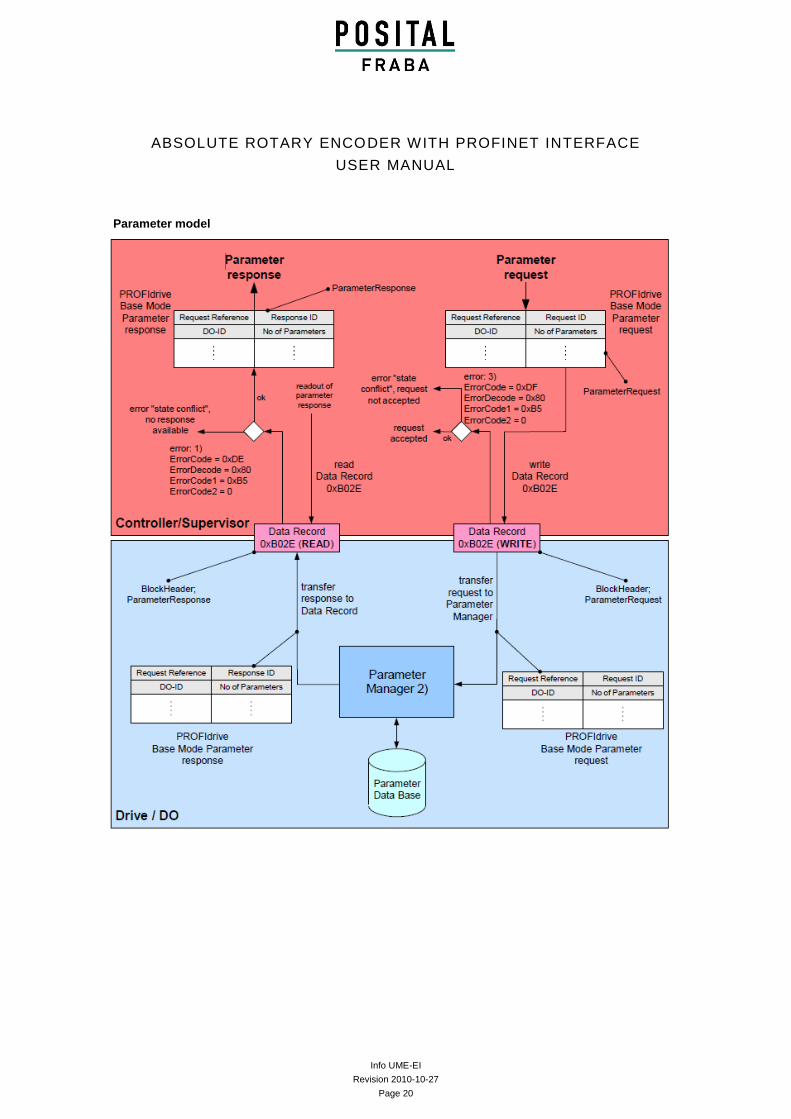
Parameter model
Info UME-EI
Revision 2010-10-27
Page 21
ABSOLUTE ROTARY ENCODER WITH PROFINET INTERFACE
USER MANUAL
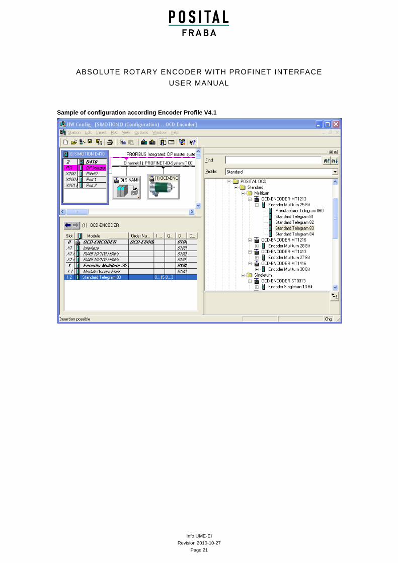
Sample of configuration according Encoder Profile V4.1
Info UME-EI
Revision 2010-10-27
Page 22
ABSOLUTE ROTARY ENCODER WITH PROFINET INTERFACE
USER MANUAL
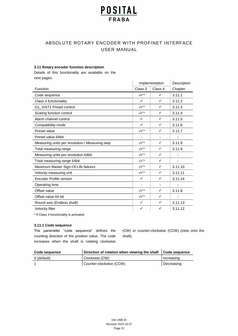
3.11 Rotary encoder function description
Details of this functionality are available on the
next pages.
Implementation Description
Function Class 3 Class 4 Chapter
Code sequence -/* 3.11.1
Class 4 functionality 3.11.2
G1_XIST1 Preset control -/* 3.11.3
Scaling function control -/* 3.11.4
Alarm channel control 3.11.5
Compatibility mode 3.11.6
Preset value -/* 3.11.7
Preset value 64bit - - -
Measuring units per revolution / Measuring step -/* 3.11.9
Total measuring range -/* 3.11.9
Measuring units per revolution 64bit -/* -
Total measuring range 64bit -/* -
Maximum Master Sign-Of-Life failures -/* 3.11.10
Velocity measuring unit -/* 3.11.11
Encoder Profile version 3.11.14
Operating time - - -
Offset value -/* 3.11.8
Offset value 64 bit -/* -
Round axis (Endless shaft) 3.11.13
Velocity filter 3.11.12
* If Class 4 functionality is activated
3.11.1 Code sequence
The parameter “code sequence“ defines the
counting direction of the position value. The code
increases when the shaft is rotating clockwise
(CW) or counter-clockwise (CCW) (view onto the
shaft).
Code sequence Direction of rotation when viewing the shaft Code sequence
0 (default) Clockwise (CW) Increasing
1 Counter-clockwise (CCW) Decreasing
Info UME-EI
Revision 2010-10-27
Page 23
ABSOLUTE ROTARY ENCODER WITH PROFINET INTERFACE
USER MANUAL
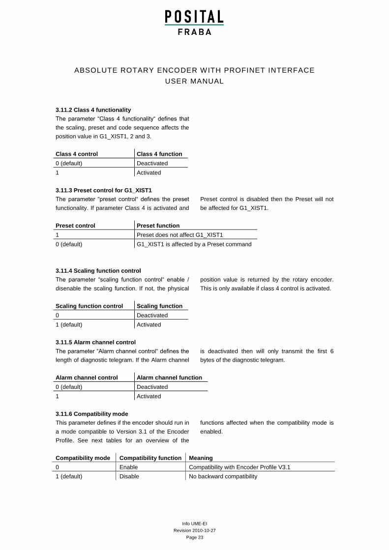
3.11.2 Class 4 functionality
The parameter “Class 4 functionality“ defines that
the scaling, preset and code sequence affects the
position value in G1_XIST1, 2 and 3.
Class 4 control Class 4 function
0 (default) Deactivated
1 Activated
3.11.3 Preset control for G1_XIST1
The parameter “preset control“ defines the preset
functionality. If parameter Class 4 is activated and
Preset control is disabled then the Preset will not
be affected for G1_XIST1.
Preset control Preset function
1 Preset does not affect G1_XIST1
0 (default) G1_XIST1 is affected by a Preset command
3.11.4 Scaling function control
The parameter “scaling function control“ enable /
disenable the scaling function. If not, the physical
position value is returned by the rotary encoder.
This is only available if class 4 control is activated.
Scaling function control Scaling function
0 Deactivated
1 (default) Activated
3.11.5 Alarm channel control
The parameter “Alarm channel control“ defines the
length of diagnostic telegram. If the Alarm channel
is deactivated then will only transmit the first 6
bytes of the diagnostic telegram.
Alarm channel control Alarm channel function
0 (default) Deactivated
1 Activated
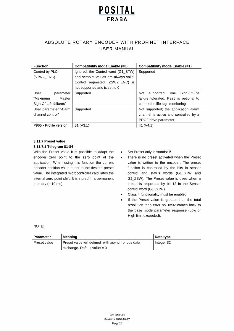
3.11.6 Compatibility mode
This parameter defines if the encoder should run in
a mode compatible to Version 3.1 of the Encoder
Profile. See next tables for an overview of the
functions affected when the compatibility mode is
enabled.
Compatibility mode Compatibility function Meaning
0 Enable Compatibility with Encoder Profile V3.1
1 (default) Disable No backward compatibility
Info UME-EI
Revision 2010-10-27
Page 24
ABSOLUTE ROTARY ENCODER WITH PROFINET INTERFACE
USER MANUAL
Function Compatibility mode Enable (=0) Compatibility mode Enable (=1)
Control by PLC
(STW2_ENC)
Ignored; the Control word (G1_STW)
and setpoint values are always valid.
Control requested (ZSW2_ENC) is
not supported and is set to 0
Supported
User parameter
“Maximum Master
Sign-Of-Life failures”
Supported Not supported; one Sign-Of-Life
failure tolerated, P925 is optional to
control the life sign monitoring
User parameter “Alarm
channel control”
Supported Not supported; the application alarm
channel is active and controlled by a
PROFIdrive parameter
P965 - Profile version 31 (V3.1) 41 (V4.1)
3.11.7 Preset value
3.11.7.1 Telegram 81-84
With the Preset value it is possible to adapt the
encoder zero point to the zero point of the
application. When using this function the current
encoder position value is set to the desired preset
value. The integrated microcontroller calculates the
internal zero point shift. It is stored in a permanent
memory (~ 10 ms).
NOTE:
Set Preset only in standstill!
There is no preset activated when the Preset
value is written to the encoder. The preset
function is controlled by the bits in sensor
control and status words (G1_STW and
G1_ZSW). The Preset value is used when a
preset is requested by bit 12 in the Sensor
control word (G1_STW).
Class 4 functionality must be enabled!
If the Preset value is greater than the total
resolution then error no. 0x02 comes back to
the base mode parameter response (Low or
High limit exceeded).
Parameter Meaning Data type
Preset value Preset value will defined with asynchronous data
exchange. Default value = 0
Integer 32
Info UME-EI
Revision 2010-10-27
Page 25
ABSOLUTE ROTARY ENCODER WITH PROFINET INTERFACE
USER MANUAL
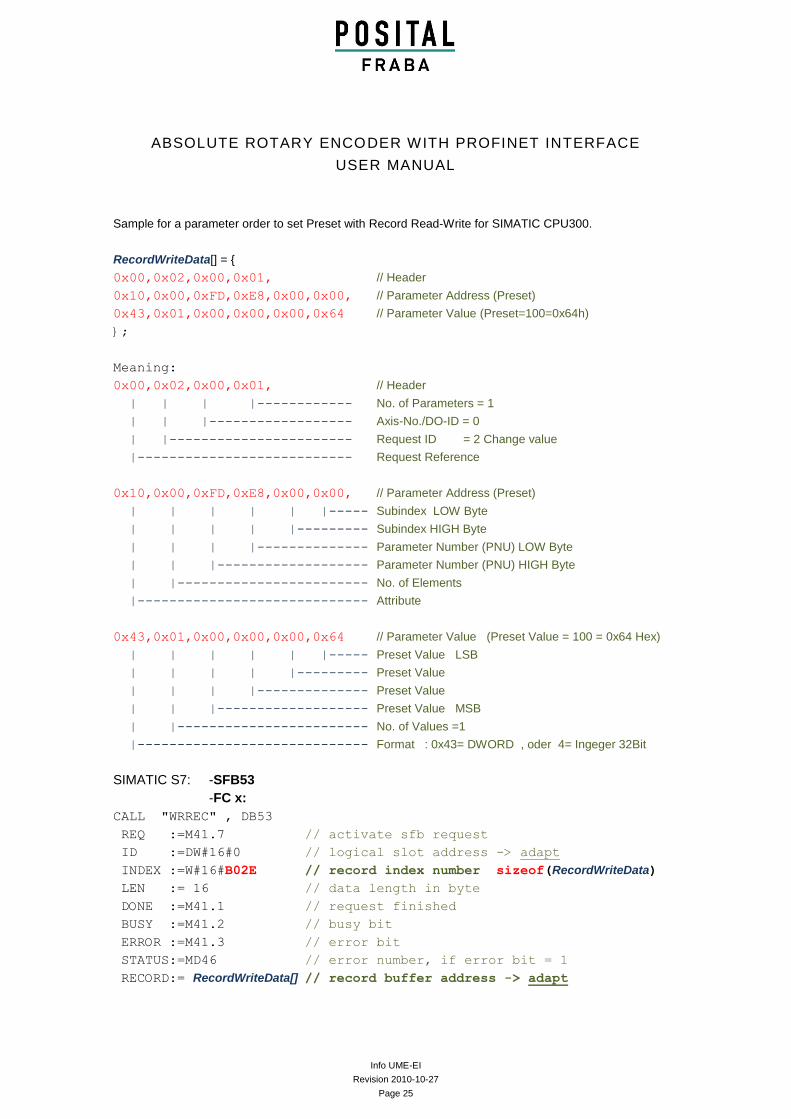
Sample for a parameter order to set Preset with Record Read-Write for SIMATIC CPU300.
RecordWriteData[] = {
0x00,0x02,0x00,0x01, // Header
0x10,0x00,0xFD,0xE8,0x00,0x00, // Parameter Address (Preset)
0x43,0x01,0x00,0x00,0x00,0x64 // Parameter Value (Preset=100=0x64h)
};
Meaning:
0x00,0x02,0x00,0x01, // Header
| | | |------------ No. of Parameters = 1
| | |------------------ Axis-No./DO-ID = 0
| |----------------------- Request ID = 2 Change value
|--------------------------- Request Reference
0x10,0x00,0xFD,0xE8,0x00,0x00, // Parameter Address (Preset)
| | | | | |----- Subindex LOW Byte
| | | | |--------- Subindex HIGH Byte
| | | |-------------- Parameter Number (PNU) LOW Byte
| | |------------------- Parameter Number (PNU) HIGH Byte
| |------------------------ No. of Elements
|----------------------------- Attribute
0x43,0x01,0x00,0x00,0x00,0x64 // Parameter Value (Preset Value = 100 = 0x64 Hex)
| | | | | |----- Preset Value LSB
| | | | |--------- Preset Value
| | | |-------------- Preset Value
| | |------------------- Preset Value MSB
| |------------------------ No. of Values =1
|----------------------------- Format : 0x43= DWORD , oder 4= Ingeger 32Bit
SIMATIC S7: -SFB53
-FC x:
CALL "WRREC" , DB53
REQ :=M41.7 // activate sfb request
ID :=DW#16#0 // logical slot address -> adapt
INDEX :=W#16#B02E // record index number sizeof(RecordWriteData)
LEN := 16 // data length in byte
DONE :=M41.1 // request finished
BUSY :=M41.2 // busy bit
ERROR :=M41.3 // error bit
STATUS:=MD46 // error number, if error bit = 1
RECORD:= RecordWriteData[] // record buffer address -> adapt
Info UME-EI
Revision 2010-10-27
Page 26
ABSOLUTE ROTARY ENCODER WITH PROFINET INTERFACE
USER MANUAL
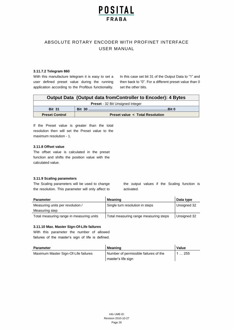
3.11.7.2 Telegram 860
With this manufacture telegram it is easy to set a
user defined preset value during the running
application according to the Profibus functionality.
In this case set bit 31 of the Output Data to “1” and
then back to “0”. For a different preset value than 0
set the other bits.
Output Data (Output data fromController to Encoder): 4 Bytes
Preset - 32 Bit Unsigned Integer
Bit 31 Bit 30 .................................................................................Bit 0
Preset Control Preset value < Total Resolution
If the Preset value is greater than the total
resolution then will set the Preset value to the
maximum resolution - 1.
3.11.8 Offset value
The offset value is calculated in the preset
function and shifts the position value with the
calculated value.
3.11.9 Scaling parameters
The Scaling parameters will be used to change
the resolution. This parameter will only affect to
the output values if the Scaling function is
activated.
Parameter Meaning Data type
Measuring units per revolution /
Measuring step
Single turn resolution in steps Unsigned 32
Total measuring range in measuring units Total measuring range measuring steps Unsigned 32
3.11.10 Max. Master Sign-Of-Life failures
With this parameter the number of allowed
failures of the master’s sign of life is defined.
Parameter Meaning Value
Maximum Master Sign-Of-Life failures Number of permissible failures of the
master’s life sign
1 … 255
Info UME-EI
Revision 2010-10-27
Page 27
ABSOLUTE ROTARY ENCODER WITH PROFINET INTERFACE
USER MANUAL
3.11.11 Velocity measuring units
This parameter defines the coding of velocity
measuring units used to configure the values
NIST_A and NIST_B. Only Telegrams 82-84
uses the velocity outputs.
With each cycle will calculate the velocity from
the position value. To get a high velocity
precision it is necessary to use a short cycle
time.
Velocity measuring unit Value
Steps/s 0
Steps/100ms 1
Steps/10ms 2
RPM 3
3.11.12 Velocity filter
The velocity value can used with three different
exponential moving average filter types.
Default: Fine
Parameter Meaning Data type
Velocity filter Select for the parameter Fine, Normal, Coarse Integer 32
Ratio between old and actual velocity value:
Fine: 7:3
Normal: 96:4
Coarse: 996:4
3.11.13 Endless Shaft (RoundAxis)
Normally the period, i.e. “Total resolution” /
“measuring units” per revolution must be an integer
and it must fit an integer number of times (integer
multiple) into 4096 for an encoder with 12 Bit for
the revolutions. This means that i.e. 100 or 325
revolutions could make trouble. So the following
equation must apply:
(4096 x measuring units per revolution) / Total resolution = integer
But this Profinet encoder solves this problem
automatically. The encoder checks if the
parameters need the endless shaft and activates
the functionality by self.
Note: The internal software routine only works if
the encoder is in operation. If it is necessary to turn
the encoder shaft more than 1024 revolutions
without power supply this can lead to problems
(the internal routine will not work without power
supply). With this function there will be save
additional values in the internal eeprom.

Info UME-EI
Revision 2010-10-27
Page 28
ABSOLUTE ROTARY ENCODER WITH PROFINET INTERFACE
USER MANUAL
3.11.14 Encoder Profile version
The Encoder Profile Version is the version of the
Encoder Profile document implemented in the
encoder. This parameter is not affected by the
Compatibility mode settings.
Bits Meaning
0-7 Profile Version, least significant number (value range: 0…99), decimal coding
8-15 Profile Version, most significant number (value range: 0…99), decimal coding
16-31 Reserved
Info UME-EI
Revision 2010-10-27
Page 29
ABSOLUTE ROTARY ENCODER WITH PROFINET INTERFACE
USER MANUAL
4. Configuring with STEP7
In the following chapter the configuration of the
POSITAL encoder with the configuration tool
Hardwaremanager STEP 7 is shown exemplarily.
In this example STEP 7 Version 5.4 SP4 and the
CPU 315-2PN/DP or Simotion Scout with single
axis controller D410 (PROFINET controller
integrated) are used. If there are questions about
other software tools please contact the
manufacturer.
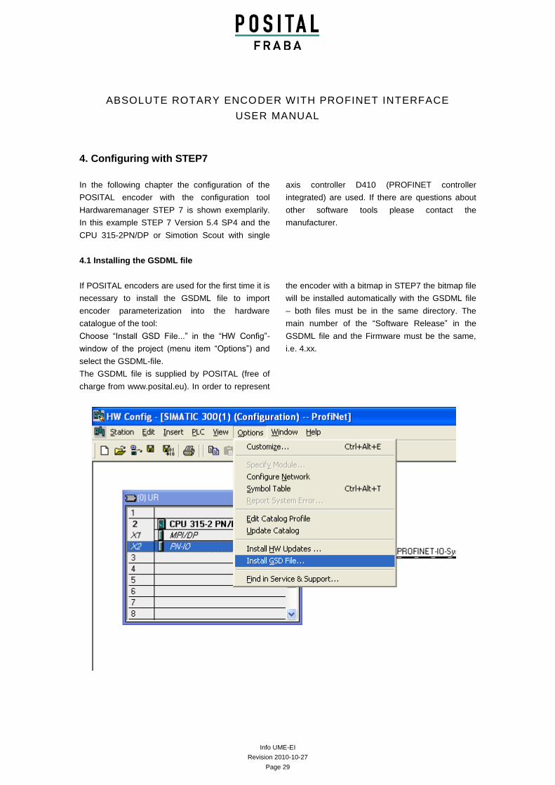
4.1 Installing the GSDML file
If POSITAL encoders are used for the first time it is
necessary to install the GSDML file to import
encoder parameterization into the hardware
catalogue of the tool:
Choose “Install GSD File...” in the “HW Config”-
window of the project (menu item “Options”) and
select the GSDML-file.
The GSDML file is supplied by POSITAL (free of
charge from www.posital.eu). In order to represent
the encoder with a bitmap in STEP7 the bitmap file
will be installed automatically with the GSDML file
– both files must be in the same directory. The
main number of the “Software Release” in the
GSDML file and the Firmware must be the same,
i.e. 4.xx.
Info UME-EI
Revision 2010-10-27
Page 30
ABSOLUTE ROTARY ENCODER WITH PROFINET INTERFACE
USER MANUAL
After the successful installation of the GSDML file
the POSITAL encoder can be found in the
hardware catalog under „PROFINET-IO“ –
„Additional Field Devices“ – „Encoders“ –
„POSITAL OCD“.
(Possibly, you need to update the hardware
catalog by choosing “Options” -> “Update
catalog”).
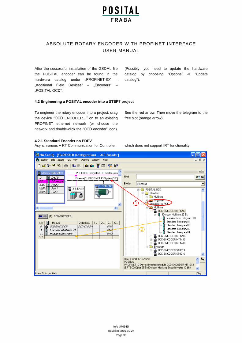
4.2 Engineering a POSITAL encoder into a STEP7 project
To engineer the rotary encoder into a project, drag
the device “OCD ENCODER…” on to an existing
PROFINET ethernet network (or choose the
network and double-click the “OCD encoder” icon).
See the red arrow. Then move the telegram to the
free slot (orange arrow).
4.2.1 Standard Encoder no PDEV
Asynchronous + RT Communication for Controller which does not support IRT functionality.
Info UME-EI
Revision 2010-10-27
Page 31
ABSOLUTE ROTARY ENCODER WITH PROFINET INTERFACE
USER MANUAL
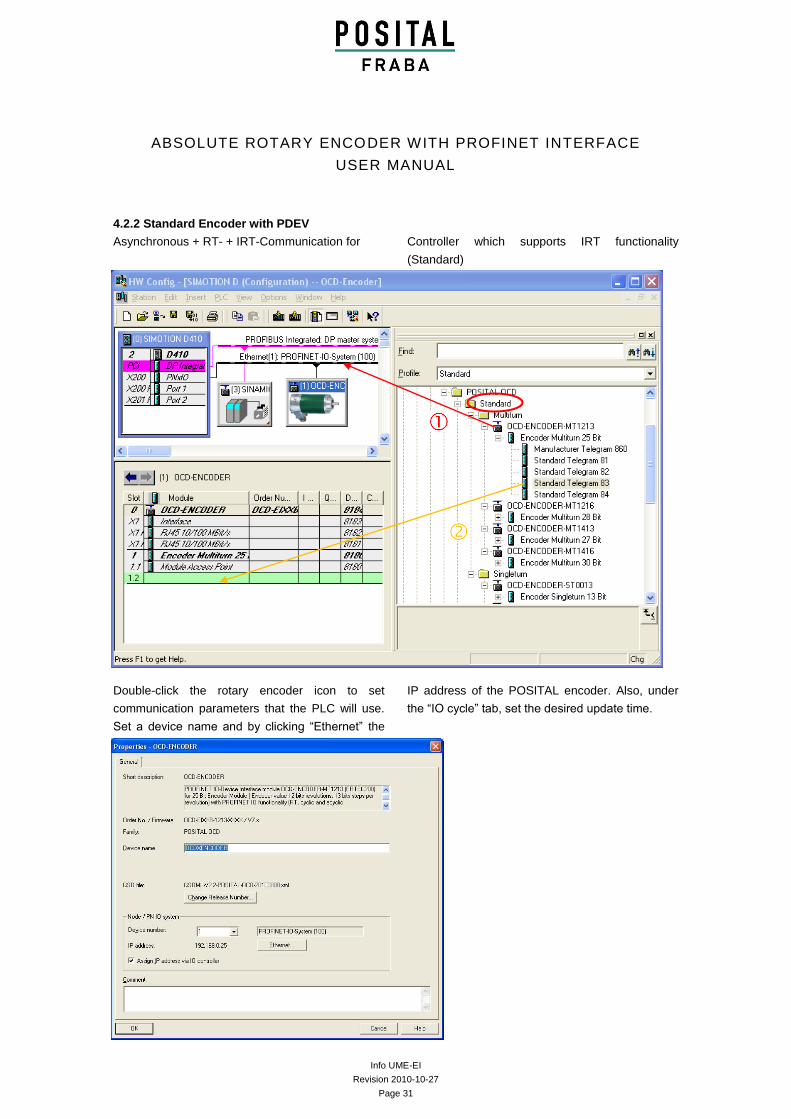
4.2.2 Standard Encoder with PDEV
Asynchronous + RT- + IRT-Communication for Controller which supports IRT functionality
(Standard)
Double-click the rotary encoder icon to set
communication parameters that the PLC will use.
Set a device name and by clicking “Ethernet” the
IP address of the POSITAL encoder. Also, under
the “IO cycle” tab, set the desired update time.
Info UME-EI
Revision 2010-10-27
Page 32
ABSOLUTE ROTARY ENCODER WITH PROFINET INTERFACE
USER MANUAL
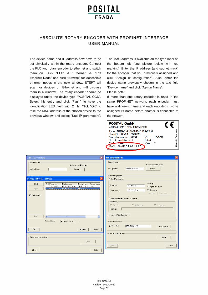
The device name and IP address now have to be
set physically within the rotary encoder. Connect
the PLC and rotary encoder to ethernet and switch
them on. Click “PLC” -> “Ethernet” -> “Edit
Ethernet Node” and click “Browse” for accessible
ethernet nodes in the new window. STEP7 will
scan for devices on Ethernet and will displays
them in a window. The rotary encoder should be
displayed under the device type “POSITAL OCD”.
Select this entry and click “Flash” to have the
identification LED flash with 2 Hz. Click “OK” to
take the MAC address of the chosen device to the
previous window and select “Use IP parameters”.
The MAC address is available on the type label on
the bottom left (see picture below with red
marking). Enter the IP address (and subnet mask)
for the encoder that you previously assigned and
click “Assign IP configuration”. Also, enter the
device name previously chosen in the text field
“Device name” and click “Assign Name”.
Please note:
If more than one rotary encoder is used in the
same PROFINET network, each encoder must
have a different name and each encoder must be
assigned its name before another is connected to
the network.
Info UME-EI
Revision 2010-10-27
Page 33
ABSOLUTE ROTARY ENCODER WITH PROFINET INTERFACE
USER MANUAL
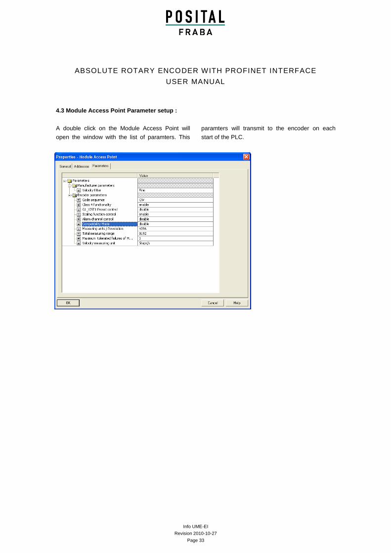
4.3 Module Access Point Parameter setup :
A double click on the Module Access Point will
open the window with the list of paramters. This
paramters will transmit to the encoder on each
start of the PLC.
Info UME-EI
Revision 2010-10-27
Page 34
ABSOLUTE ROTARY ENCODER WITH PROFINET INTERFACE
USER MANUAL
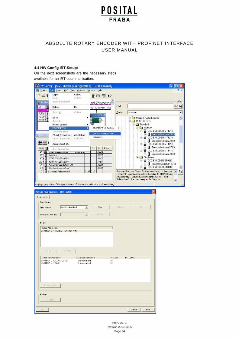
4.4 HW Config IRT-Setup:
On the next screenshots are the necessary steps
available for an IRT coummunication.
Info UME-EI
Revision 2010-10-27
Page 35
ABSOLUTE ROTARY ENCODER WITH PROFINET INTERFACE
USER MANUAL
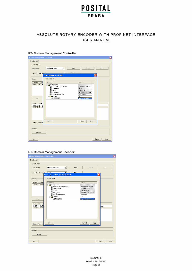
IRT- Domain Management Controller
IRT- Domain Management Encoder:
Info UME-EI
Revision 2010-10-27
Page 36
ABSOLUTE ROTARY ENCODER WITH PROFINET INTERFACE
USER MANUAL
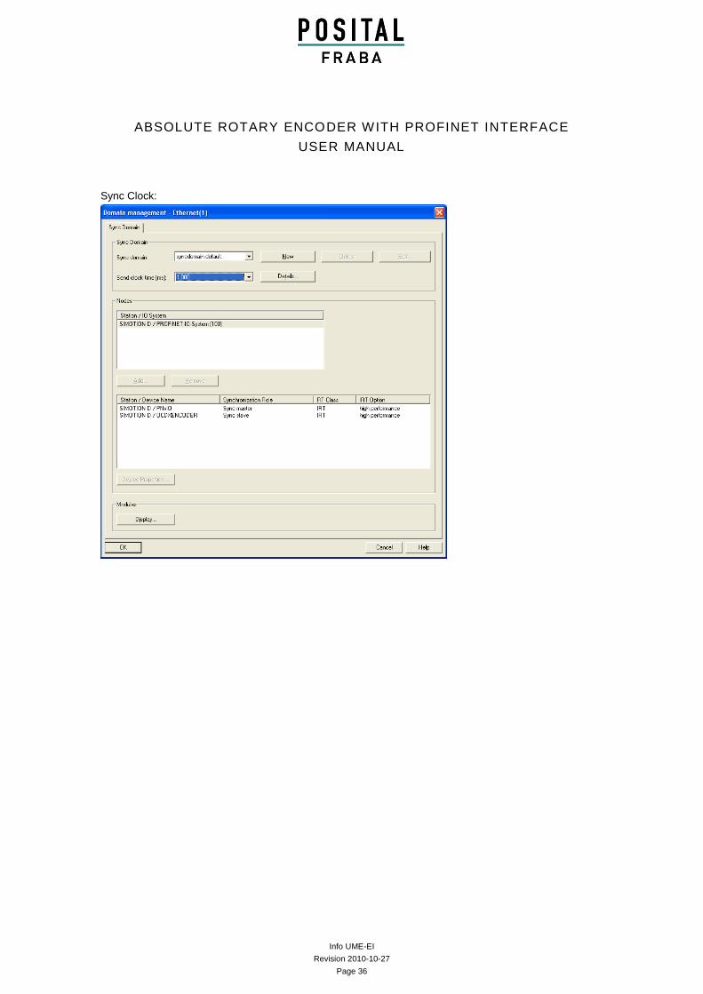
Sync Clock:
Info UME-EI
Revision 2010-10-27
Page 37
ABSOLUTE ROTARY ENCODER WITH PROFINET INTERFACE
USER MANUAL
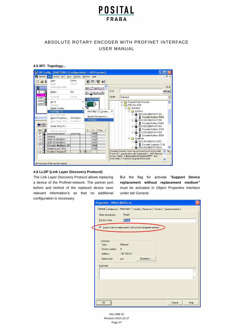
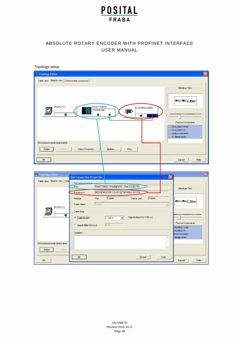
4.5 IRT- Topology...
4.6 LLDP (Link Layer Discovery Protocol)
The Link Layer Discovery Protocol allows replacing
a device of the Profinet-network. The partner port
before and behind of the replaced device save
relevant information’s so that no additional
configuration is necessary.
But the flag for activate “Support Device
replacement without replacement medium”
must be activated in Object Properties Interface
under tab General.
Info UME-EI
Revision 2010-10-27
Page 38
ABSOLUTE ROTARY ENCODER WITH PROFINET INTERFACE
USER MANUAL
Topology-setup:
Info UME-EI
Revision 2010-10-27
Page 39
ABSOLUTE ROTARY ENCODER WITH PROFINET INTERFACE
USER MANUAL
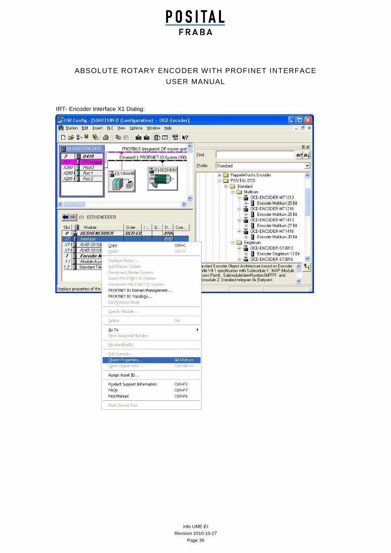
IRT- Encoder Interface X1 Dialog:
Info UME-EI
Revision 2010-10-27
Page 40
ABSOLUTE ROTARY ENCODER WITH PROFINET INTERFACE
USER MANUAL
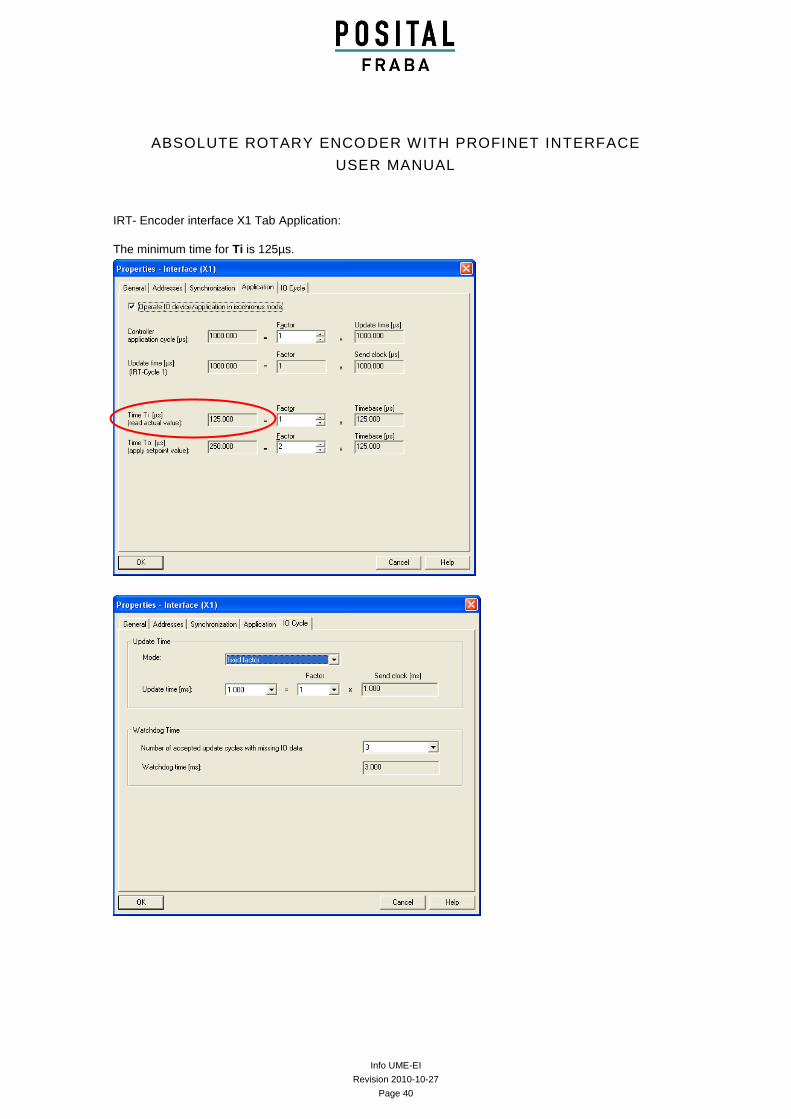
IRT- Encoder interface X1 Tab Application:
The minimum time for Ti is 125µs.
Info UME-EI
Revision 2010-10-27
Page 41
ABSOLUTE ROTARY ENCODER WITH PROFINET INTERFACE
USER MANUAL
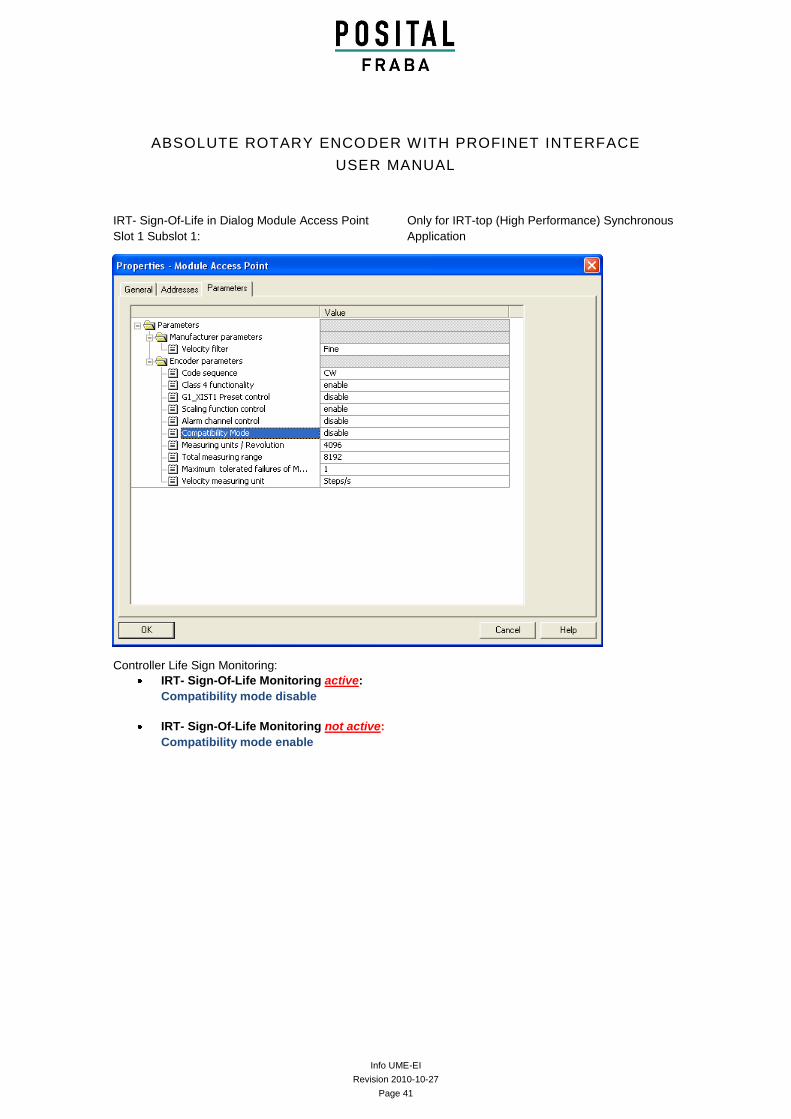
IRT- Sign-Of-Life in Dialog Module Access Point
Slot 1 Subslot 1:
Only for IRT-top (High Performance) Synchronous
Application
Controller Life Sign Monitoring:
IRT- Sign-Of-Life Monitoring active:
Compatibility mode disable
IRT- Sign-Of-Life Monitoring not active:
Compatibility mode enable
Info UME-EI
Revision 2010-10-27
Page 42
ABSOLUTE ROTARY ENCODER WITH PROFINET INTERFACE
USER MANUAL
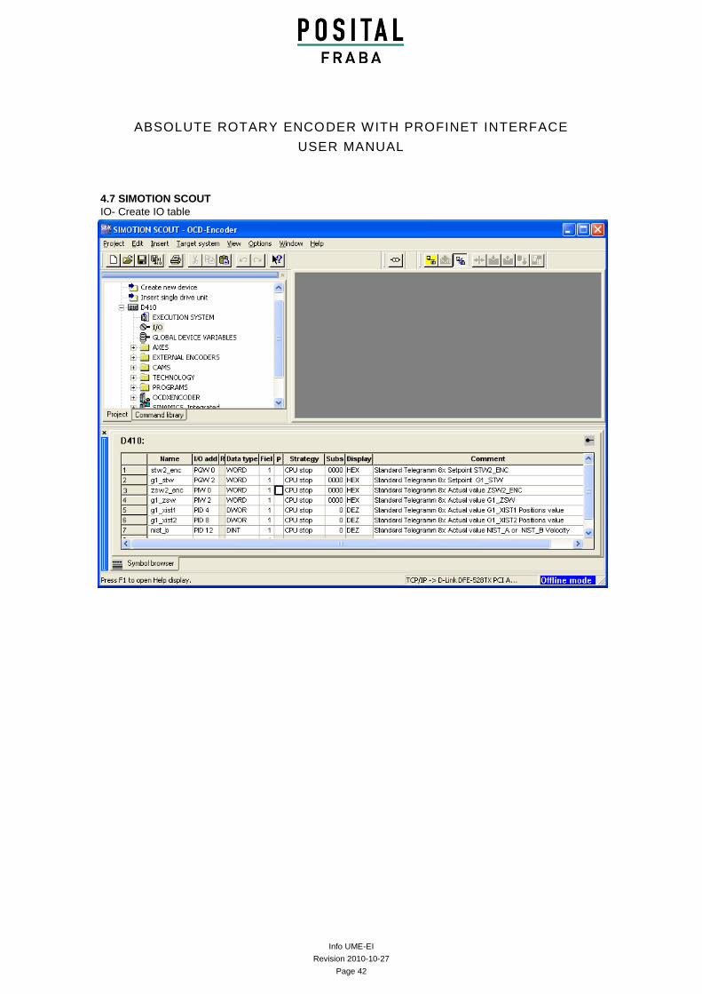
4.7 SIMOTION SCOUT
IO- Create IO table
Info UME-EI
Revision 2010-10-27
Page 43
ABSOLUTE ROTARY ENCODER WITH PROFINET INTERFACE
USER MANUAL
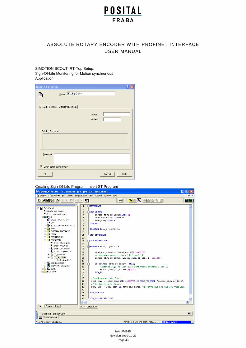
SIMOTION SCOUT IRT-Top Setup:
Sign-Of-Life Monitoring for Motion synchronous
Application
Creating Sign-Of-Life Program: Insert ST Program
Info UME-EI
Revision 2010-10-27
Page 44
ABSOLUTE ROTARY ENCODER WITH PROFINET INTERFACE
USER MANUAL
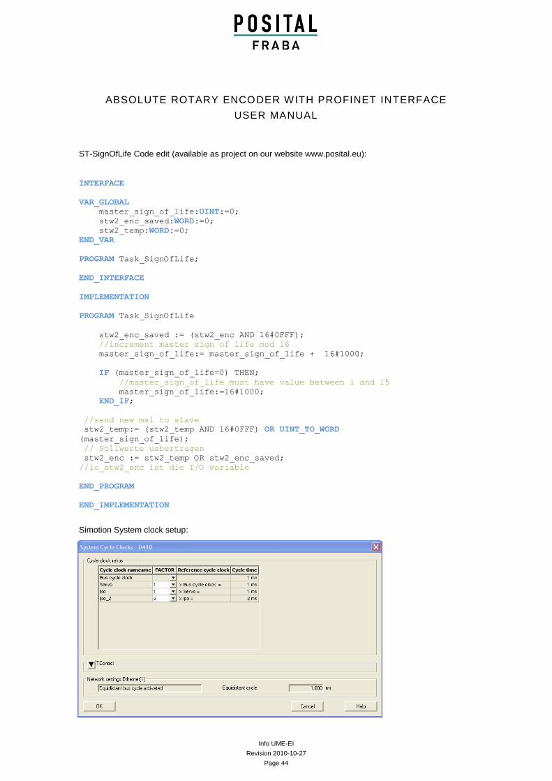
ST-SignOfLife Code edit (available as project on our website www.posital.eu):
INTERFACE
VAR_GLOBAL
master_sign_of_life:UINT:=0;
stw2_enc_saved:WORD:=0;
stw2_temp:WORD:=0;
END_VAR
PROGRAM Task_SignOfLife;
END_INTERFACE
IMPLEMENTATION
PROGRAM Task_SignOfLife
stw2_enc_saved := (stw2_enc AND 16#0FFF);
//increment master sign of life mod 16
master_sign_of_life:= master_sign_of_life + 16#1000;
IF (master_sign_of_life=0) THEN;
//master_sign_of_life must have value between 1 and 15
master_sign_of_life:=16#1000;
END_IF;
//send new msl to slave
stw2_temp:= (stw2_temp AND 16#0FFF) OR UINT_TO_WORD
(master_sign_of_life);
// Sollwerte uebertragen
stw2_enc := stw2_temp OR stw2_enc_saved;
//io_stw2_enc ist die I/O variable
END_PROGRAM
END_IMPLEMENTATION
Simotion System clock setup:
Info UME-EI
Revision 2010-10-27
Page 45
ABSOLUTE ROTARY ENCODER WITH PROFINET INTERFACE
USER MANUAL
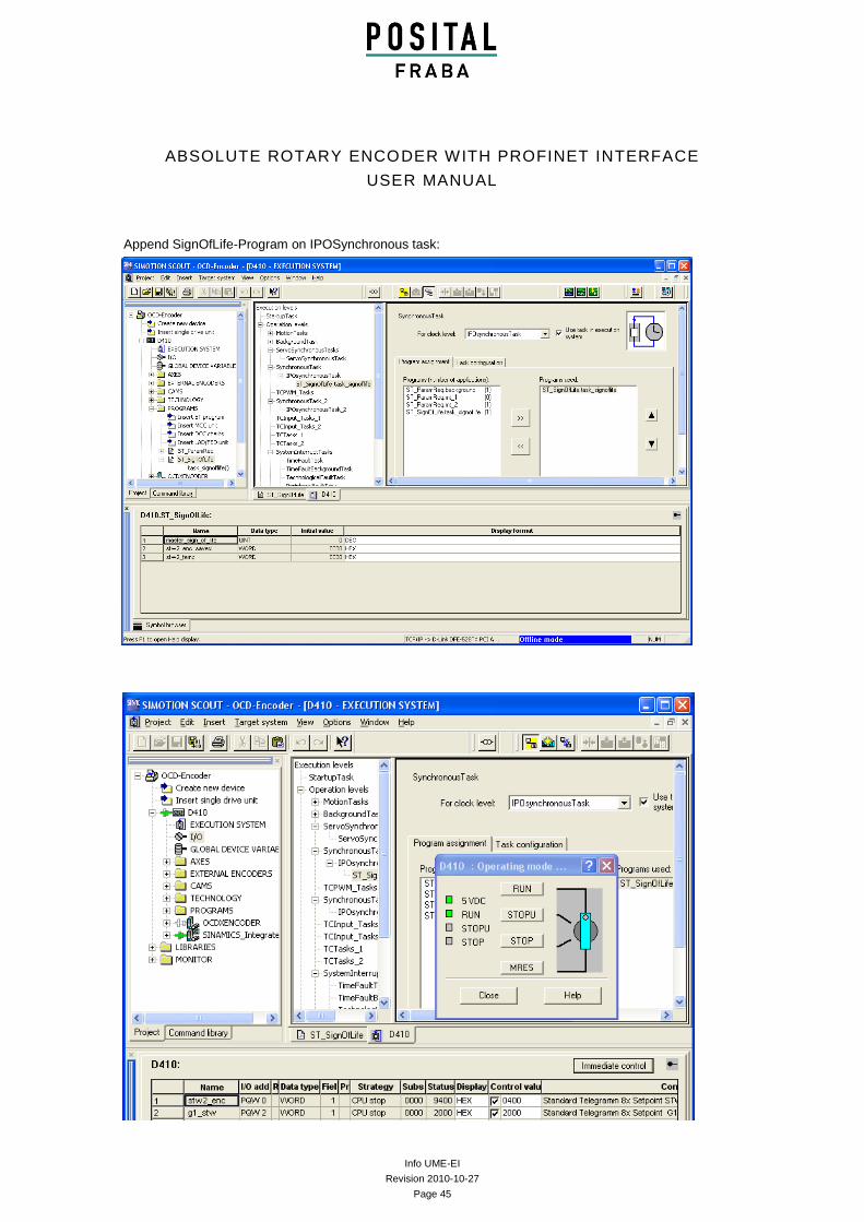
Append SignOfLife-Program on IPOSynchronous task:
Info UME-EI
Revision 2010-10-27
Page 46
ABSOLUTE ROTARY ENCODER WITH PROFINET INTERFACE
USER MANUAL
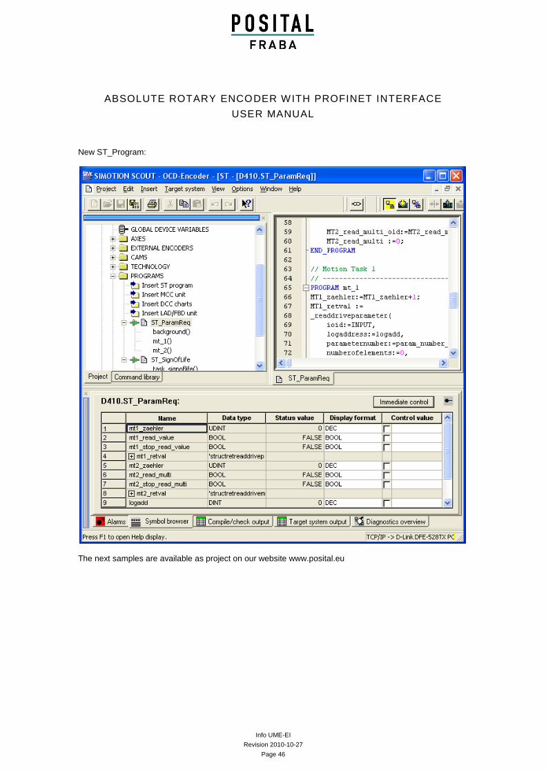
New ST_Program:
The next samples are available as project on our website www.posital.eu
Info UME-EI
Revision 2010-10-27
Page 47
ABSOLUTE ROTARY ENCODER WITH PROFINET INTERFACE
USER MANUAL
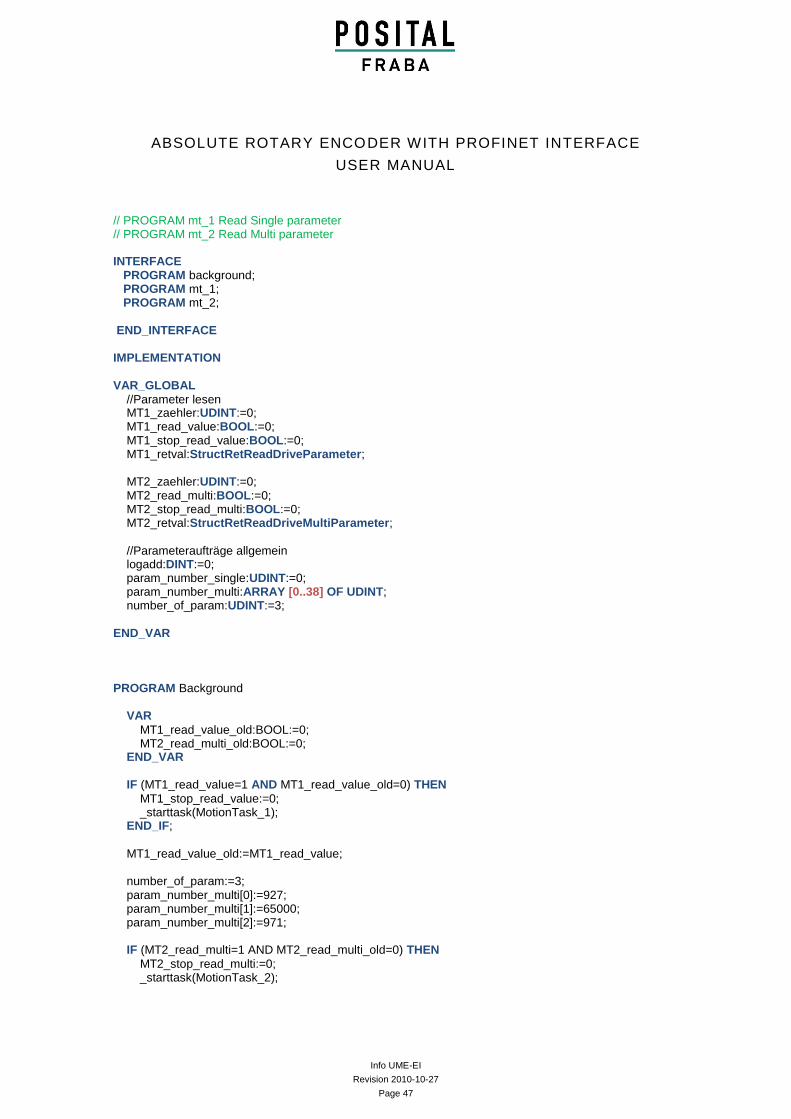
// PROGRAM mt_1 Read Single parameter // PROGRAM mt_2 Read Multi parameter INTERFACE PROGRAM background; PROGRAM mt_1; PROGRAM mt_2;
END_INTERFACE
IMPLEMENTATION
VAR_GLOBAL
//Parameter lesen MT1_zaehler:UDINT:=0; MT1_read_value:BOOL:=0; MT1_stop_read_value:BOOL:=0; MT1_retval:StructRetReadDriveParameter;
MT2_zaehler:UDINT:=0; MT2_read_multi:BOOL:=0; MT2_stop_read_multi:BOOL:=0; MT2_retval:StructRetReadDriveMultiParameter;
//Parameteraufträge allgemein logadd:DINT:=0; param_number_single:UDINT:=0; param_number_multi:ARRAY [0..38] OF UDINT; number_of_param:UDINT:=3;
END_VAR
PROGRAM Background
VAR
MT1_read_value_old:BOOL:=0; MT2_read_multi_old:BOOL:=0; END_VAR
IF (MT1_read_value=1 AND MT1_read_value_old=0) THEN
MT1_stop_read_value:=0; _starttask(MotionTask_1); END_IF;
MT1_read_value_old:=MT1_read_value; number_of_param:=3; param_number_multi[0]:=927; param_number_multi[1]:=65000; param_number_multi[2]:=971; IF (MT2_read_multi=1 AND MT2_read_multi_old=0) THEN
MT2_stop_read_multi:=0; _starttask(MotionTask_2);
Info UME-EI
Revision 2010-10-27
Page 48
ABSOLUTE ROTARY ENCODER WITH PROFINET INTERFACE
USER MANUAL
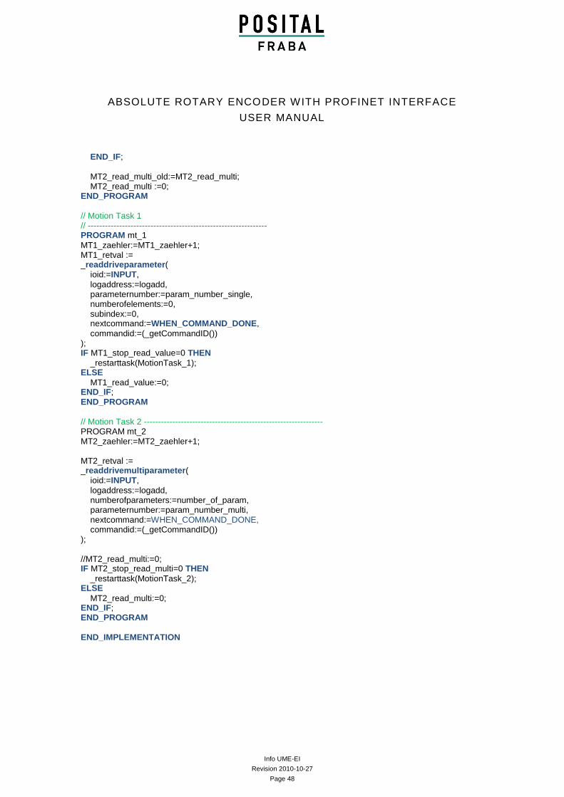
END_IF;
MT2_read_multi_old:=MT2_read_multi; MT2_read_multi :=0; END_PROGRAM
// Motion Task 1 // --------------------------------------------------------------- PROGRAM mt_1
MT1_zaehler:=MT1_zaehler+1; MT1_retval := _readdriveparameter( ioid:=INPUT,
logaddress:=logadd, parameternumber:=param_number_single, numberofelements:=0, subindex:=0, nextcommand:=WHEN_COMMAND_DONE,
commandid:=(_getCommandID()) ); IF MT1_stop_read_value=0 THEN
_restarttask(MotionTask_1); ELSE
MT1_read_value:=0; END_IF; END_PROGRAM
// Motion Task 2 --------------------------------------------------------------- PROGRAM mt_2 MT2_zaehler:=MT2_zaehler+1; MT2_retval := _readdrivemultiparameter( ioid:=INPUT,
logaddress:=logadd, numberofparameters:=number_of_param, parameternumber:=param_number_multi, nextcommand:=WHEN_COMMAND_DONE, commandid:=(_getCommandID()) ); //MT2_read_multi:=0; IF MT2_stop_read_multi=0 THEN
_restarttask(MotionTask_2); ELSE
MT2_read_multi:=0; END_IF; END_PROGRAM
END_IMPLEMENTATION
Info UME-EI
Revision 2010-10-27
Page 49
ABSOLUTE ROTARY ENCODER WITH PROFINET INTERFACE
USER MANUAL
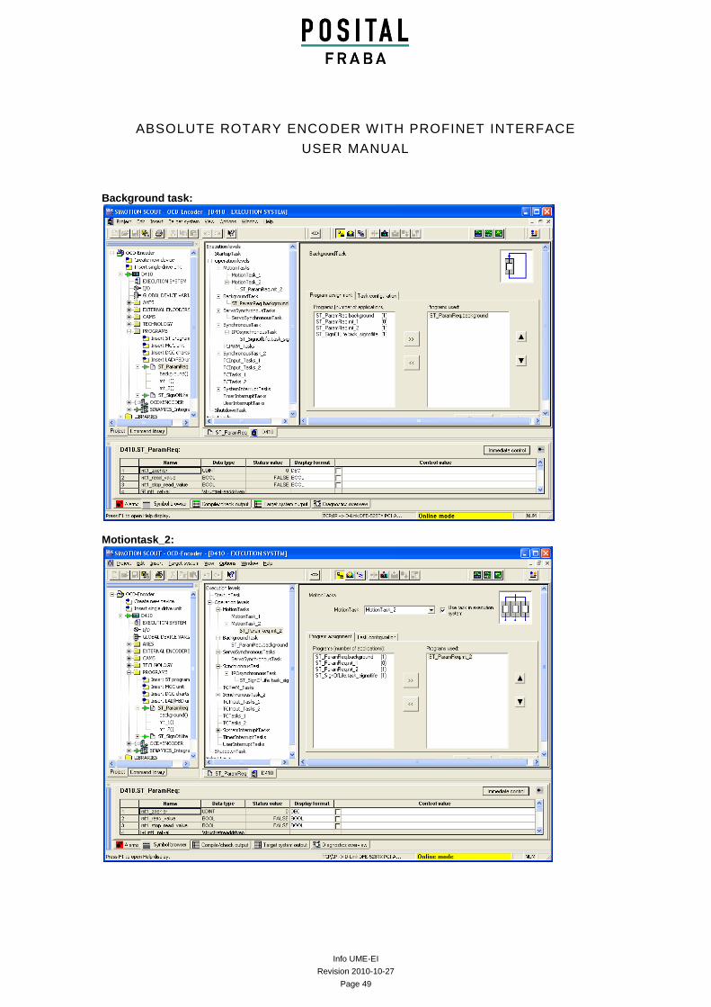
Background task:
Motiontask_2:
Info UME-EI
Revision 2010-10-27
Page 50
ABSOLUTE ROTARY ENCODER WITH PROFINET INTERFACE
USER MANUAL
5 IRT communication
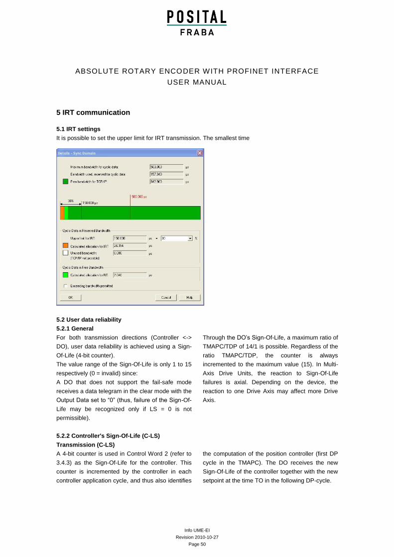
5.1 IRT settings
It is possible to set the upper limit for IRT transmission. The smallest time
5.2 User data reliability
5.2.1 General
For both transmission directions (Controller <->
DO), user data reliability is achieved using a Sign-
Of-Life (4-bit counter).
The value range of the Sign-Of-Life is only 1 to 15
respectively (0 = invalid) since:
A DO that does not support the fail-safe mode
receives a data telegram in the clear mode with the
Output Data set to “0” (thus, failure of the Sign-Of-
Life may be recognized only if LS = 0 is not
permissible).
Through the DO’s Sign-Of-Life, a maximum ratio of
TMAPC/TDP of 14/1 is possible. Regardless of the
ratio TMAPC/TDP, the counter is always
incremented to the maximum value (15). In Multi-
Axis Drive Units, the reaction to Sign-Of-Life
failures is axial. Depending on the device, the
reaction to one Drive Axis may affect more Drive
Axis.
5.2.2 Controller's Sign-Of-Life (C-LS)
Transmission (C-LS)
A 4-bit counter is used in Control Word 2 (refer to
3.4.3) as the Sign-Of-Life for the controller. This
counter is incremented by the controller in each
controller application cycle, and thus also identifies
the computation of the position controller (first DP
cycle in the TMAPC). The DO receives the new
Sign-Of-Life of the controller together with the new
setpoint at the time TO in the following DP-cycle.
Info UME-EI
Revision 2010-10-27
Page 51
ABSOLUTE ROTARY ENCODER WITH PROFINET INTERFACE
USER MANUAL
Synchronization (C-LS)
The Controller application starts the Controller-LS
with an arbitrary value between 1 and 15, at the
earliest when changing from Preparation ->
Synchronization.
Monitoring (C-LS)
If, in a Controller application cycle, the DO
application does not recognize a correct count (i.e.
a positive or a negative deviation is recognized), it
initially processes with the old telegram data from
the last valid controller telegram. For setpoint
generation, a device-specific failure strategy may
be used.
If the DO application does not recognize the
expected numerical value after a parameterized
number of controller application cycles (TMLS = n
× TMAPC; n may be selected via profile parameter
925; also refer to chapter 5.1.4), the affected Drive
Axis messages a fault. After fault
acknowledgement, the DO application then
attempts to automatically resynchronize itself to the
Sign-Of-Life of the controller application.
Depending on the particular application, a new
start may be required.
If the Sign-Of-Life fails, it may be for the following
reasons:
Sign-Of-Life failure
Failure of the controller application level
(with DP transmission still operational)
PLL failure
The DP cycle TDP has been exceeded
(through telegram repetition)
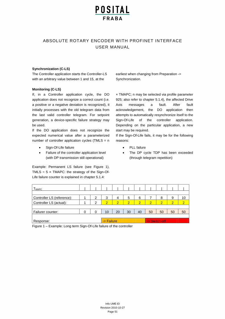
Example: Permanent LS failure (see Figure 1),
TMLS = 5 × TMAPC: the strategy of the Sign-Of-
Life failure counter is explained in chapter 5.1.4:
TMAPC | | | | | | | | | |
Controller LS (reference): 1 2 3 4 5 6 7 8 9 10
Controller LS (actual): 1 2 2 2 2 2 2 2 2 2
Failurer counter: 0 0 10 20 30 40 50 50 50 50
Response: -> Failure -> Switch-off
Figure 1 – Example: Long term Sign-Of-Life failure of the controller
Info UME-EI
Revision 2010-10-27
Page 52
ABSOLUTE ROTARY ENCODER WITH PROFINET INTERFACE
USER MANUAL
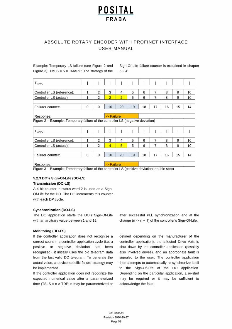
Example: Temporary LS failure (see Figure 2 and
Figure 3), TMLS = 5 × TMAPC: The strategy of the
Sign-Of-Life failure counter is explained in chapter
5.2.4:
TMAPC | | | | | | | | | |
Controller LS (reference): 1 2 3 4 5 6 7 8 9 10
Controller LS (actual): 1 2 2 2 5 6 7 8 9 10
Failurer counter: 0 0 10 20 19 18 17 16 15 14
Response: -> Failure
Figure 2 – Example: Temporary failure of the controller LS (negative deviation)
TMAPC | | | | | | | | | |
Controller LS (reference): 1 2 3 4 5 6 7 8 9 10
Controller LS (actual): 1 2 4 5 5 6 7 8 9 10
Failurer counter: 0 0 10 20 19 18 17 16 15 14
Response: -> Failure
Figure 3 – Example: Temporary failure of the controller LS (positive deviation; double step)
5.2.3 DO’s Sign-Of-Life (DO-LS)
Transmission (DO-LS)
A 4-bit counter in status word 2 is used as a Sign-
Of-Life for the DO. The DO increments this counter
with each DP cycle.
Synchronization (DO-LS)
The DO application starts the DO’s Sign-Of-Life
with an arbitrary value between 1 and 15:
after successful PLL synchronization and at the
change (n -> n + 1) of the controller’s Sign-Of-Life.
Monitoring (DO-LS)
If the controller application does not recognize a
correct count in a controller application cycle (i.e. a
positive or negative deviation has been
recognized), it initially uses the old telegram data
from the last valid DO telegram. To generate the
actual value, a device-specific failure strategy may
be implemented.
If the controller application does not recognize the
expected numerical value after a parameterized
time (TSLS = n × TDP; n may be parameterized or
defined depending on the manufacturer of the
controller application), the affected Drive Axis is
shut down by the controller application (possibly
also involved drives), and an appropriate fault is
signaled to the user. The controller application
then attempts to automatically re-synchronize itself
to the Sign-Of-Life of the DO application.
Depending on the particular application, a re-start
may be required or it may be sufficient to
acknowledge the fault.
Info UME-EI
Revision 2010-10-27
Page 53
ABSOLUTE ROTARY ENCODER WITH PROFINET INTERFACE
USER MANUAL
Example reasons for the Sign-Of-Life to fail may be:
Sign-Of-Life failure
Failure of the DO application level (while
DP transmission is still functioning)
PLL failure
DO failure in the sense of DP (DO does
not respond although telegram was
repeated)
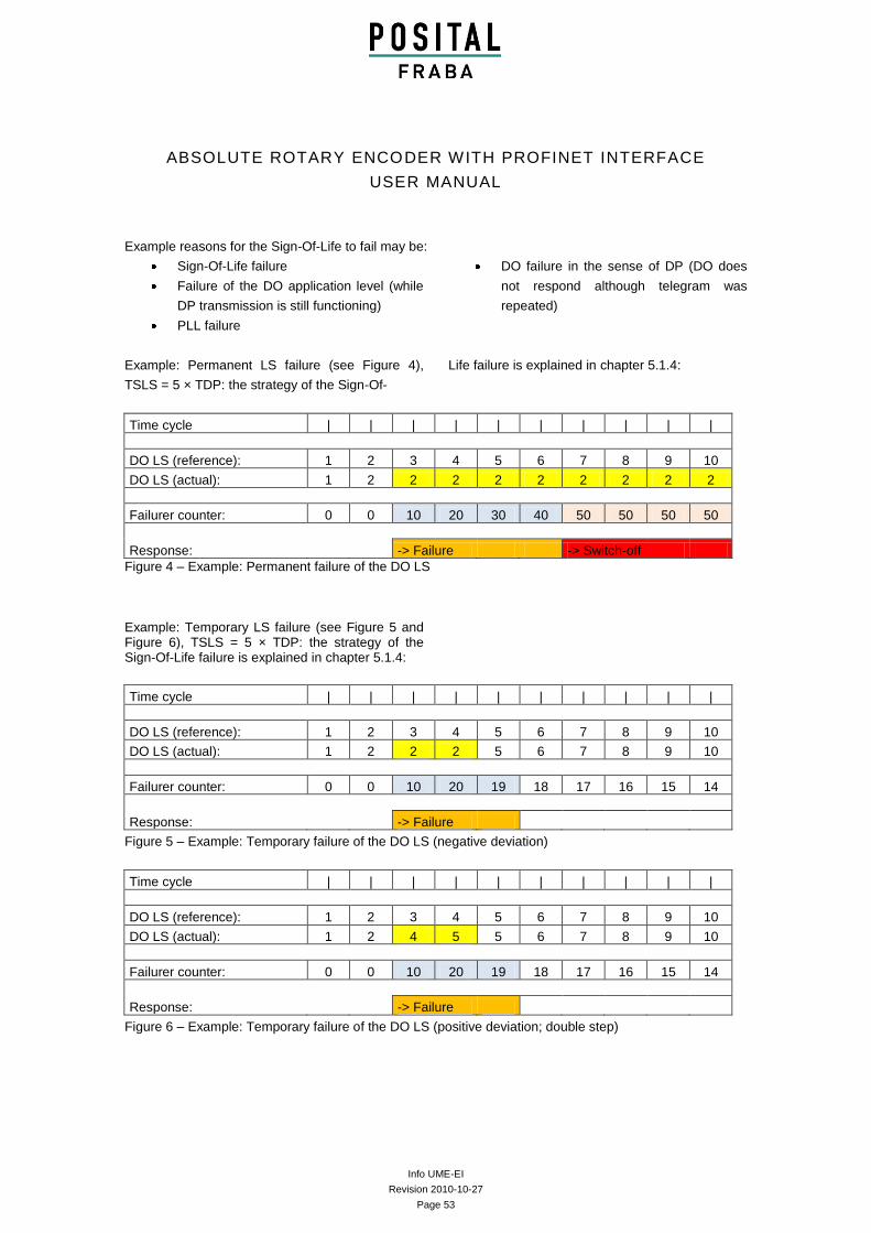
Example: Permanent LS failure (see Figure 4),
TSLS = 5 × TDP: the strategy of the Sign-Of-
Life failure is explained in chapter 5.1.4:
Time cycle | | | | | | | | | |
DO LS (reference): 1 2 3 4 5 6 7 8 9 10
DO LS (actual): 1 2 2 2 2 2 2 2 2 2
Failurer counter: 0 0 10 20 30 40 50 50 50 50
Response: -> Failure -> Switch-off
Figure 4 – Example: Permanent failure of the DO LS
Example: Temporary LS failure (see Figure 5 and Figure 6), TSLS = 5 × TDP: the strategy of the Sign-Of-Life failure is explained in chapter 5.1.4:
Time cycle | | | | | | | | | |
DO LS (reference): 1 2 3 4 5 6 7 8 9 10
DO LS (actual): 1 2 2 2 5 6 7 8 9 10
Failurer counter: 0 0 10 20 19 18 17 16 15 14
Response: -> Failure
Figure 5 – Example: Temporary failure of the DO LS (negative deviation)
Time cycle | | | | | | | | | |
DO LS (reference): 1 2 3 4 5 6 7 8 9 10
DO LS (actual): 1 2 4 5 5 6 7 8 9 10
Failurer counter: 0 0 10 20 19 18 17 16 15 14
Response: -> Failure
Figure 6 – Example: Temporary failure of the DO LS (positive deviation; double step)
Info UME-EI
Revision 2010-10-27
Page 54
ABSOLUTE ROTARY ENCODER WITH PROFINET INTERFACE
USER MANUAL
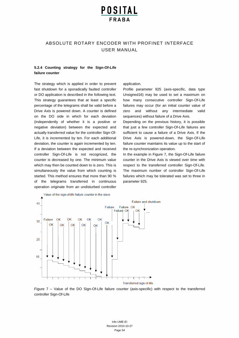
5.2.4 Counting strategy for the Sign-Of-Life
failure counter
The strategy which is applied in order to prevent
fast shutdown for a sporadically faulted controller
or DO application is described in the following text.
This strategy guarantees that at least a specific
percentage of the telegrams shall be valid before a
Drive Axis is powered down. A counter is defined
on the DO side in which for each deviation
(independently of whether it is a positive or
negative deviation) between the expected and
actually transferred value for the controller Sign-Of-
Life, it is incremented by ten. For each additional
deviation, the counter is again incremented by ten.
If a deviation between the expected and received
controller Sign-Of-Life is not recognized, the
counter is decreased by one. The minimum value
which may then be counted down to is zero. This is
simultaneously the value from which counting is
started. This method ensures that more than 90 %
of the telegrams transferred in continuous
operation originate from an undisturbed controller
application.
Profile parameter 925 (axis-specific, data type
Unsigned16) may be used to set a maximum on
how many consecutive controller Sign-Of-Life
failures may occur (for an initial counter value of
zero and without any intermediate valid
sequences) without failure of a Drive Axis.
Depending on the previous history, it is possible
that just a few controller Sign-Of-Life failures are
sufficient to cause a failure of a Drive Axis. If the
Drive Axis is powered-down, the Sign-Of-Life
failure counter maintains its value up to the start of
the re-synchronization operation.
In the example in Figure 7, the Sign-Of-Life failure
counter in the Drive Axis is viewed over time with
respect to the transferred controller Sign-Of-Life.
The maximum number of controller Sign-Of-Life
failures which may be tolerated was set to three in
parameter 925.
Figure 7 – Value of the DO Sign-Of-Life failure counter (axis-specific) with respect to the transferred
controller Sign-Of-Life
Info UME-EI
Revision 2010-10-27
Page 55
ABSOLUTE ROTARY ENCODER WITH PROFINET INTERFACE
USER MANUAL
The same strategy is recommended when
monitoring the DO Sign-Of-Life in the controller.
However, it has not been defined with which
parameter the maximum number of tolerable DO
Sign-Of-Life character failures may be
parameterized.
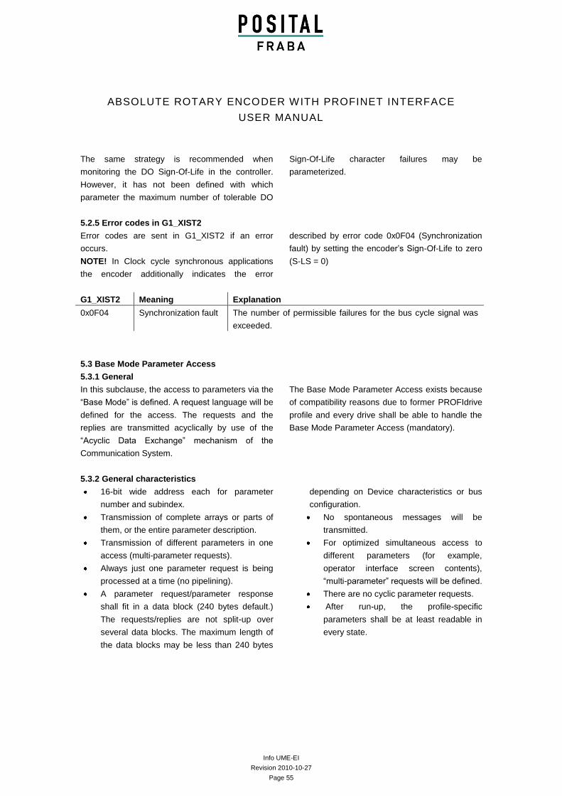
5.2.5 Error codes in G1_XIST2
Error codes are sent in G1_XIST2 if an error
occurs.
NOTE! In Clock cycle synchronous applications
the encoder additionally indicates the error
described by error code 0x0F04 (Synchronization
fault) by setting the encoder’s Sign-Of-Life to zero
(S-LS = 0)
G1_XIST2 Meaning Explanation
0x0F04 Synchronization fault The number of permissible failures for the bus cycle signal was
exceeded.
5.3 Base Mode Parameter Access
5.3.1 General
In this subclause, the access to parameters via the
“Base Mode” is defined. A request language will be
defined for the access. The requests and the
replies are transmitted acyclically by use of the
“Acyclic Data Exchange” mechanism of the
Communication System.
The Base Mode Parameter Access exists because
of compatibility reasons due to former PROFIdrive
profile and every drive shall be able to handle the
Base Mode Parameter Access (mandatory).
5.3.2 General characteristics
16-bit wide address each for parameter
number and subindex.
Transmission of complete arrays or parts of
them, or the entire parameter description.
Transmission of different parameters in one
access (multi-parameter requests).
Always just one parameter request is being
processed at a time (no pipelining).
A parameter request/parameter response
shall fit in a data block (240 bytes default.)
The requests/replies are not split-up over
several data blocks. The maximum length of
the data blocks may be less than 240 bytes
depending on Device characteristics or bus
configuration.
No spontaneous messages will be
transmitted.
For optimized simultaneous access to
different parameters (for example,
operator interface screen contents),
“multi-parameter” requests will be defined.
There are no cyclic parameter requests.
After run-up, the profile-specific
parameters shall be at least readable in
every state.
Info UME-EI
Revision 2010-10-27
Page 56
ABSOLUTE ROTARY ENCODER WITH PROFINET INTERFACE
USER MANUAL
5.3.3 DO addressing modes
The Base Mode Parameter Access is defined with
two different DO address modes according to the
following definition:
Base Mode Parameter Access – Local: In this
address mode, only the local parameters of
the DO are accessible, to which the CO,
where the parameter access point is
attached, is related. Access of all global
parameters is also possible. The DO-ID in the
parameter request header is of no
significance.
Base Mode Parameter Access – Global: In
this address mode, all parameters of the
Drive Unit are accessible, to which the CO,
where the parameter access point is
attached, is related. The DO-ID in the
parameter request is used for accessing of
local parameters inside the Drive Unit. For
access of global parameters, the DO-ID 0
may also be used. This address mode serves
for compatibility reasons (PROFIBUS) and
should not be used by new PROFINET IO
controller and Supervisor application
processes.
5.3.4 Parameter requests and parameter responses
A parameter request consists of three segments:
Request header
ID for the request and number of parameters which
are accessed. Multi-Axis and Modular drives,
Addressing of one DO.
Parameter address
Addressing of a parameter. If several parameters
are accessed, there are correspondingly many
parameter addresses. The parameter address
appears only in the request, not in the response.
Parameter value
Per addressed parameter, there is a segment for
the parameter values. Depending on the request
ID, parameter values appear only in either the
request or in the reply.
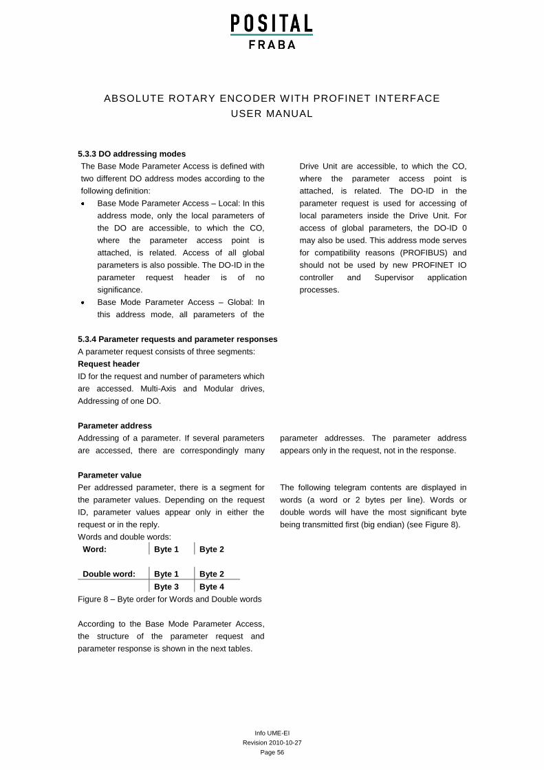
Words and double words:
The following telegram contents are displayed in
words (a word or 2 bytes per line). Words or
double words will have the most significant byte
being transmitted first (big endian) (see Figure 8).
Word: Byte 1 Byte 2
Double word: Byte 1 Byte 2
Byte 3 Byte 4
Figure 8 – Byte order for Words and Double words
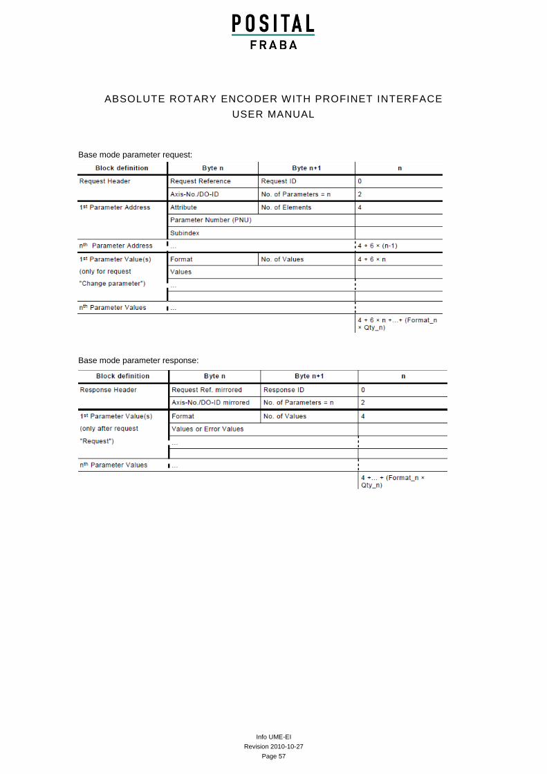
According to the Base Mode Parameter Access,
the structure of the parameter request and
parameter response is shown in the next tables.
Info UME-EI
Revision 2010-10-27
Page 57
ABSOLUTE ROTARY ENCODER WITH PROFINET INTERFACE
USER MANUAL
Base mode parameter request:
Base mode parameter response:
Meaning of the fields:
Info UME-EI
Revision 2010-10-27
Page 58
ABSOLUTE ROTARY ENCODER WITH PROFINET INTERFACE
USER MANUAL
Request Header
Request Reference Unique identification of
the request/response pair for the master. The
master changes the request reference with
each new request (for example, modulo 255).
The slave mirrors the request reference in the
response.
Request ID two IDs are defined:
– Request parameter
– Change parameter
A parameter change may be stored either in
volatile or non-volatile RAM according to the
device. A changed parameter that is stored in
volatile RAM may first be stored in ROM with
parameter P971. The differentiation
Value/Description/Text is added to the
address as an attribute. The differentiation
Word/Double Word is added to the parameter
values as a format. For the differentiation
Single/Array Parameter, refer to “No. of
Elements” in the parameter address.
Response ID
Mirroring of the request ID with supplement
information whether the request was
executed positively or negatively.
– Request parameter positive
– Request parameter negative (it was not
possible to execute the request, entirely or
partially)
– Change parameter positive
– Change parameter negative (it was not
possible to execute the request, entirely or
partially)
If the response is negative, error numbers are
entered per partial response instead of
values.
Axis-No./DO-ID For Base Mode Parameter
Access – Local: irrelevant; In the parameter
response, the DOID out of the request is
mirrored.
For Base Mode Parameter Access – Global:
DO addressing information used for Multi-
Axis or Modular drives. This enables various
axes/DOs to be able to be accessed each
with a dedicated parameter number space in
the drive via the same PAP.
No. of Parameters
In the case of multi-parameter requests,
specifying the number of the following
Parameter
Address and/or Parameter Value areas. For
single requests the No. of parameters = 1.
Default value range 1 to 39. The value range
may be reduced or extended, which shall be
indicated by P974.
Notice, that for a multi-parameter request the
PROFIdrive Drive Unit shall arrange the
parameter value areas in the response
message in the same order as in the
corresponding multi-parameter request
message.
Info UME-EI
Revision 2010-10-27
Page 59
ABSOLUTE ROTARY ENCODER WITH PROFINET INTERFACE
USER MANUAL
Parameter Address
Attribute
Type of object which is being accessed.
Value range:
– Value
– Description
– Text
Number of Elements
Number of array elements that are accessed
or length of string which is accessed.
Default value range 0, 1 to 234. The value
range may be reduced or extended which
shall be indicated by P974.
Special Case Number of Elements = 0:
If values are accessed: recommended for non-
indexed parameters.
Parameter Number
Addresses the parameter that is being
accessed. Value range: 1 to 65535.
Subindex
Addresses the first array element of the
parameter or the beginning of a string access
or the text array, or the description element
that is being accessed. Value range: 0 to 65
535.
Parameter Value
Format
Format and number specify the location in the
telegram to which subsequent values are
assigned.
Value range:
– Zero (without values as positive partial
response to a change request)
– Data type
– Error (as negative partial response)
– Instead of a data type, the following are
possible:
– Byte (for description and texts)
– Word
– Double word
Number of Values
Number of the following values or number of
the following data type elements (number of
octets in case of OctetString). In case of write
request of OctetString, the correct length
shall be supplied otherwise the drive shall
responds with error 0x18, “number of values
are not consistent” (see Table 32).
Values
The values of the parameter
If the values consist of an odd number of
bytes, a zero byte is appended in order to
secure the word structure of the telegrams.
In the case of a positive partial response,
the parameter value contains the following:
– Format = (Data Type or Byte, Word,
Double Word)
– Number of values
– the values
In the case of a negative partial response,
the parameter value contains the following:
– Format = error
– No. of values = 1
– Value = error value = error number
In the case of a negative response, the
parameter value may contain the following:
– Format = error
– No. of values = 2
– Value 1 = Error Value 1: error number
– Value 2 = Error Value 2: subindex of the
first array element where the error occurs
– (Purpose: after a faulty write access to an
array, not all values shall be repeated)
In the case of a positive partial response
without values, the parameter value
contains the following:
– Format = zero
– Number of values = 0
– (no values)
Info UME-EI
Revision 2010-10-27
Page 60
ABSOLUTE ROTARY ENCODER WITH PROFINET INTERFACE
USER MANUAL
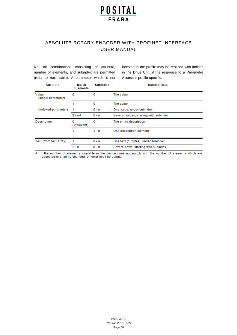
Not all combinations consisting of attribute,
number of elements, and subindex are permitted
(refer to next table). A parameter which is not
indexed in the profile may be realized with indices
in the Drive Unit, if the response to a Parameter
Access is profile-specific.
Info UME-EI
Revision 2010-10-27
Page 61
ABSOLUTE ROTARY ENCODER WITH PROFINET INTERFACE
USER MANUAL
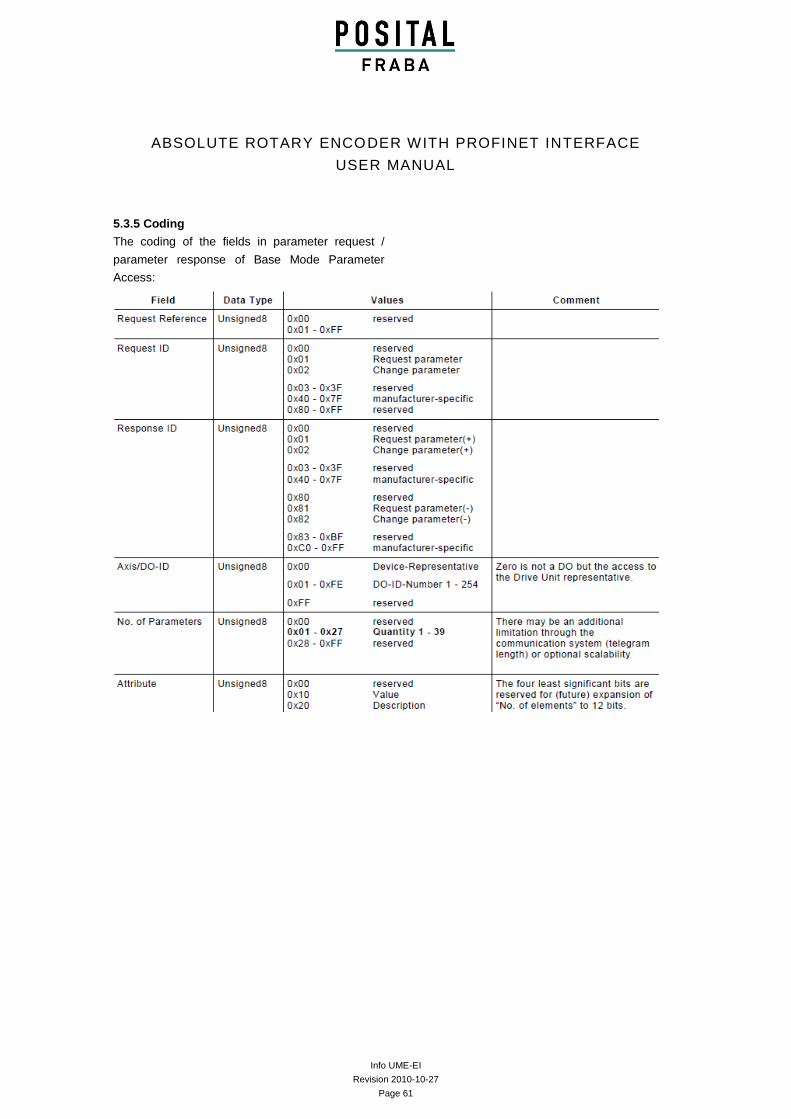
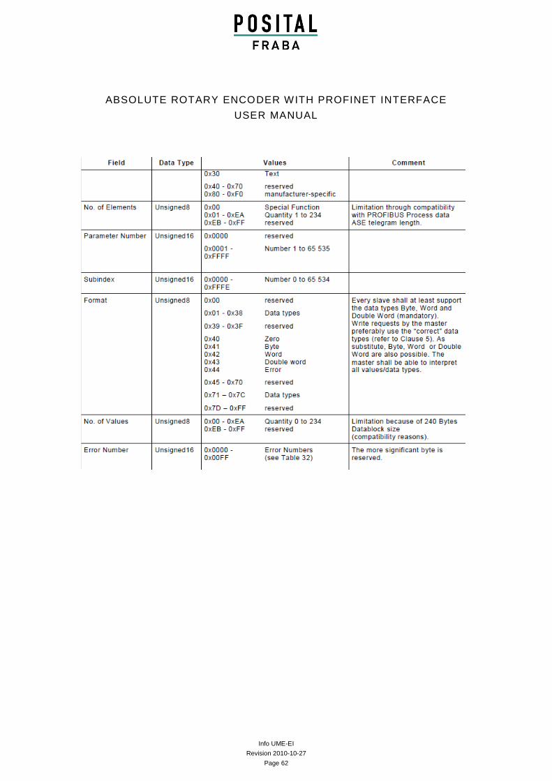
5.3.5 Coding
The coding of the fields in parameter request /
parameter response of Base Mode Parameter
Access:
Info UME-EI
Revision 2010-10-27
Page 62
ABSOLUTE ROTARY ENCODER WITH PROFINET INTERFACE
USER MANUAL
Info UME-EI
Revision 2010-10-27
Page 63
ABSOLUTE ROTARY ENCODER WITH PROFINET INTERFACE
USER MANUAL
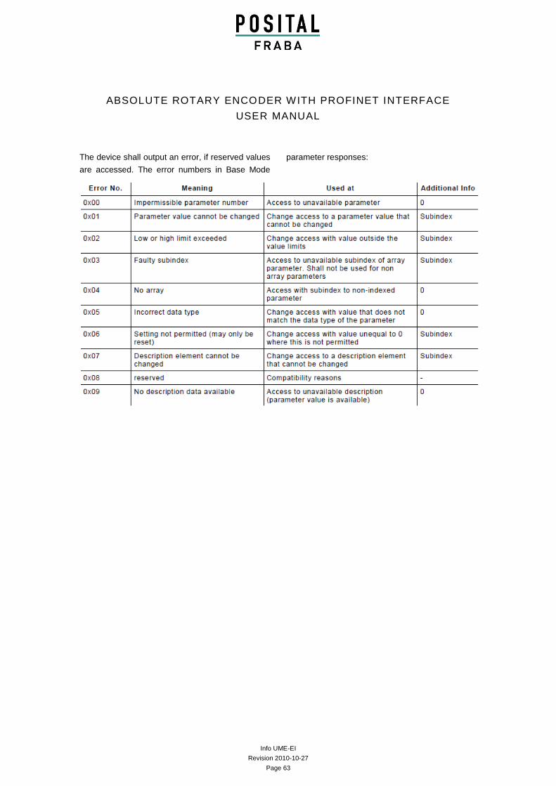
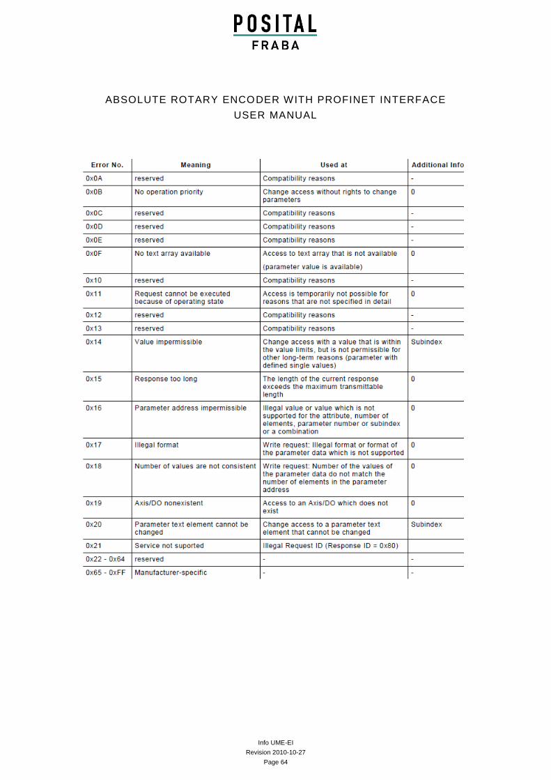
The device shall output an error, if reserved values
are accessed. The error numbers in Base Mode
parameter responses:
Info UME-EI
Revision 2010-10-27
Page 64
ABSOLUTE ROTARY ENCODER WITH PROFINET INTERFACE
USER MANUAL
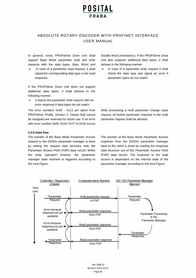
Info UME-EI
Revision 2010-10-27
Page 65
ABSOLUTE ROTARY ENCODER WITH PROFINET INTERFACE
USER MANUAL
In general, every PROFIdrive Drive Unit shall
support Base Mode parameter read and write
requests with the data types, Byte, Word and
Double Word (mandatory). If the PROFIdrive Drive
Unit also supports additional data types, it shall
behave in the following manner:
In case of a parameter read request, it shall
signal the corresponding data type in the read
response.
In case of a parameter write request it shall
check the data type and signal an error if
parameter types do not match.
If the PROFIdrive Drive Unit does not support
additional data types, it shall behave in the
following manner:
It rejects the parameter write request with an
error response if data types do not match.
The error numbers 0x00 - 0x13 are taken from
PROFIdrive Profile, Version 2. Values that cannot
be assigned are reserved for future use. If an error
with error number 0x05, 0x16, 0x17 or 0x18 occurs
while processing a multi parameter change value
request, all further parameter requests in the multi
parameter request shall be aborted.
5.3.6 Data flow
The transfer of the Base Mode Parameter Access
request to the DO/DU parameter manager is done
by writing the request data structure onto the
Parameter Access Point (PAP) data record. When
the write operation finishes, the parameter
manager state machine is triggered according to
the next Figure.
The transfer of the Base Mode Parameter Access
response from the DO/DU parameter manager
back to the client is done by reading the response
data structure out of the Parameter Access Point
(PAP) data record. The response to the read
access is dependent on the internal state of the
parameter manager according to the next Figure.
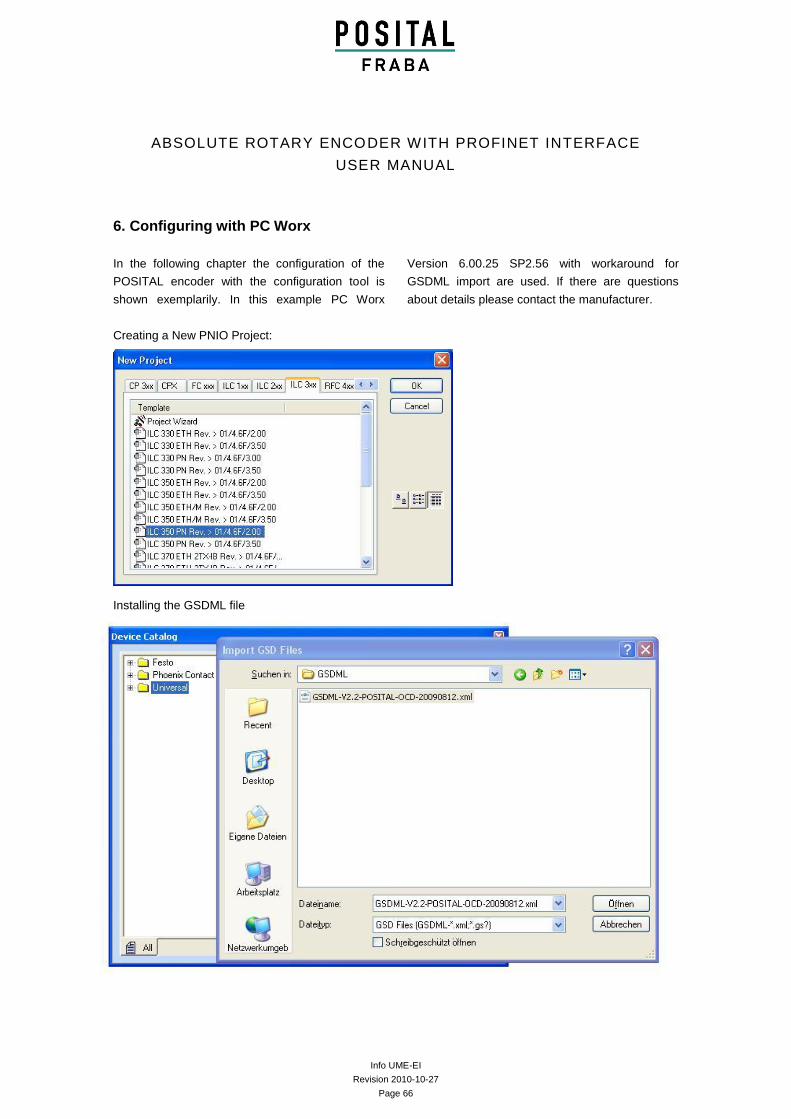
Info UME-EI
Revision 2010-10-27
Page 66
ABSOLUTE ROTARY ENCODER WITH PROFINET INTERFACE
USER MANUAL
6. Configuring with PC Worx
In the following chapter the configuration of the
POSITAL encoder with the configuration tool is
shown exemplarily. In this example PC Worx
Version 6.00.25 SP2.56 with workaround for
GSDML import are used. If there are questions
about details please contact the manufacturer.
Creating a New PNIO Project:
Installing the GSDML file
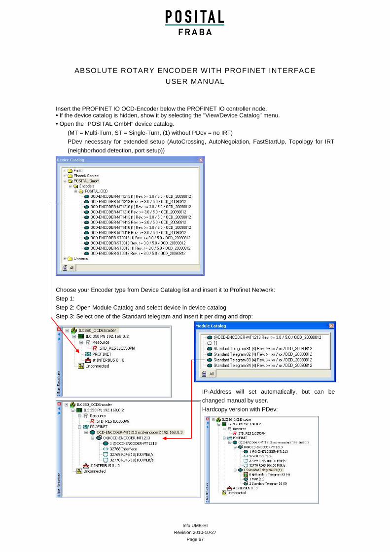
Info UME-EI
Revision 2010-10-27
Page 67
ABSOLUTE ROTARY ENCODER WITH PROFINET INTERFACE
USER MANUAL
Insert the PROFINET IO OCD-Encoder below the PROFINET IO controller node. • If the device catalog is hidden, show it by selecting the "View/Device Catalog" menu.
• Open the "POSITAL GmbH" device catalog.
(MT = Multi-Turn, ST = Single-Turn, (1) without PDev = no IRT)
PDev necessary for extended setup (AutoCrossing, AutoNegoiation, FastStartUp, Topology for IRT
(neighborhood detection, port setup))
Choose your Encoder type from Device Catalog list and insert it to Profinet Network:
Step 1:
Step 2: Open Module Catalog and select device in device catalog
Step 3: Select one of the Standard telegram and insert it per drag and drop:
IP-Address will set automatically, but can be
changed manual by user.
Hardcopy version with PDev:
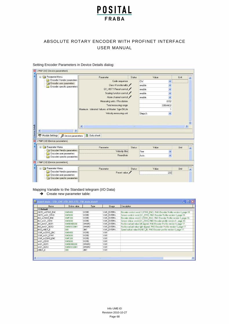
Info UME-EI
Revision 2010-10-27
Page 68
ABSOLUTE ROTARY ENCODER WITH PROFINET INTERFACE
USER MANUAL
Setting Encoder Parameters in Device Details dialog:
Mapping Variable to the Standard telegram (I/O Data)
Create new parameter table:
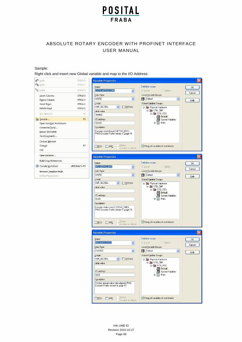
Info UME-EI
Revision 2010-10-27
Page 69
ABSOLUTE ROTARY ENCODER WITH PROFINET INTERFACE
USER MANUAL
Sample:
Right click and insert new Global variable and map to the I/O Address:
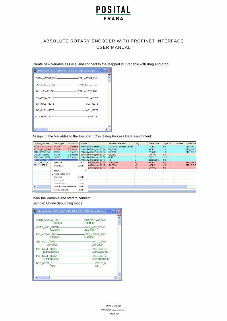
Info UME-EI
Revision 2010-10-27
Page 70
ABSOLUTE ROTARY ENCODER WITH PROFINET INTERFACE
USER MANUAL
Create new Variable as Local and connect to the Mapped I/O Variable with drag and drop:
Assigning the Variables to the Encoder I/O in dialog Process Data assignment:
Mark the Variable and start to connect.
Sample: Online debugging mode
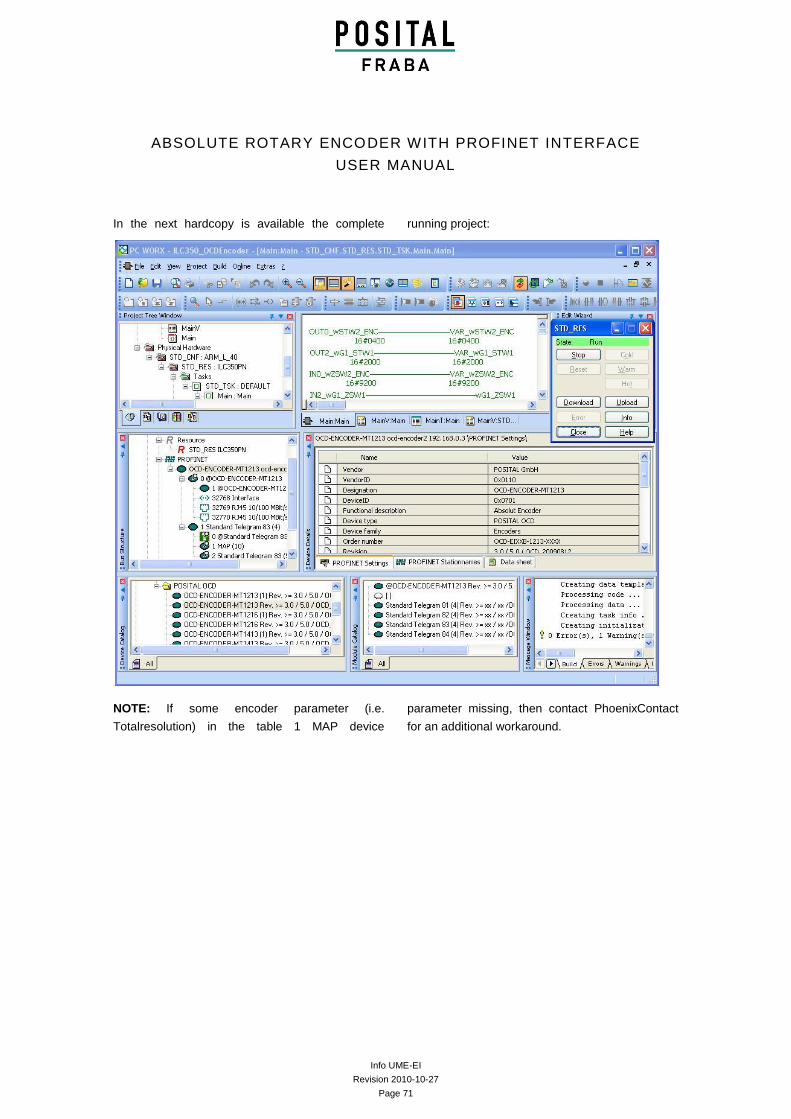
Info UME-EI
Revision 2010-10-27
Page 71
ABSOLUTE ROTARY ENCODER WITH PROFINET INTERFACE
USER MANUAL
In the next hardcopy is available the complete running project:
NOTE: If some encoder parameter (i.e.
Totalresolution) in the table 1 MAP device
parameter missing, then contact PhoenixContact
for an additional workaround.
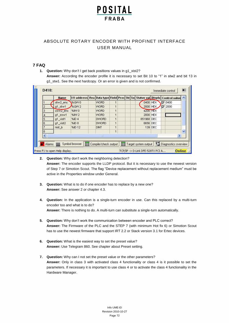
Info UME-EI
Revision 2010-10-27
Page 72
ABSOLUTE ROTARY ENCODER WITH PROFINET INTERFACE
USER MANUAL
7 FAQ
1. Question: Why don’t I get back positions values in g1_xist2?
Answer: According the encoder profile it is necessary to set Bit 10 to “1” in stw2 and bit 13 in
g1_stw1. See the next hardcopy. Or an error is given and is not confirmed.
2. Question: Why don’t work the neighboring detection?
Answer: The encoder supports the LLDP protocol. But it is necessary to use the newest version
of Step 7 or Simotion Scout. The flag “Device replacement without replacement medium” must be
active in the Properties window under General.
3. Question: What is to do if one encoder has to replace by a new one?
Answer: See answer 2 or chapter 4.3.
4. Question: In the application is a single-turn encoder in use. Can this replaced by a multi-turn
encoder too and what is to do?
Answer: There is nothing to do. A multi-turn can substitute a single-turn automatically.
5. Question: Why don’t work the communication between encoder and PLC correct?
Answer: The Firmware of the PLC and the STEP 7 (with minimum Hot fix 6) or Simotion Scout
has to use the newest firmware that support IRT 2.2 or Stack version 3.1 for Ertec devices.
6. Question: What is the easiest way to set the preset value?
Answer: Use Telegram 860. See chapter about Preset setting.
7. Question: Why can I not set the preset value or the other parameters?
Answer: Only in class 3 with activated class 4 functionality or class 4 is it possible to set the
parameters. If necessary it is important to use class 4 or to activate the class 4 functionality in the
Hardware Manager.
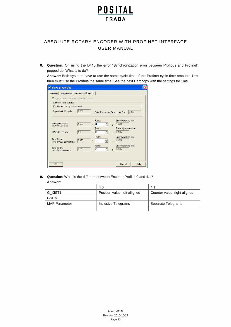
Info UME-EI
Revision 2010-10-27
Page 73
ABSOLUTE ROTARY ENCODER WITH PROFINET INTERFACE
USER MANUAL
8. Question: On using the D410 the error “Synchronization error between Profibus and Profinet”
popped up. What is to do?
Answer: Both systems have to use the same cycle time. If the Profinet cycle time amounts 1ms
then must use the Profibus the same time. See the next Hardcopy with the settings for 1ms.
9. Question: What is the different between Encoder Profil 4.0 and 4.1?
Answer:
4.0 4.1
G_XIST1 Position value, left alligned Counter value, right aligned
GSDML
MAP Parameter Inclusive Telegrams Separate Telegrams
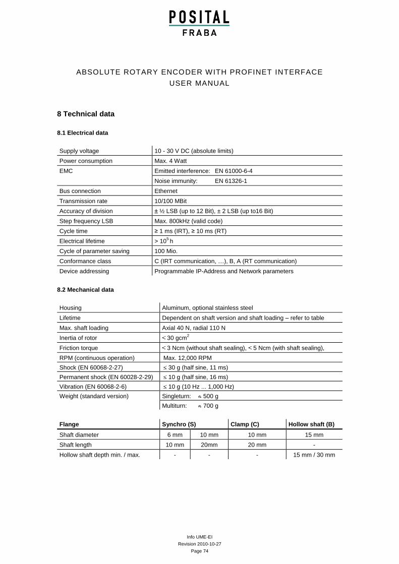
Info UME-EI
Revision 2010-10-27
Page 74
ABSOLUTE ROTARY ENCODER WITH PROFINET INTERFACE
USER MANUAL
8 Technical data
8.1 Electrical data
Supply voltage 10 - 30 V DC (absolute limits)
Power consumption Max. 4 Watt
EMC Emitted interference: EN 61000-6-4
Noise immunity: EN 61326-1
Bus connection Ethernet
Transmission rate 10/100 MBit
Accuracy of division ½ LSB (up to 12 Bit), ± 2 LSB (up to16 Bit)
Step frequency LSB Max. 800kHz (valid code)
Cycle time ≥ 1 ms (IRT), ≥ 10 ms (RT)
Electrical lifetime > 105 h
Cycle of parameter saving 100 Mio.
Conformance class C (IRT communication, …), B, A (RT communication)
Device addressing Programmable IP-Address and Network parameters
8.2 Mechanical data
Housing Aluminum, optional stainless steel
Lifetime Dependent on shaft version and shaft loading – refer to table
Max. shaft loading Axial 40 N, radial 110 N
Inertia of rotor 30 gcm2
Friction torque 3 Ncm (without shaft sealing), 5 Ncm (with shaft sealing),
RPM (continuous operation) Max. 12,000 RPM
Shock (EN 60068-2-27) 30 g (half sine, 11 ms)
Permanent shock (EN 60028-2-29) 10 g (half sine, 16 ms)
Vibration (EN 60068-2-6) 10 g (10 Hz ... 1,000 Hz)
Weight (standard version) Singleturn: 500 g
Multiturn: 700 g
Flange Synchro (S) Clamp (C) Hollow shaft (B)
Shaft diameter 6 mm 10 mm 10 mm 15 mm
Shaft length 10 mm 20mm 20 mm -
Hollow shaft depth min. / max. - - - 15 mm / 30 mm
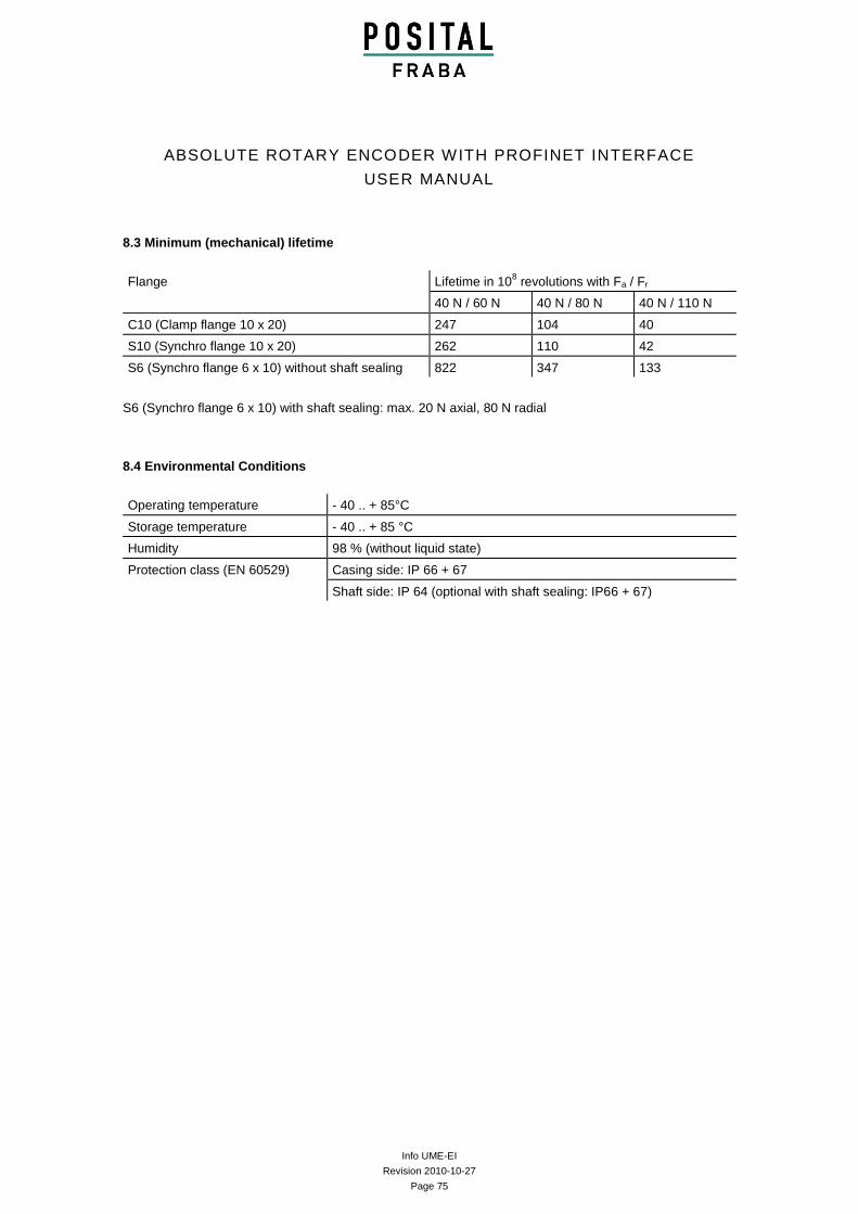
Info UME-EI
Revision 2010-10-27
Page 75
ABSOLUTE ROTARY ENCODER WITH PROFINET INTERFACE
USER MANUAL
8.3 Minimum (mechanical) lifetime
Flange Lifetime in 108 revolutions with Fa / Fr
40 N / 60 N 40 N / 80 N 40 N / 110 N
C10 (Clamp flange 10 x 20) 247 104 40
S10 (Synchro flange 10 x 20) 262 110 42
S6 (Synchro flange 6 x 10) without shaft sealing 822 347 133
S6 (Synchro flange 6 x 10) with shaft sealing: max. 20 N axial, 80 N radial
8.4 Environmental Conditions
Operating temperature - 40 .. + 85°C
Storage temperature - 40 .. + 85 °C
Humidity 98 % (without liquid state)
Protection class (EN 60529) Casing side: IP 66 + 67
Shaft side: IP 64 (optional with shaft sealing: IP66 + 67)
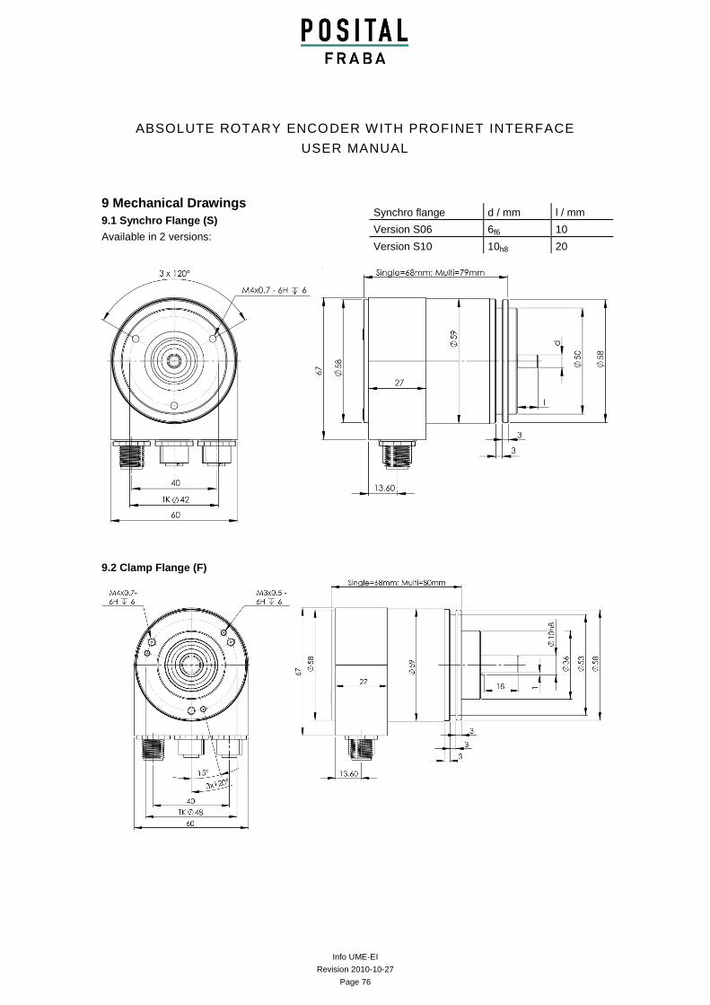
Info UME-EI
Revision 2010-10-27
Page 76
ABSOLUTE ROTARY ENCODER WITH PROFINET INTERFACE
USER MANUAL
9 Mechanical Drawings
9.1 Synchro Flange (S)
Available in 2 versions:
9.2 Clamp Flange (F)
Synchro flange d / mm l / mm
Version S06 6f6 10
Version S10 10h8 20
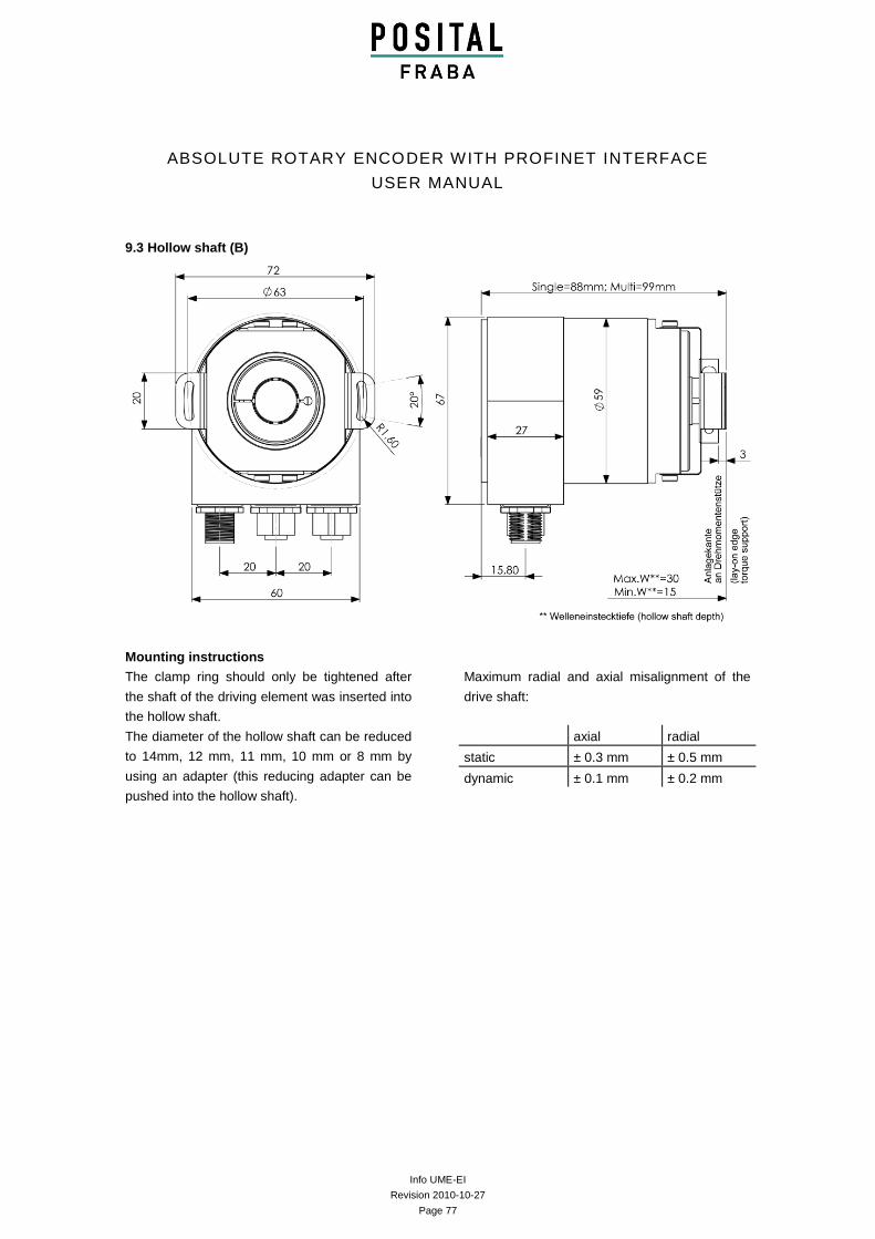
Info UME-EI
Revision 2010-10-27
Page 77
ABSOLUTE ROTARY ENCODER WITH PROFINET INTERFACE
USER MANUAL
9.3 Hollow shaft (B)
Mounting instructions
The clamp ring should only be tightened after
the shaft of the driving element was inserted into
the hollow shaft.
The diameter of the hollow shaft can be reduced
to 14mm, 12 mm, 11 mm, 10 mm or 8 mm by
using an adapter (this reducing adapter can be
pushed into the hollow shaft).
Maximum radial and axial misalignment of the
drive shaft:
axial radial
static ± 0.3 mm ± 0.5 mm
dynamic ± 0.1 mm ± 0.2 mm
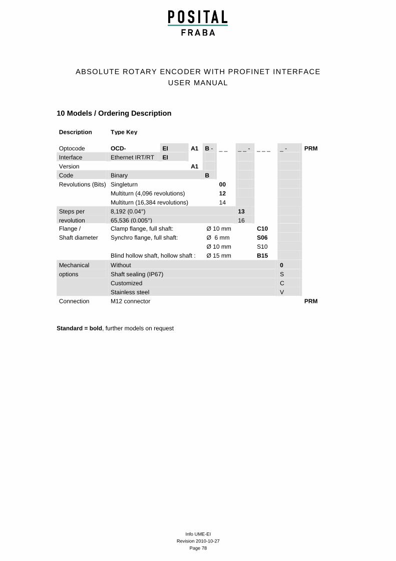
Info UME-EI
Revision 2010-10-27
Page 78
ABSOLUTE ROTARY ENCODER WITH PROFINET INTERFACE
USER MANUAL
10 Models / Ordering Description
Description Type Key
Optocode OCD- EI A1 B - _ _ _ _ - _ _ _ _ - PRM
Interface Ethernet IRT/RT EI
Version A1
Code Binary B
Revolutions (Bits) Singleturn 00
Multiturn (4,096 revolutions)
Multiturn (16,384 revolutions)
12
14
Steps per
revolution
(Bits)
8,192 (0.04°) 13
65,536 (0.005°) 16
Flange /
Shaft diameter
Clamp flange, full shaft: Ø 10 mm C10
Synchro flange, full shaft: Ø 6 mm
Ø 10 mm
S06
S10
Blind hollow shaft, hollow shaft : Ø 15 mm B15
Mechanical
options
Without 0
Shaft sealing (IP67) S
Customized
Stainless steel
C
V
Connection M12 connector PRM
Standard = bold, further models on request
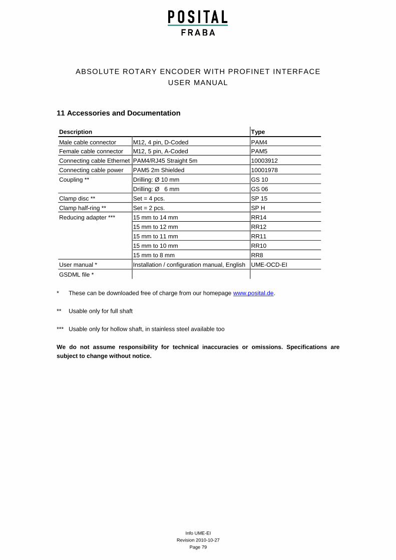
Info UME-EI
Revision 2010-10-27
Page 79
ABSOLUTE ROTARY ENCODER WITH PROFINET INTERFACE
USER MANUAL
11 Accessories and Documentation
Description Type
Male cable connector M12, 4 pin, D-Coded PAM4
Female cable connector M12, 5 pin, A-Coded PAM5
Connecting cable Ethernet PAM4/RJ45 Straight 5m 10003912
Connecting cable power PAM5 2m Shielded 10001978
Coupling ** Drilling: Ø 10 mm GS 10
Drilling: Ø 6 mm GS 06
Clamp disc ** Set = 4 pcs. SP 15
Clamp half-ring ** Set = 2 pcs. SP H
Reducing adapter *** 15 mm to 14 mm RR14
15 mm to 12 mm RR12
15 mm to 11 mm RR11
15 mm to 10 mm RR10
15 mm to 8 mm RR8
User manual * Installation / configuration manual, English UME-OCD-EI
GSDML file *
* These can be downloaded free of charge from our homepage www.posital.de.
** Usable only for full shaft
*** Usable only for hollow shaft, in stainless steel available too
We do not assume responsibility for technical inaccuracies or omissions. Specifications are
subject to change without notice.
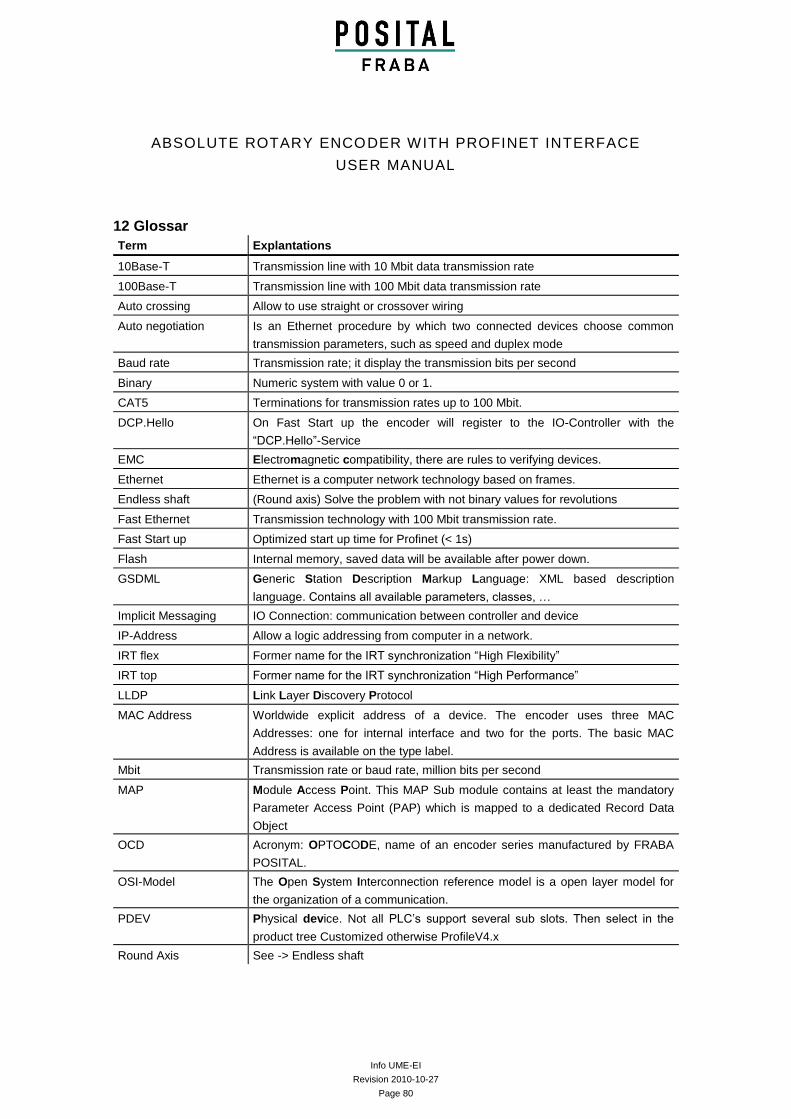
Info UME-EI
Revision 2010-10-27
Page 80
ABSOLUTE ROTARY ENCODER WITH PROFINET INTERFACE
USER MANUAL
12 Glossar
Term Explantations
10Base-T Transmission line with 10 Mbit data transmission rate
100Base-T Transmission line with 100 Mbit data transmission rate
Auto crossing Allow to use straight or crossover wiring
Auto negotiation Is an Ethernet procedure by which two connected devices choose common
transmission parameters, such as speed and duplex mode
Baud rate Transmission rate; it display the transmission bits per second
Binary Numeric system with value 0 or 1.
CAT5 Terminations for transmission rates up to 100 Mbit.
DCP.Hello On Fast Start up the encoder will register to the IO-Controller with the
“DCP.Hello”-Service
EMC Electromagnetic compatibility, there are rules to verifying devices.
Ethernet Ethernet is a computer network technology based on frames.
Endless shaft (Round axis) Solve the problem with not binary values for revolutions
Fast Ethernet Transmission technology with 100 Mbit transmission rate.
Fast Start up Optimized start up time for Profinet (< 1s)
Flash Internal memory, saved data will be available after power down.
GSDML Generic Station Description Markup Language: XML based description
language. Contains all available parameters, classes, …
Implicit Messaging IO Connection: communication between controller and device
IP-Address Allow a logic addressing from computer in a network.
IRT flex Former name for the IRT synchronization “High Flexibility”
IRT top Former name for the IRT synchronization “High Performance”
LLDP Link Layer Discovery Protocol
MAC Address Worldwide explicit address of a device. The encoder uses three MAC
Addresses: one for internal interface and two for the ports. The basic MAC
Address is available on the type label.
Mbit Transmission rate or baud rate, million bits per second
MAP Module Access Point. This MAP Sub module contains at least the mandatory
Parameter Access Point (PAP) which is mapped to a dedicated Record Data
Object
OCD Acronym: OPTOCODE, name of an encoder series manufactured by FRABA
POSITAL.
OSI-Model The Open System Interconnection reference model is a open layer model for
the organization of a communication.
PDEV Physical device. Not all PLC’s support several sub slots. Then select in the
product tree Customized otherwise ProfileV4.x
Round Axis See -> Endless shaft
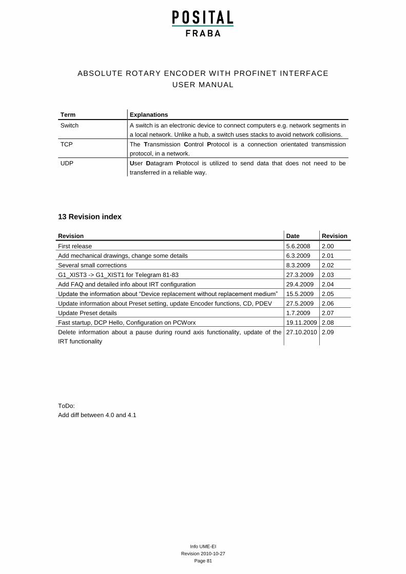
Info UME-EI
Revision 2010-10-27
Page 81
ABSOLUTE ROTARY ENCODER WITH PROFINET INTERFACE
USER MANUAL
Term Explanations
Switch A switch is an electronic device to connect computers e.g. network segments in
a local network. Unlike a hub, a switch uses stacks to avoid network collisions.
TCP The Transmission Control Protocol is a connection orientated transmission
protocol, in a network.
UDP User Datagram Protocol is utilized to send data that does not need to be
transferred in a reliable way.
13 Revision index
Revision Date Revision
First release 5.6.2008 2.00
Add mechanical drawings, change some details 6.3.2009 2.01
Several small corrections 8.3.2009 2.02
G1_XIST3 -> G1_XIST1 for Telegram 81-83 27.3.2009 2.03
Add FAQ and detailed info about IRT configuration 29.4.2009 2.04
Update the information about “Device replacement without replacement medium” 15.5.2009 2.05
Update information about Preset setting, update Encoder functions, CD, PDEV 27.5.2009 2.06
Update Preset details 1.7.2009 2.07
Fast startup, DCP Hello, Configuration on PCWorx 19.11.2009 2.08
Delete information about a pause during round axis functionality, update of the
IRT functionality
27.10.2010 2.09
ToDo:
Add diff between 4.0 and 4.1