Embed Size (px)
Citation preview
AMERICA
FRABA Inc.
1800 East State Street, Suite 148
Hamilton, NJ 08609-2020, USA
T +1-609-750-8705, F +1-609-750-8703
www.posital.com, [email protected]
EUROPE
POSITAL GmbH
Carlswerkstrasse 13c
51063 Cologne, Germany
T +49 221 96213-0, F +49 221 96213-20
www.posital.com, [email protected]
ASIA
FRABA Pte. Ltd.
20 Kallang Avenue
Singapore 339411, Singapore
T +65 65148880, F +65 62711792
www.posital.sg, [email protected]
ABSOLUTE IXARC ROTARY ENCODER
CANOPEN INTERFACE
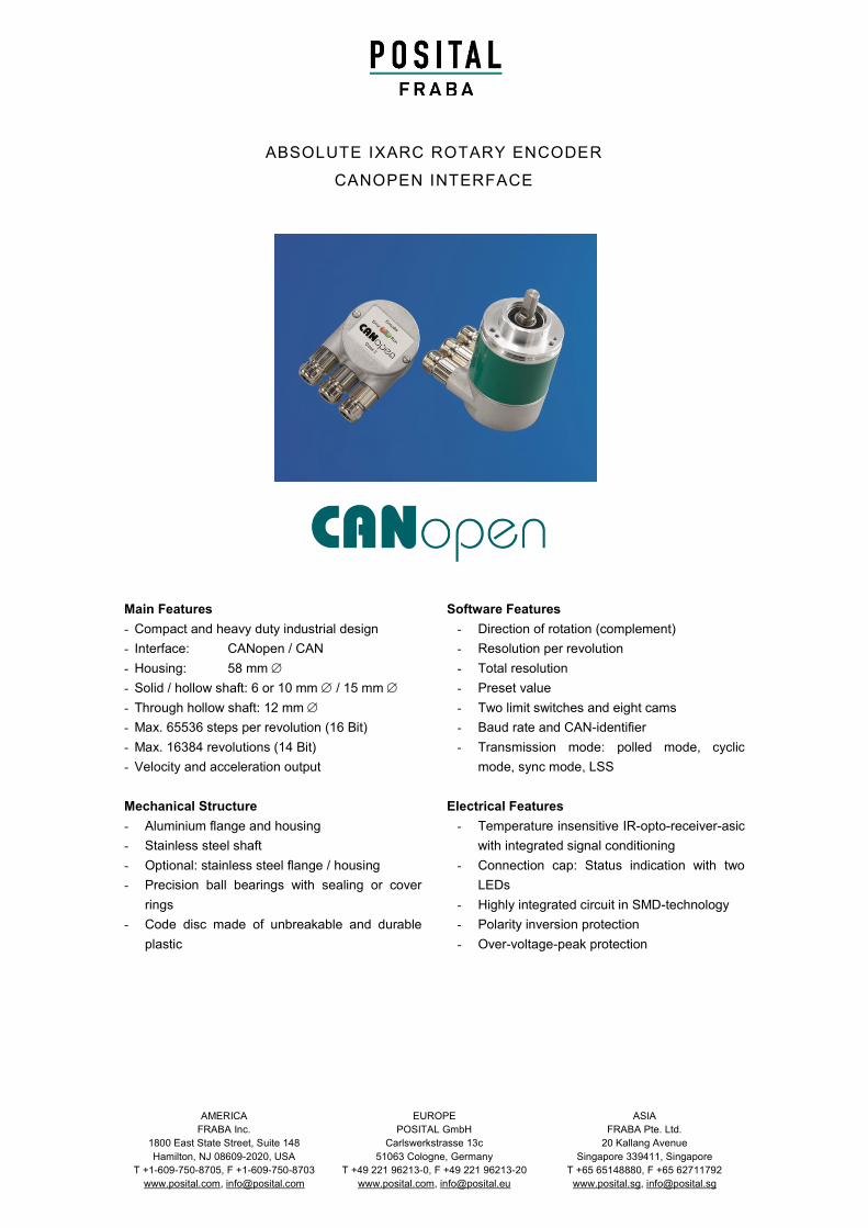
Main Features
- Compact and heavy duty industrial design
- Interface: CANopen / CAN
- Housing: 58 mm
- Solid / hollow shaft: 6 or 10 mm / 15 mm
- Through hollow shaft: 12 mm
- Max. 65536 steps per revolution (16 Bit)
- Max. 16384 revolutions (14 Bit)
- Velocity and acceleration output
Mechanical Structure
- Aluminium flange and housing
- Stainless steel shaft
- Optional: stainless steel flange / housing
- Precision ball bearings with sealing or cover
rings
- Code disc made of unbreakable and durable
plastic
Software Features
- Direction of rotation (complement)
- Resolution per revolution
- Total resolution
- Preset value
- Two limit switches and eight cams
- Baud rate and CAN-identifier
- Transmission mode: polled mode, cyclic
mode, sync mode, LSS
Electrical Features
- Temperature insensitive IR-opto-receiver-asic
with integrated signal conditioning
- Connection cap: Status indication with two
LEDs
- Highly integrated circuit in SMD-technology
- Polarity inversion protection
- Over-voltage-peak protection
Version: 2.7.10 E Info OCD CA Page 2
ABSOLUTE IXRAC ROTARY ENCODER
CANOPEN INTERFACE
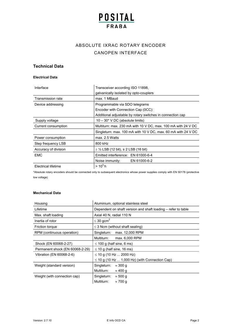
Technical Data
Electrical Data
Interface Transceiver according ISO 11898,
galvanically isolated by opto-couplers
Transmission rate max. 1 MBaud
Device addressing Programmable via SDO telegrams
Encoder with Connection Cap (0CC):
Additional adjustable by rotary switches in connection cap
Supply voltage 10 – 30* V DC (absolute limits)
Current consumption Multiturn: max. 230 mA with 10 V DC, max. 100 mA with 24 V DC
Singleturn: max. 100 mA with 10 V DC, max. 60 mA with 24 V DC
Power consumption max. 2.5 Watts
Step frequency LSB 800 kHz
Accuracy of division ½ LSB (12 bit), ± 2 LSB (16 bit)
EMC Emitted interference: EN 61000-6-4
Noise immunity: EN 61000-6-2
Electrical lifetime > 105 h
*Absolute rotary encoders should be connected only to subsequent electronics whose power supplies comply with EN 50178 (protective
low voltage)
Mechanical Data
Housing Aluminium, optional stainless steel
Lifetime Dependent on shaft version and shaft loading – refer to table
Max. shaft loading Axial 40 N, radial 110 N
Inertia of rotor 30 gcm2
Friction torque 3 Ncm (without shaft sealing)
RPM (continuous operation) Singleturn: max. 12,000 RPM
Multiturn: max. 6,000 RPM
Shock (EN 60068-2-27) 100 g (half sine, 6 ms)
Permanent shock (EN 60068-2-29) 10 g (half sine, 16 ms)
Vibration (EN 60068-2-6) 10 g (10 Hz ... 2000 Hz)
10 g (10 Hz ... 1,000 Hz) (with Connection Cap)
Weight (standard version) Singleturn: 300 g
Multiturn: 400 g
Weight (with connection cap) Singleturn: 500 g
Multiturn: 700 g
Version: 2.7.10 E Info OCD CA Page 3
ABSOLUTE IXARC ROTARY ENCODER
CANOPEN INTERFACE
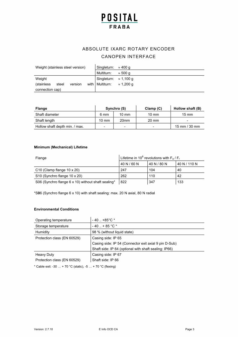
Weight (stainless steel version) Singleturn: 400 g
Multiturn: 500 g
Weight
(stainless steel version with
connection cap)
Singleturn: 1,100 g
Multiturn: 1,200 g
Flange Synchro (S) Clamp (C) Hollow shaft (B)
Shaft diameter 6 mm 10 mm 10 mm 15 mm
Shaft length 10 mm 20mm 20 mm -
Hollow shaft depth min. / max. - - - 15 mm / 30 mm
Minimum (Mechanical) Lifetime
Flange Lifetime in 108 revolutions with Fa / Fr
40 N / 60 N 40 N / 80 N 40 N / 110 N
C10 (Clamp flange 10 x 20) 247 104 40
S10 (Synchro flange 10 x 20) 262 110 42
S06 (Synchro flange 6 x 10) without shaft sealing* 822 347 133
*S06 (Synchro flange 6 x 10) with shaft sealing: max. 20 N axial, 80 N radial
Environmental Conditions
Operating temperature - 40 .. +85°C *
Storage temperature - 40 .. + 85 °C *
Humidity 98 % (without liquid state)
Protection class (EN 60529) Casing side: IP 65
Casing side: IP 54 (Connector exit axial 9 pin D-Sub)
Shaft side: IP 64 (optional with shaft sealing: IP66)
Heavy Duty
Protection class (EN 60529)
Casing side: IP 67
Shaft side: IP 66
* Cable exit: -30 … + 70 °C (static), -5 … + 70 °C (flexing)

Version: 2.7.10 E Info OCD CA Page 4
ABSOLUTE IXRAC ROTARY ENCODER
CANOPEN INTERFACE
Conformity
UL International -For use in NFPA 79 Applications only
-Adapters providing field wiring means are available from
the manufacturer. Refer to manufacturers information.
CE
ABSOLUTE IXARC ROTARY ENCODER
CANOPEN INTERFACE
Interface
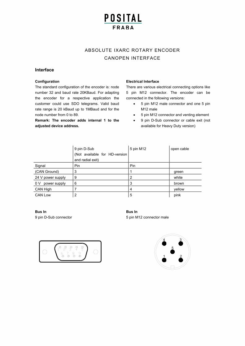
Configuration
The standard configuration of the encoder is: node
number 32 and baud rate 20KBaud. For adapting
the encoder for a respective application the
customer could use SDO telegrams. Valid baud
rate range is 20 kBaud up to 1MBaud and for the
node number from 0 to 89.
Remark: The encoder adds internal 1 to the
adjusted device address.
Bus In
9 pin D-Sub connector
Electrical Interface
There are various electrical connecting options like
5 pin M12 connector. The encoder can be
connected in the following versions:
5 pin M12 male connector and one 5 pin
M12 male
5 pin M12 connector and venting element
9 pin D-Sub connector or cable exit (not
available for Heavy Duty version)
Bus In
5 pin M12 connector male
9 pin D-Sub
(Not available for HD-version
and radial exit)
5 pin M12
open cable
Signal Pin Pin
(CAN Ground) 3 1 green
24 V power supply 9 2 white
0 V power supply 6 3 brown
CAN High 7 4 yellow
CAN Low 2 5 pink
1
4
2
3
5
Version: 2.7.10 E Info OCD CA Page 6
ABSOLUTE IXRAC ROTARY ENCODER
CANOPEN INTERFACE
ON
TR T
ON
R
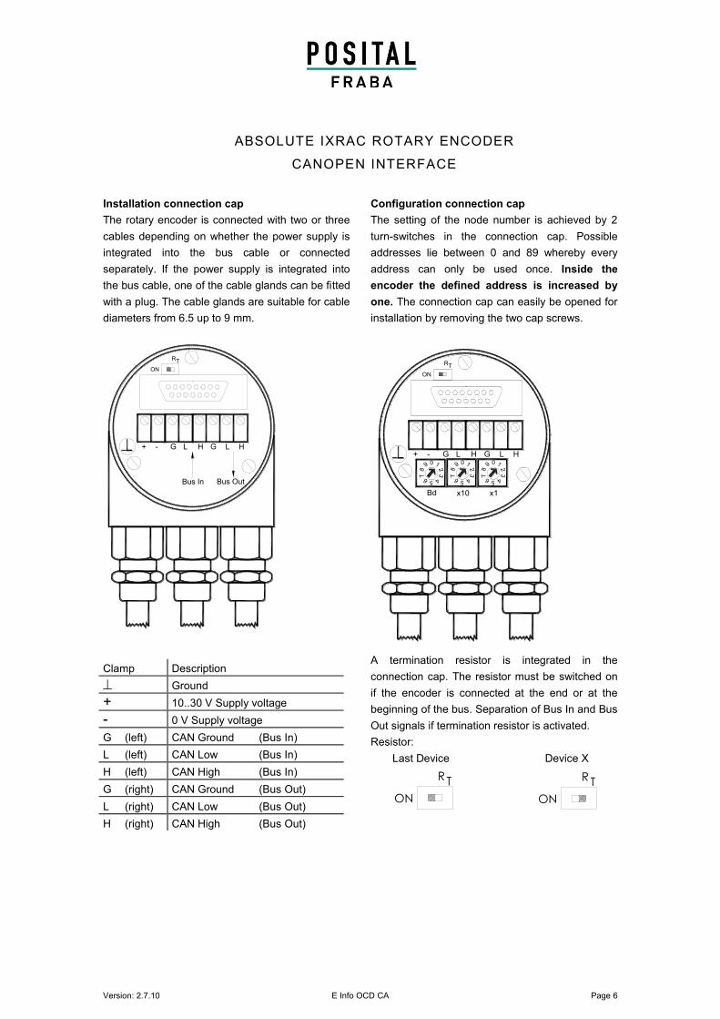
Installation connection cap
The rotary encoder is connected with two or three
cables depending on whether the power supply is
integrated into the bus cable or connected
separately. If the power supply is integrated into
the bus cable, one of the cable glands can be fitted
with a plug. The cable glands are suitable for cable
diameters from 6.5 up to 9 mm.
Configuration connection cap
The setting of the node number is achieved by 2
turn-switches in the connection cap. Possible
addresses lie between 0 and 89 whereby every
address can only be used once. Inside the
encoder the defined address is increased by
one. The connection cap can easily be opened for
installation by removing the two cap screws.
A termination resistor is integrated in the
connection cap. The resistor must be switched on
if the encoder is connected at the end or at the
beginning of the bus. Separation of Bus In and Bus
Out signals if termination resistor is activated.
Resistor:
Last Device Device X
Clamp Description
Ground
+ 10..30 V Supply voltage
- 0 V Supply voltage
G (left) CAN Ground (Bus In)
L (left) CAN Low (Bus In)
H (left) CAN High (Bus In)
G (right) CAN Ground (Bus Out)
L (right) CAN Low (Bus Out)
H (right) CAN High (Bus Out)
GH-+ G L L H
ON
09
87
6 5 4
32
1
78
2
56 4
3
09 1
x10 x1
87
2
6 5 4
3
09 1
Bd
RT
GH-+ G L L H
ON
RT
Bus In Bus Out
ABSOLUTE IXARC ROTARY ENCODER
CANOPEN INTERFACE
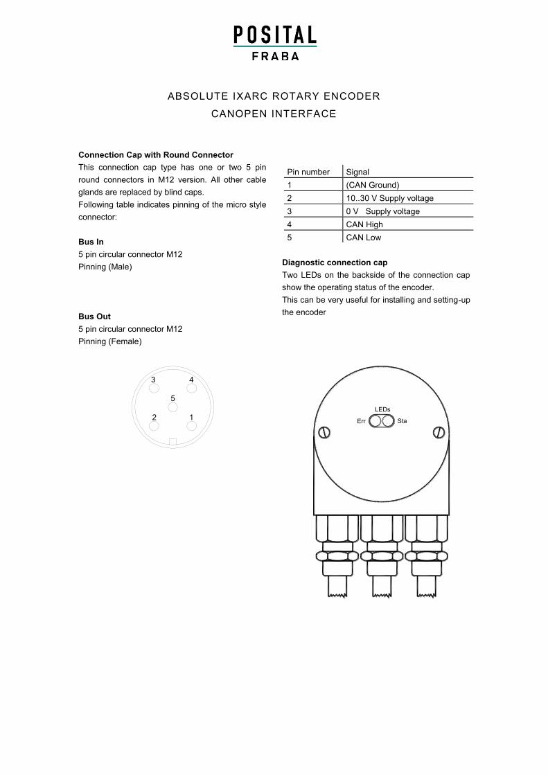
Connection Cap with Round Connector
This connection cap type has one or two 5 pin
round connectors in M12 version. All other cable
glands are replaced by blind caps.
Following table indicates pinning of the micro style
connector:
Bus In
5 pin circular connector M12
Pinning (Male)
Bus Out
5 pin circular connector M12
Pinning (Female)
Diagnostic connection cap
Two LEDs on the backside of the connection cap
show the operating status of the encoder.
This can be very useful for installing and setting-up
the encoder
Pin number Signal
1 (CAN Ground)
2 10..30 V Supply voltage
3 0 V Supply voltage
4 CAN High
5 CAN Low
2
3
1
4
5
LEDs
Err Sta
Version: 2.7.10 E Info OCD CA Page 8
ABSOLUTE IXRAC ROTARY ENCODER
CANOPEN INTERFACE
Programmable Encoder - Parameter
Operating Parameters This parameter determines the counting direction, in which the output code
increases or decreases. As an important operating parameter the code
sequence (complement) can be programmed.
Resolution per Revolution The parameter resolution per revolution is used to program the desired
number of steps per revolution.
Total Resolution This parameter is used to program the desired number of measuring units
over the total measuring range. This value may not exceed the total
resolution of the absolute rotary encoder. If the encoder is used in a
continuous measuring application, certain rules for the setting of this
parameter must be followed. These rules are outlined in the manual.
Preset Value The preset value is the desired position value, which should be reached at a
certain physical position of the axis. The position value is set to the desired
process value by the parameter pre-set.
Limit Switch,
Min. and Max.
Two position values can be programmed as limit switches. By reaching
these values one bit of the 32-bit process value is set to high.
Cam Eight position values can be programmed as cams. By reaching these
values bits in object 6300h Cam state register are set.
Programmable CAN Transmission Modes
Polled Mode By a remote-transmission-request telegram the connected host calls for the
current process value. The absolute rotary encoder reads the current
position value, calculates eventually set-parameters and sends back the
obtained process value by the same identifier.
Cyclic Mode The absolute rotary encoder transmits cyclically - without being called by the
host - the current process value. The cycle time can be programmed in
milliseconds for values between 1 ms and 65536 ms.
Sync Mode After receiving a sync telegram by the host, the absolute rotary encoder
answers with the current process value. If more than one node number
(encoder) shall answer after receiving a sync telegram, the answer
telegrams of the nodes will be received by the host in order of their node
numbers. The programming of an offset-time is not necessary. If a node
should not answer after each sync telegram on the CAN network, the
parameter sync counter can be programmed to skip a certain number of
sync telegrams before answering again.
Version: 2.7.10 E Info OCD CA Page 9
ABSOLUTE IXARC ROTARY ENCODER
CANOPEN INTERFACE
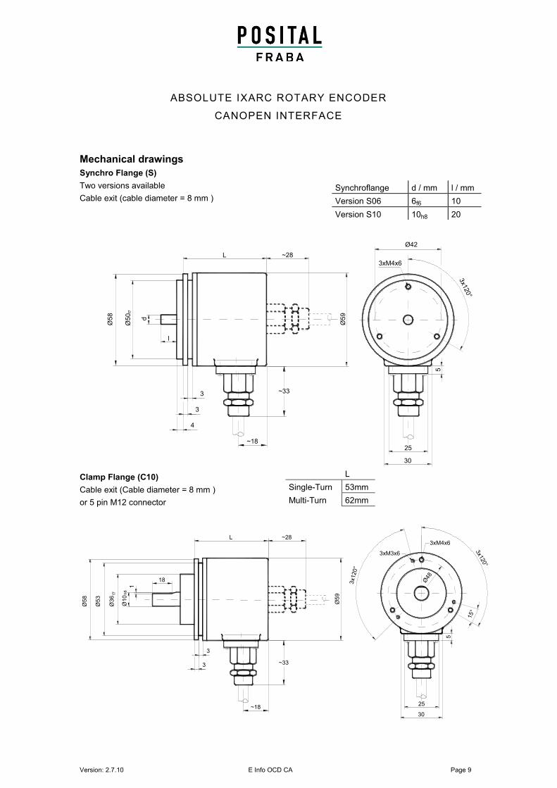
Mechanical drawings
Synchro Flange (S)
Two versions available
Cable exit (cable diameter = 8 mm )
Clamp Flange (C10)
Cable exit (Cable diameter = 8 mm )
or 5 pin M12 connector
Synchroflange d / mm l / mm
Version S06 6f6 10
Version S10 10h8 20
Ø5
9
L ~28
30
25
5~18
~33
4
3
Ø42
l
3
Ø5
8
3xM4x6
3x1
20°
f7Ø
50
d
L
Single-Turn 53mm
Multi-Turn 62mm
Ø3
6f7
1
Ø1
0h
8
3
Ø5
8
Ø5
3
Ø5
9
3
18
L ~28
5
25
30
3x120°
3xM3x6
3xM4x6
3x1
20°
15°
Ø48
~18
~33
Version: 2.7.10 E Info OCD CA Page 10
ABSOLUTE IXARC ROTARY ENCODER
CANOPEN INTERFACE
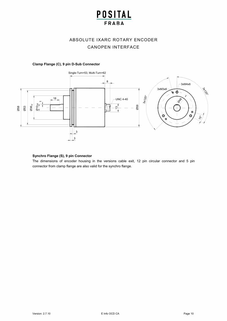
Clamp Flange (C), 9 pin D-Sub Connector
Synchro Flange (S), 9 pin Connector
The dimensions of encoder housing in the versions cable exit, 12 pin circular connector and 5 pin
connector from clamp flange are also valid for the synchro flange.
Ø36
f7
1
Ø10
h8
3
Ø58
Ø53
Ø5
93
18
Single-Turn=53, Multi-Turn=62
3x120°
3xM3x6
3xM4x6
3x1
20°
15°
Ø48
8
13
UNC 4-40
Version: 2.7.10 D Info OCD CA Page 11
ABSOLUTE IXARC ROTARY ENCODER
CANOPEN INTERFACE
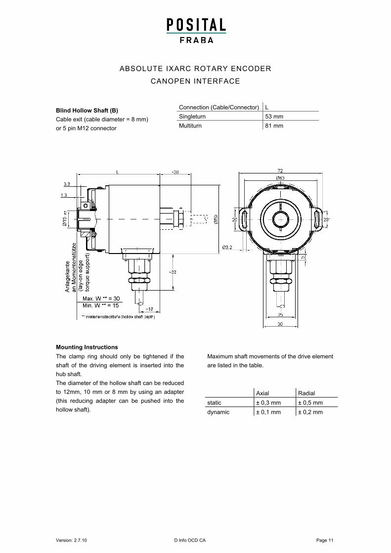
Blind Hollow Shaft (B)
Cable exit (cable diameter = 8 mm)
or 5 pin M12 connector
Mounting Instructions
The clamp ring should only be tightened if the
shaft of the driving element is inserted into the
hub shaft.
The diameter of the hollow shaft can be reduced
to 12mm, 10 mm or 8 mm by using an adapter
(this reducing adapter can be pushed into the
hollow shaft).
Maximum shaft movements of the drive element
are listed in the table.
Axial Radial
static ± 0,3 mm ± 0,5 mm
dynamic ± 0,1 mm ± 0,2 mm
Connection (Cable/Connector) L
Singleturn 53 mm
Multiturn 81 mm
Version: 2.7.10 E Info OCD CA Page 12
ABSOLUTE IXRAC ROTARY ENCODER
CANOPEN INTERFACE
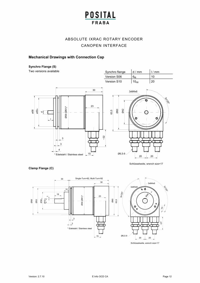
Mechanical Drawings with Connection Cap
Synchro Flange (S)
Two versions available
Clamp Flange (C)
d
~32
Ø60
Ø42
15
63,5
4
3
3
l
20 20
Single-Turn=82, Multi-Turn=92
Ø6,5-9
Schlüsselweite, wrench size=17
3xM4x6
3x1
20°
ø50
ø58
f7
Ø59 (
Ø61)* 23
30
* Edelstahl / Stainless steel
* Edelstahl / Stainless steel
3
10
18
20 20
Schlüsselweite, wrench size=17
15°
3x1
20°
3x120°
3xM4x6
Ø48
3xM3x6
63,5
Ø60
~27
Ø6,5-9
Single-Turn=82, Multi-Turn=92
Ø59 (
Ø61
)* 23
30
Ø58
Ø53
Ø36
15
1
30
Ø10
h8f7
3
Synchro flange d / mm l / mm
Version S06 6f6 10
Version S10 10h8 20
Version: 2.7.10 E Info OCD CA Page 13
ABSOLUTE IXARC ROTARY ENCODER
CANOPEN INTERFACE
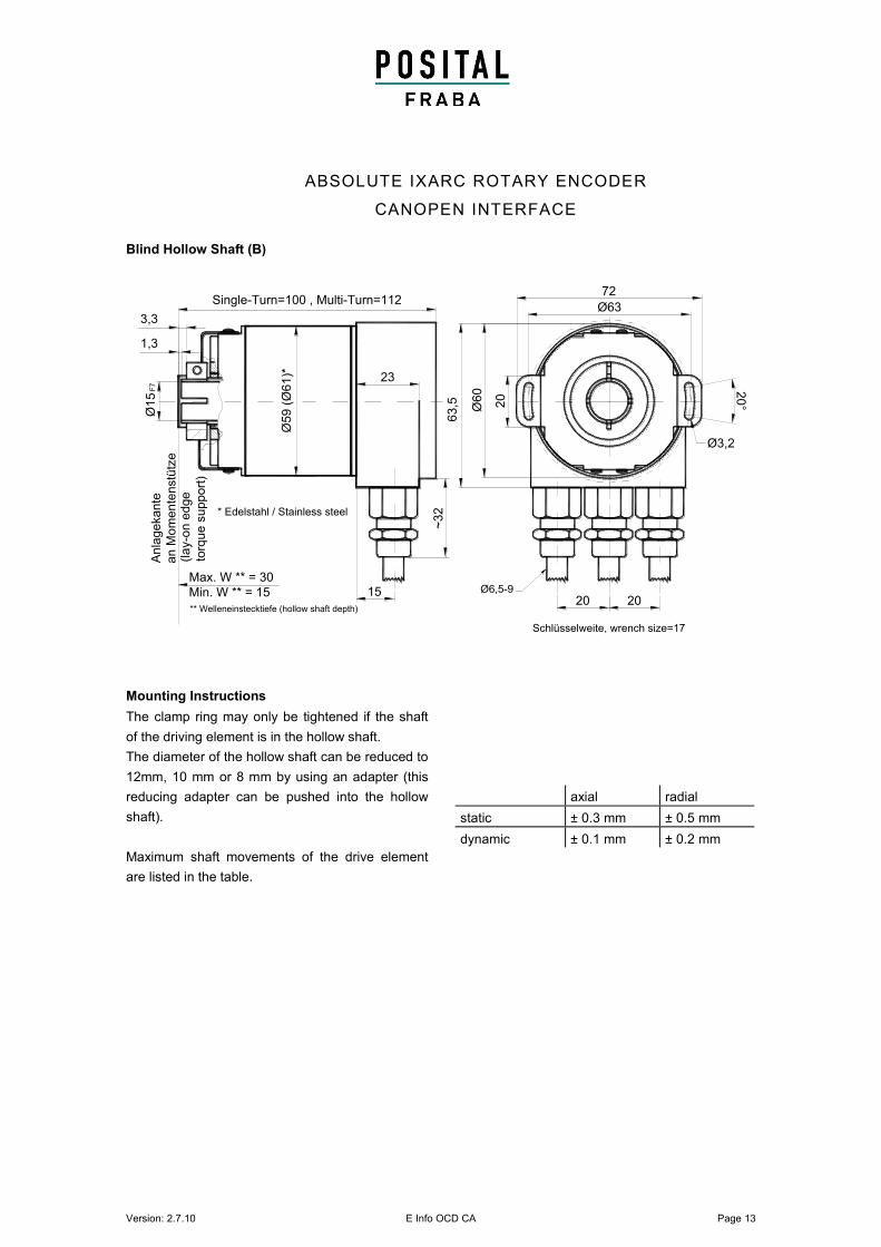
Blind Hollow Shaft (B)
Mounting Instructions
The clamp ring may only be tightened if the shaft
of the driving element is in the hollow shaft.
The diameter of the hollow shaft can be reduced to
12mm, 10 mm or 8 mm by using an adapter (this
reducing adapter can be pushed into the hollow
shaft).
Maximum shaft movements of the drive element
are listed in the table.
axial radial
static ± 0.3 mm ± 0.5 mm
dynamic ± 0.1 mm ± 0.2 mm
* Edelstahl / Stainless steel
20
°
Ø63
20
72Single-Turn=100 , Multi-Turn=112
1,3
3,3
Anla
gekante
an M
om
en
tenstü
tze
Ø1
5F
7
15
23
Ø59 (
Ø61)*
~32
Ø6,5-9
Schlüsselweite, wrench size=17
Ø3,26
3,5
20 20
Ø6
0
(lay-o
n e
dge
torq
ue s
upport
)
** Welleneinstecktiefe (hollow shaft depth)
Max. W ** = 30
Min. W ** = 15
Version: 2.7.10 E Info OCD CA Page 14
ABSOLUTE IXRAC ROTARY ENCODER
CANOPEN INTERFACE
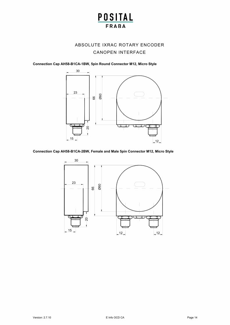
Connection Cap AH58-B1CA-1BW, 5pin Round Connector M12, Micro Style
Connection Cap AH58-B1CA-2BW, Female and Male 5pin Connector M12, Micro Style
Ø60
23
30
20
15
66
1212
Ø60
23
30
20
15
66
12
Version: 2.7.10 E Info OCD CA Page 15
ABSOLUTE IXARC ROTARY ENCODER
CANOPEN INTERFACE
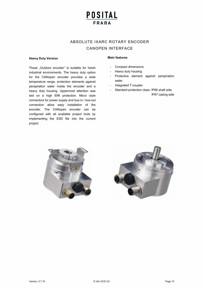
Heavy Duty Version
These „Outdoor encoder“ is suitable for harsh
industrial environments. The heavy duty option
for the CANopen encoder provides a wide
temperature range, protection elements against
perspiration water inside the encoder and a
heavy duty housing. Uppermost attention was
laid on a high EMI protection. Micro style
connectors for power supply and bus-in / bus-out
connection allow easy installation of the
encoder. The CANopen encoder can be
configured with all available project tools by
implementing the ESD file into the current
project.
Main features
- Compact dimensions
- Heavy duty housing
- Protective element against perspiration
water
- Integrated T-coupler
- Standard protection class: IP66 shaft side
IP67 casing side
Version: 2.7.10 E Info OCD CA Page 16
ABSOLUTE IXRAC ROTARY ENCODER
CANOPEN INTERFACE
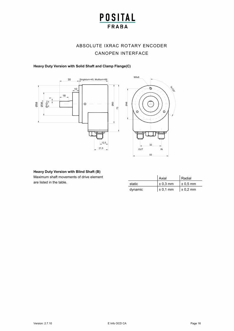
Heavy Duty Version with Solid Shaft and Clamp Flange(C)
Heavy Duty Version with Blind Shaft (B)
Maximum shaft movements of drive element
are listed in the table.
Axial Radial
static ± 0,3 mm ± 0,5 mm
dynamic ± 0,1 mm ± 0,2 mm
Ø60
23
3020
15
66
1212
Singleturn=45, Multiturn=69
Ø60
73
12,5
21,5
32
OUT IN
M4x6
3x120°
55
Ø48
1
Ø1
0h
8f7
Ø5
8
Ø3
6
10
18
30
Version: 2.7.10 E Info OCD CA Page 17
ABSOLUTE IXARC ROTARY ENCODER
CANOPEN INTERFACE
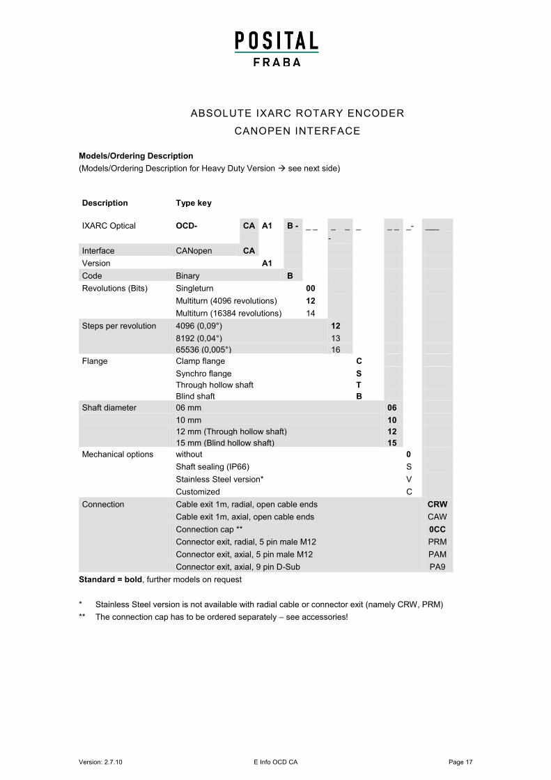
Models/Ordering Description
(Models/Ordering Description for Heavy Duty Version see next side)
Description Type key
IXARC Optical OCD- CA A1 B - _ _ _ _
-
_ _ _ _- ___
Interface CANopen CA
Version A1
Code Binary B
Revolutions (Bits) Singleturn 00
Multiturn (4096 revolutions) 12
Multiturn (16384 revolutions) 14
Steps per revolution 4096 (0,09°) 12
8192 (0,04°) 13
65536 (0,005°) 16
Flange Clamp flange C
Synchro flange S
Through hollow shaft T
Blind shaft B
Shaft diameter 06 mm 06
10 mm
10
12 mm (Through hollow shaft) 12
15 mm (Blind hollow shaft) 15
Mechanical options without 0
Shaft sealing (IP66) S
Stainless Steel version* V
Customized C
Connection Cable exit 1m, radial, open cable ends CRW
Cable exit 1m, axial, open cable ends CAW
Connection cap ** 0CC
Connector exit, radial, 5 pin male M12 PRM
Connector exit, axial, 5 pin male M12 PAM
Connector exit, axial, 9 pin D-Sub PA9
Standard = bold, further models on request
* Stainless Steel version is not available with radial cable or connector exit (namely CRW, PRM)
** The connection cap has to be ordered separately – see accessories!
Version: 2.7.10 E Info OCD CA Page 18
ABSOLUTE IXRAC ROTARY ENCODER
CANOPEN INTERFACE
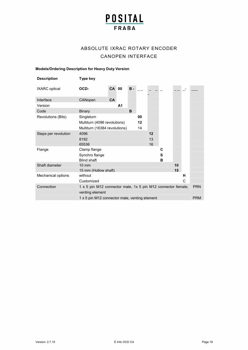
Models/Ordering Description for Heavy Duty Version
Description Type key
IXARC optical OCD- CA 00 B - _ _ _ _
-
_ _ _ _- ___
Interface CANopen CA
Version A1
Code Binary B
Revolutions (Bits) Singleturn 00
Multiturn (4096 revolutions) 12
Multiturn (16384 revolutions) 14
Steps per revolution 4096 12
8192 13
65536 16
Flange Clamp flange C
Synchro flange S
Blind shaft B
Shaft diameter 10 mm
10
15 mm (Hollow shaft) 15
Mechanical options without H
Customized C
Connection 1 x 5 pin M12 connector male, 1x 5 pin M12 connector female,
venting element
PRN
1 x 5 pin M12 connector male, venting element PRM
Version: 2.7.10 E Info OCD CA Page 19
ABSOLUTE IXARC ROTARY ENCODER
CANOPEN INTERFACE
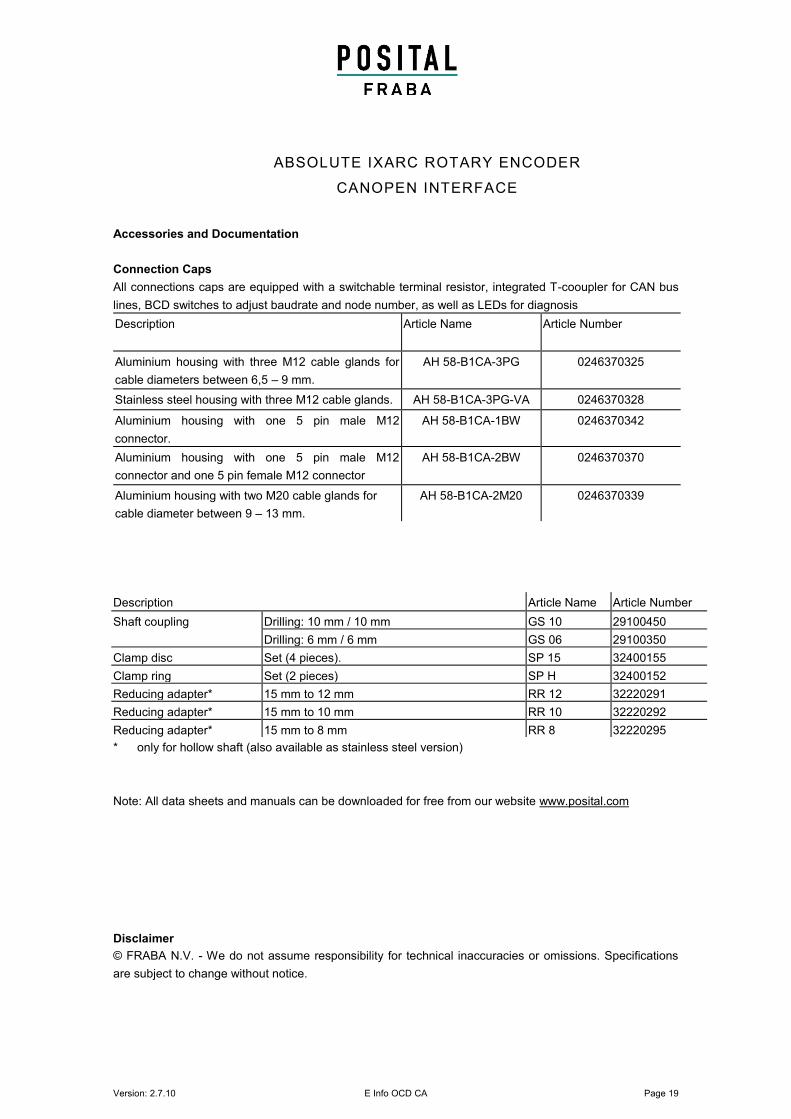
Accessories and Documentation
Connection Caps
All connections caps are equipped with a switchable terminal resistor, integrated T-cooupler for CAN bus
lines, BCD switches to adjust baudrate and node number, as well as LEDs for diagnosis
Description Article Name Article Number
Aluminium housing with three M12 cable glands for
cable diameters between 6,5 – 9 mm.
AH 58-B1CA-3PG 0246370325
Stainless steel housing with three M12 cable glands. AH 58-B1CA-3PG-VA 0246370328
Aluminium housing with one 5 pin male M12
connector.
AH 58-B1CA-1BW 0246370342
Aluminium housing with one 5 pin male M12
connector and one 5 pin female M12 connector
AH 58-B1CA-2BW 0246370370
Aluminium housing with two M20 cable glands for
cable diameter between 9 – 13 mm.
AH 58-B1CA-2M20 0246370339
* only for hollow shaft (also available as stainless steel version)
Note: All data sheets and manuals can be downloaded for free from our website www.posital.com
Disclaimer
© FRABA N.V. - We do not assume responsibility for technical inaccuracies or omissions. Specifications
are subject to change without notice.
Description Article Name Article Number
Shaft coupling Drilling: 10 mm / 10 mm GS 10 29100450
Drilling: 6 mm / 6 mm GS 06 29100350
Clamp disc Set (4 pieces). SP 15 32400155
Clamp ring Set (2 pieces) SP H 32400152
Reducing adapter* 15 mm to 12 mm RR 12 32220291
Reducing adapter* 15 mm to 10 mm RR 10 32220292
Reducing adapter* 15 mm to 8 mm RR 8 32220295