Embed Size (px)
Citation preview
1566 OPTICS LETTERS / Vol. 35, No. 10 / May 15, 2010
Absolute phase birefringence dispersion inpolarization-maintaining fiber or birefringentcrystal retrieved from a channeled spectrum
Petr Hlubina* and Dalibor CiprianDepartment of Physics, Technical University Ostrava, 17. listopadu 15, 708 33 Ostrava-Poruba, Czech Republic
*Corresponding author: [email protected]
Received February 5, 2010; revised March 22, 2010; accepted March 30, 2010;posted April 6, 2010 (Doc. ID 123892); published May 5, 2010
We report on a simple method for retrieving the wavelength dependence of the phase birefringence in apolarization-maintaining fiber or a birefringent crystal from a channeled spectrum. The method utilizes in-terference of polarized modes or waves resolved as the channeled spectrum and its processing by a windowedFourier transform to reconstruct precisely the phase as a function of wavelength. The ambiguity of the phaseis removed provided that we know both the approximative function for the birefringence dispersion and thelength of the fiber or the thickness of the crystal. The method is used in measuring the wavelength depen-dence of the phase birefringence in an elliptical-core fiber or in a quartz crystal in a range from500 to 900 nm. The dependences are compared with those resulting from the available data, and very goodagreement is confirmed. © 2010 Optical Society of America
OCIS codes: 060.2300, 060.2420, 120.3180, 260.1180, 260.1440, 260.2030.
Highly birefringent, polarization-maintaining fibers(PMFs) have attracted considerable interest for anumber of applications, including, e.g., polarization-sensitive optical devices and fiber-optic sensors ofvarious physical quantities employing interferomet-ric techniques. For these applications, it is importantto know the birefringence dispersion, i.e., the wave-length dependence of the phase and group birefrin-gence in the PMFs. Several methods have been devel-oped to measure the phase birefringence in PMFsover a wide spectral range. A wavelength scanningtechnique can be applied to either short [1] or long [2]fibers.
It is well known that scanning the wavelengthalone (a channeled spectrum) gives only a relativemeasure of the phase birefringence, and it inherentlymeasures the group birefringence. The absolutephase birefringence is obtained by both scanning thewavelength and absolutely measuring the birefrin-gence at one particular wavelength. To measure thisquantity, a precision electromagnetic modulationtechnique [1] or a lateral force method [3] applied inthe time [4] or wavelength [5] domain can be used.Similarly, the birefringence dispersion is of funda-mental importance for anisotropic materials used inoptical devices such as wave plates, compensators,retarders, and polarizers. Measurement of the phasebirefringence of a prescribed dispersion function canbe performed by spectral interferometric techniquesbased on either determining the positions of themaxima in a channeled spectrum [6] or fitting themeasured spectrum to the theoretical one [7].
In this Letter, a simple method for retrieving thewavelength dependence of the phase birefringence ina PMF of known length is presented. The technique,which is based on processing of a channeled spectrumto retrieve the phase function, utilizes the approxi-mative function of the phase birefringence disper-
sion. We extended the use of the technique for mea-0146-9592/10/101566-3/$15.00 ©
suring the phase birefringence in a quartz crystal ofknown thickness.
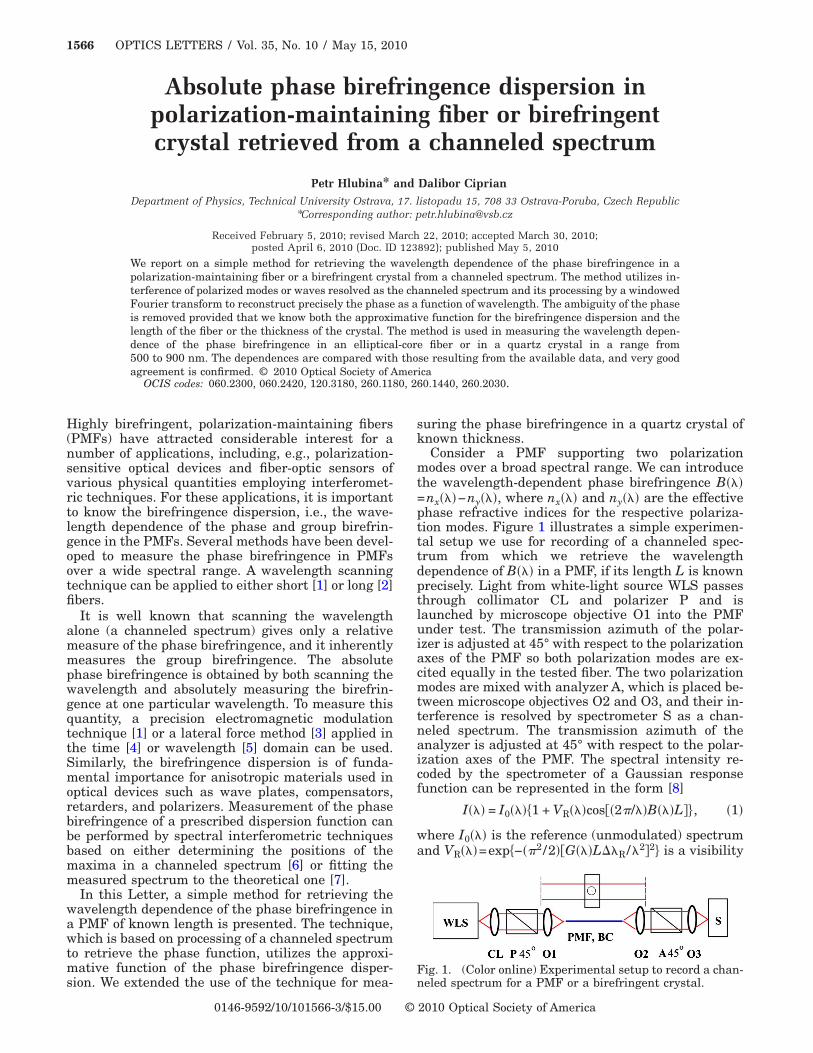
Consider a PMF supporting two polarizationmodes over a broad spectral range. We can introducethe wavelength-dependent phase birefringence B���=nx���−ny���, where nx��� and ny��� are the effectivephase refractive indices for the respective polariza-tion modes. Figure 1 illustrates a simple experimen-tal setup we use for recording of a channeled spec-trum from which we retrieve the wavelengthdependence of B��� in a PMF, if its length L is knownprecisely. Light from white-light source WLS passesthrough collimator CL and polarizer P and islaunched by microscope objective O1 into the PMFunder test. The transmission azimuth of the polar-izer is adjusted at 45° with respect to the polarizationaxes of the PMF so both polarization modes are ex-cited equally in the tested fiber. The two polarizationmodes are mixed with analyzer A, which is placed be-tween microscope objectives O2 and O3, and their in-terference is resolved by spectrometer S as a chan-neled spectrum. The transmission azimuth of theanalyzer is adjusted at 45° with respect to the polar-ization axes of the PMF. The spectral intensity re-coded by the spectrometer of a Gaussian responsefunction can be represented in the form [8]
I��� = I0����1 + VR���cos��2�/��B���L��, �1�
where I0��� is the reference (unmodulated) spectrumand VR���=exp�−��2 /2��G���L��R/�2�2� is a visibility
Fig. 1. (Color online) Experimental setup to record a chan-
neled spectrum for a PMF or a birefringent crystal.2010 Optical Society of America
May 15, 2010 / Vol. 35, No. 10 / OPTICS LETTERS 1567
term dependent on both the group birefringenceG���=−�2d�B��� /�� /d� and the width ��R of the spec-trometer response function. To resolve a channeledspectrum (spectral fringes) in a spectral range from�1 to �2, the fiber length must satisfy the conditionL��1
2 / �G��1���R�.From the recorded channeled spectrum, a relative
spectral phase �r��� can be retrieved with the ambi-guity of m2�, where m is an integer. To remove thephase ambiguity, we assume that the phase birefrin-gence dispersion is given by the relation [9]
B��� = A1�−4 + A2�−2 + A3 + A4�2 + A5�4, �2�
where Ai are the coefficients. The difference betweenthe retrieved phase function and the absolute phasefunction is the phase error function
e��� = �r��� + m2� − �2�/��B���L, �3�
which is a measure of the correct determination ofthe coefficients Ai and the interference order m. In anideal case e���=0.
The experimental setup used for measurement ofthe phase birefringence B��� in a PMF is shown sche-matically in Fig. 1, and it consists of a halogen lampHL-2000 (Ocean Optics), a collimating lens, micro-scope objectives �10� /0.30�, a Glan–Taylor calcitepolarizer and analyzer (Thorlabs), an elliptical-corePMF of length L= �356.5±0.5� mm, a fiber-optic spec-trometer S2000 (Ocean Optics), and other compo-nents. The PMF has a core made of GeO2-doped silicaglass �19.3 mol. %� and a cladding made of puresilica. The dimensions of the fiber elliptical core areapproximately 3.2 �m�1.2 �m. The spectrometer,with ��R�3 nm, has a spectral operation range from350 to 1000 nm.
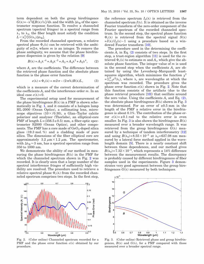
We demonstrate the ability of our method in mea-suring the phase birefringence B��� in the PMF forwhich the channeled spectrum shown in Fig. 2 wasrecorded. It is clearly seen that a large number of thespectral interference fringes of sufficiently high vis-ibility are resolved. The procedure used to retrieve arelative spectral phase �r��� from the recorded chan-neled spectrum comprises two steps. In the first step,
Fig. 2. (Color online) Channeled spectrum recorded for aPMF and the phase error function e��� obtained by our
procedure.the reference spectrum I0��� is retrieved from thechanneled spectrum I���. It is obtained as the inverseFourier transform of the zero-order component of theFourier spectrum of the recorded channeled spec-trum. In the second step, the spectral phase function�r��� is retrieved from the spectral signal S���=I��� /I0���−1 using a procedure based on a win-dowed Fourier transform [10].
The procedure used in the determining the coeffi-cients Ai in Eq. (2) consists of two steps. In the firststep, a trust-region algorithm [11] is used for the re-trieved �r��� to estimate m and Ai, which give the ab-solute phase function. The integer value of m is usedin the second step when the coefficients Ai are ob-tained by using the Levenberg–Marquardt least-squares algorithm, which minimizes the function �2
=�i=1N e2��i�, where �i are wavelengths at which the
spectrum was recorded. The procedure gives thephase error function e��� shown in Fig. 2. Note thatthis function consists of the artifacts (due to thephase retrieval procedure [10]) that oscillate aroundthe zero value. Using the coefficients Ai and Eq. (2),the absolute phase birefringence B��� shown in Fig. 3was determined. For an error of ±0.5 mm in thelength of the PMF a relative error in the birefrin-gence is about 0.1%. The contribution of the phase er-ror e���= ±0.1 rad to the relative error is evensmaller. In Fig. 3 is also shown the birefringence B���measured over a broader wavelength range. It wasretrieved from the group birefringence G��� mea-sured by a technique of tandem interferometry [12]and using B��0�=8.55�10−5 at �0=637.08 nm mea-sured by a lateral force method applied in the wave-length domain [5]. There is a nearly constant shiftbetween these dependences, and our method givesB��0�=7.32�10−5, which represents a 14% differencebetween the measurement results. The discrepancyis probably caused by different birefringences of fibersamples used in the experiments. Figure 3 demon-strates very good agreement between the group bire-fringences G��� measured by both techniques.
Fig. 3. (Color online) Retrieved phase and group birefrin-gences, B��� and G���, for a PMF compared with those
measured over a broader spectral range.
1568 OPTICS LETTERS / Vol. 35, No. 10 / May 15, 2010
We extended the use of our method in determiningthe phase birefringence Bf���=ne���−no��� in aquartz crystal, where ne��� and no��� are the phaserefractive indices of the extraordinary and ordinaryeigenwaves, respectively. Our setup was modified(see the upper part of Fig. 1), and for the crystal ofthickness t= �4010±1� �m and the orientation of theoptic axis shown in Fig. 1 we recorded the channeledspectrum shown in Fig. 4. It is clearly seen that alarge number of the spectral interference fringes ofsufficiently high visibility are resolved. The numberof the spectral fringes in the wavelength range from500 to 900 nm is given by the group path differenceGf���t in the crystal. Using the same procedure aspresented above, we retrieved the absolute birefrin-gence Bf��� shown in Fig. 5. For the phase errore����0.03 rad a relative error in the birefringence isabout 0.03%. The contribution of the thickness uncer-tainty to the relative error is even smaller. The samefigure shows the birefringence Bf��� resulting fromthe Sellmeier-like form of the dispersion relation forthe quartz crystal [8]. We clearly see that there isvery good agreement between these dependences,which have slightly different dispersion slopes.This is illustrated in Fig. 5 that shows the dispersionfunctions for the group birefringence Gf���=−�2d�Bf��� /�� /d�. The difference between them,which is in general dependent on the fitting function,is in part caused by the approximation (2) of thephase birefringence dispersion Bf��� we used.
In conclusion, a simple technique for retrieving theabsolute phase birefringence from a channeled spec-trum has been presented. It utilizes the approxima-tive function of the birefringence dispersion and thephase retrieval using a windowed Fourier transform.
Fig. 4. (Color online) Channeled spectrum recorded for abirefringent quartz and the phase error function e��� ob-
tained by our procedure.The feasibility of the technique has been demon-strated in measuring the phase birefringence in aPMF or in a quartz crystal. We confirmed very goodagreement with the available data. The use of thetechnique can be extended, e.g., for retrieving the dis-persion of the differential phase refractive index froma channeled spectrum originated from interference oftwo spatial modes guided in a fiber.
The research has been partially supported by theMinistry of Education, Youth and Sports of the CzechRepublic through grant MSM6198910016 and by theregional grant CZ.1.05/2.1.00/01.0040.
References
1. S. C. Rashleigh, Opt. Lett. 7, 294 (1982).2. M. G. Shlyagin, A. V. Khomenko, and D. Tentori, Opt.
Lett. 20, 869 (1995).3. K. Takada, J. Noda, and R. Ulrich, Appl. Opt. 24, 4387
(1985).4. W. J. Bock and W. Urbanczyk, Appl. Opt. 32, 5841
(1993).5. P. Hlubina and D. Ciprian, Opt. Express 15, 17019
(2007).6. M. Medhat and S. Y. El-Zaiat, Opt. Commun. 141, 145
(1997).7. H. Delbarre, M. Przygodzki, C. Tassou, and D. Boucher,
Appl. Phys. B 70, 45 (2000).8. P. Hlubina, D. Ciprian, and L. Knyblova, Opt. Com-
mun. 260, 535 (2006).9. M. Tsubokawa, N. Shibata, T. Higashi, and S. Seikai, J.
Opt. Soc. Am. A 4, 1895 (1987).10. P. Hlubina, J. Lunacek, D. Ciprian, and R. Chlebus,
Opt. Commun. 281, 2349 (2008).11. Curve Fitting Toolbox for Use with MATLAB (Math-
Works, 2000).12. P. Hlubina, D. Ciprian, and M. Kadulova, Meas. Sci.
Fig. 5. (Color online) Retrieved phase and group birefrin-gences, Bf��� and Gf���, for a birefringent quartz comparedwith those given by the dispersion relation.
Technol. 20, 025301 (2009).