Embed Size (px)
Citation preview

Abrasive Machining Processes
N. Sinha, Mechanical Engineering
Department, IIT Kanpur
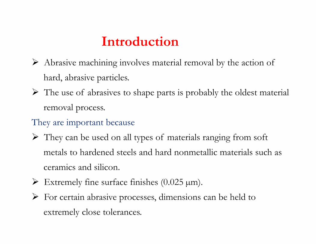
� Abrasive machining involves material removal by the action of
hard, abrasive particles.
� The use of abrasives to shape parts is probably the oldest material
removal process.
They are important because
Introduction
They are important because
� They can be used on all types of materials ranging from soft
metals to hardened steels and hard nonmetallic materials such as
ceramics and silicon.
� Extremely fine surface finishes (0.025 µm).
� For certain abrasive processes, dimensions can be held to
extremely close tolerances.

Types of Abrasive Machining Processes
� Grinding
� Honing
� Lapping
� Superfinishing
� Polishing� Polishing
� Buffing
� Abrasive water jet machining
� Ultrasonic machining

Difference between grinding and milling
� The abrasive grains in the wheel are much smaller and more
numerous than the teeth on a milling cutter.
� Cutting speeds in grinding are much higher than in milling.
� The abrasive grits in a grinding wheel are randomly oriented.� The abrasive grits in a grinding wheel are randomly oriented.
� A grinding wheel is self-sharpening.
Particles on becoming dull either fracture to create new
cutting edges or are pulled out of the surface of the wheel
to expose new grains.

Surface Grinding
Horizontal Surface Grinding
Vertical Surface Grinding

Surface Grinding
Horizontal Grinding Machine

Cylindrical Grinding
Two types of cylindrical grinding:
(a) external, and (b) internal

External Centerless Grinding

Grinding Wheel and Workpiece Interaction
�Grit-workpiece (forming chip)
�Chip-bond
�Chip-workpiece
�Bond-workpiece
� Except the grit-workpiece interaction, which is expected to
produce chip, the remaining three undesirably increase the total
grinding force and power requirement.
� Therefore, efforts should always be made to maximize grit-
workpiece interaction leading to chip formation and to
minimize the rest for best utilization of the available power.

Grinding Wheel Parameters
�Type of Abrasive material
�Grain size
�Wheel grade
�Wheel structure�Wheel structure
�Bonding material

Abrasive Materials
General Properties
Hardness, wear resistance, toughness, friability

Effective grit geometry due to material loading at tip
� Grit geometry may undergo substantial change due to mechanical or� Grit geometry may undergo substantial change due to mechanical or
chemical attrition leading to rounding or flattening of the sharp cutting
points.
� This happens when the work material has hard or abrasive constituent.
� A chip material adhered to the tip of the grit because of some chemical
affinity can also change the effective rake angle of the grit leading to high
grinding force, temperature and poor performance of the grinding wheel.

SiC and Ferrous Materials
� SiC abrasives are harder than friable Al2O3 but they are usually
inferior for grinding most ferrous materials.
� This is due to the dissociation of SiC to react with and adhere to
iron at elevated temperatures. (Affinity of silicon or carbon for the
workpiece)workpiece)
� Therefore, SiC tends to work better than Al2O3 on some ferrous
metals with excess carbon.
� Superiority of SiC on some cast irons is due to the presence of
small amounts of SiC as a normal constituent in the iron, which
would have a more drastic effect on the wear of the softer Al2O3.

Grain Size
� Grain size is expressed in terms of a SIEVE NUMBER, Sn which
corresponds to the number of openings per linear inch.
� The diameter of an abrasive grain is given by
� The larger the size of grains, more will be material removal, but
surface finish will be worse.
Sieve No. Type of Grain
10-24 Coarse
30-60 Medium
70-180 Fine
220-600 Very Fine

Grinding Wheel Structure
“Open” and “dense”
In what conditions
these structures be
provided?
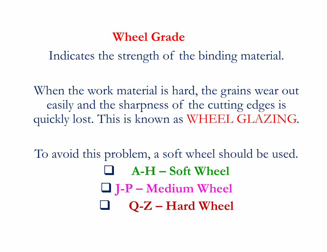
Wheel Grade
Indicates the strength of the binding material.
When the work material is hard, the grains wear out easily and the sharpness of the cutting edges is
quickly lost. This is known as WHEEL GLAZING.quickly lost. This is known as WHEEL GLAZING.
To avoid this problem, a soft wheel should be used.
� A-H – Soft Wheel
� J-P – Medium Wheel
� Q-Z – Hard Wheel

Bonding Materials
Vitrified Bond (V) – Strong and Rigid, commonly used.Vitrified Bond (V) – Strong and Rigid, commonly used.
Resinoid (B) – Provides shock absorption and elasticity.
They are strong enough.
Silicate (S) – Provides softness (grains dislodge quickly)
Shellac (E) – Used for making thin but strong wheels
possessing some elasticity.
Rubber Bonds (R) – For making flexible wheels.
Metallic Bond (M) – For diamond wheels only.

Bonding Materials
Vitrified Bond (V) – Strong and Rigid, commonly
used.
Resinoid (B) – Provides shock absorption and
elasticity. They are strong enough.
Silicate (S) – Provides softness (grains dislodge
quickly)
Shellac (E) – Used for making thin but strong
wheels possessing some elasticity.
Rubber Bonds (R) – For making flexible wheels.
Metallic Bond (M) – For diamond wheels only.

Grinding Wheel Specification
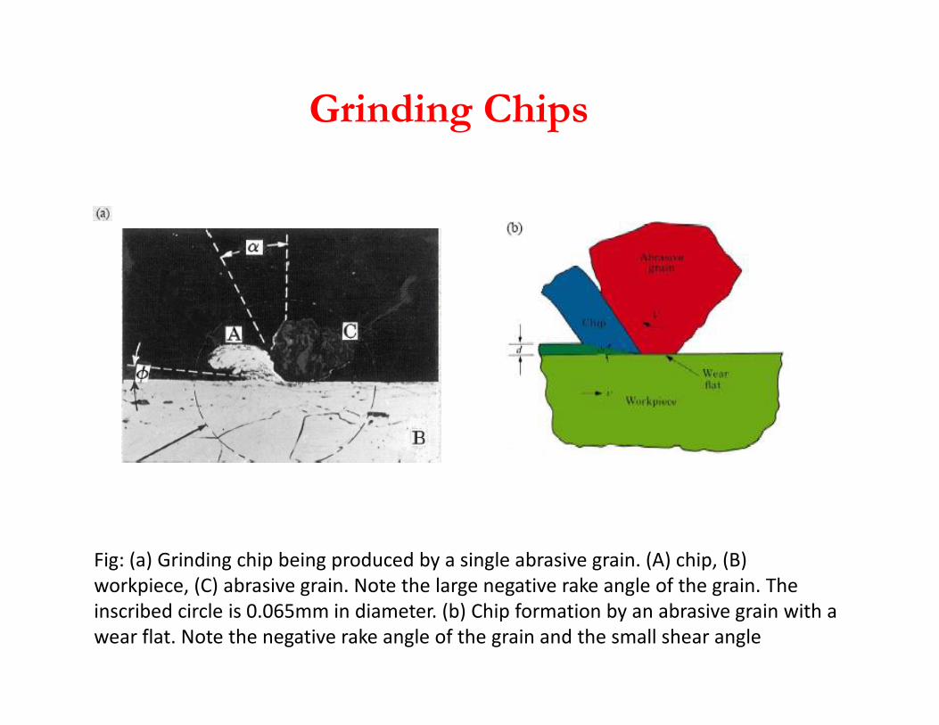
Grinding Chips
Fig: (a) Grinding chip being produced by a single abrasive grain. (A) chip, (B)
workpiece, (C) abrasive grain. Note the large negative rake angle of the grain. The
inscribed circle is 0.065mm in diameter. (b) Chip formation by an abrasive grain with a
wear flat. Note the negative rake angle of the grain and the small shear angle
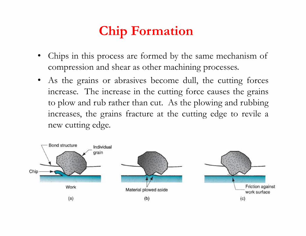
Chip Formation
• Chips in this process are formed by the same mechanism of
compression and shear as other machining processes.
• As the grains or abrasives become dull, the cutting forces
increase. The increase in the cutting force causes the grains
to plow and rub rather than cut. As the plowing and rubbing
increases, the grains fracture at the cutting edge to revile aincreases, the grains fracture at the cutting edge to revile a
new cutting edge.

Chip Formation
� The importance of the grit shape can be easily realized because it determinesthe grit geometry e.g. rake and clearance angle.
� The grits do not have definite geometry and the grit rake angle may vary from+45 to -60 or more.
� Grit with favorable geometry can produce chip in shear mode. However, gritshaving large negative rake angle or rounded cutting edge do not form chips butmay rub or make a groove by plowing leading to lateral flow of the workpiecematerial.

Effect of grinding velocity and rake angle on force
� A negative rake angle always leads to higher cutting force.
� The difference is narrowed at a high grinding velocity and the
grinding force becomes virtually independent of the rake angle.

Various Stages of Grinding with Grit Depth of Cut
At a small grit penetration only sliding of the grit occurs against the
workpiece. In this zone, rise of force with increase of grit penetration is
quite high.
With further increase of the grit penetration, grit starts ploughing causing
plastic flow of the material also associated with high grinding force.
With further increase of penetration, the grit start cutting and the rate of
rise of force with increase of grit depth of cut is much less than what can be
seen in the sliding and ploughing zone.
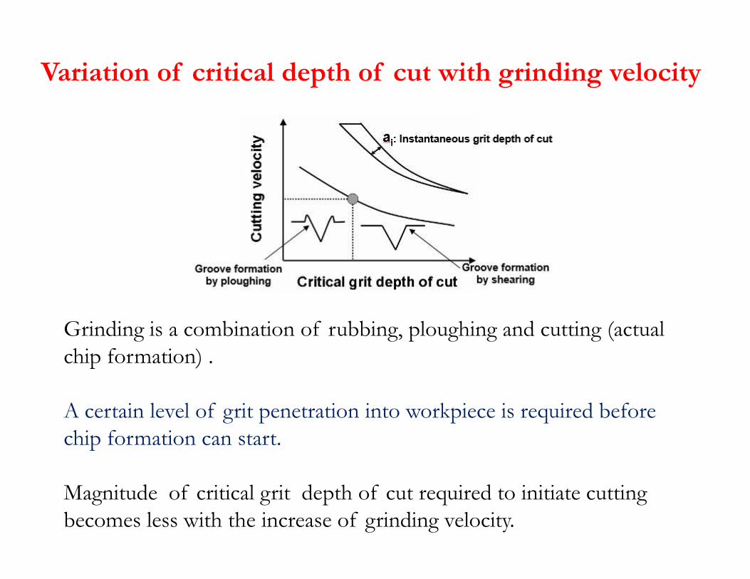
Variation of critical depth of cut with grinding velocity
Grinding is a combination of rubbing, ploughing and cutting (actual
chip formation) .
A certain level of grit penetration into workpiece is required before
chip formation can start.
Magnitude of critical grit depth of cut required to initiate cutting
becomes less with the increase of grinding velocity.

Determination of the Density of Active Grains
Backer, Marshall and Shaw method: the grinding wheel is rolled
over a glass plate covered with a layer of carbon black.
Peklenik and Opitz method: employs a thermocouple located at
the surface of the workpiece. As each active grain passes, a
thermocouple junction is formed between the wire and the thermocouple junction is formed between the wire and the
workpiece and a pulse is obtained from the high temperature
developed that can be counted using an oscilloscope.
Grisbrook method: the surface of the grinding wheel is viewed
on a projection microscope, and the number of cutting points
passing a line on the projection screen is counted as the wheel is
rotated a given amount.

Testing of Grinding Wheels
Strength of a bond: pass a sintered metal carbide or diamond
chisel over the wheel surface in such a way that it tears a layer of
grains from the bond.
The forces required to separate a layer of grains from the bond are
taken as a measure of the strength of the bond.
Hardness
a) Drill the wheel with a hard spade-type drill with a constant force.
The depth of penetration in a given time is a measure of wheel
hardness.
b) Use an air/abrasive jet to break the bond. The depth of
penetration of the jet erosion in a standard period of time is
used to determine equivalent wheel hardness.
c) Measure the resonant frequency of an isolated wheel after a
sharp blow with a rubber hammer and relate it to hardness.

Grinding Wheel Wear
Grain fracture: a portion of the grain breaks off, but the rest of
the grain remains bonded in the wheel.
Attritious wear: dulling of the individual grains, resulting in flat
spots and rounded edges.
Bond fracture: the individual grains are pulled out of the
bonding material.bonding material.

Grinding Wheel Wear
G = Volume of material removed
Volume of wheel wear
Vary greatly (2-200 or higher) depending on thetype of wheel, grinding fluid, and processparameters
Higher forces decrease the grinding ratio
(1): the grains are initially sharp, and wear is accelerated due to
grain fracture.
(2): characterized by attritious wear, with some grain and bond
fracture.
(3): the grains become dull and the amount of ploughing and
rubbing increases relative to cutting.