Embed Size (px)
Citation preview

BULUCUT-2
ABRASIVE CUTTER
BMS Bulut Makina Sanayi Ve Ticaret Ltd. Şti. İkitelli Organize Sanayi Bölgesi Dolapdere Sanayi Sitesi
Ada 4 No : 7-9 Başakşehir / İSTANBUL-TÜRKİYE Phone : +90 212 671 02 24 / 671 02 25 Fax : +90 212 671 02 26
web : www.bulutmak.com e-mail : [email protected]
OP
ER
AT
ION
AL
MA
NU
AL

1 DESCRIPTION ----------------------------------------------------------------------------------------------------------------------------- 3
2 TECHNICAL SPECIFICATIONS ------------------------------------------------------------------------------------------------------ 3
3 STANDART ACCESSORIES ------------------------------------------------------------------------------------------------------------ 3
4 UNPACKING ------------------------------------------------------------------------------------------------------------------------------- 7
5 INSTALLATION --------------------------------------------------------------------------------------------------------------------------- 7
6 PLUMBING --------------------------------------------------------------------------------------------------------------------------------- 7
7 CUTTER WHEEL LOCATING -------------------------------------------------------------------------------------------------------- 7
8 CUTTING FLUID MANUAL ------------------------------------------------------------------------------------------------------------ 7
8.1 FİRST TİME FİLLİNG OF RESERVOİR TANK ------------------------------------------------------------------------------------------------ 7 8.2 ADDİNG CUTTİNG FLUİD AFTER SOME PERİOD OF USAGE ------------------------------------------------------------------------------ 7 8.3 SAMPLE FİXİNG -------------------------------------------------------------------------------------------------------------------------------- 8 8.4 CUTTİNG OPERATİON ------------------------------------------------------------------------------------------------------------------------- 8
9 LED LIGHT SYSTEM -------------------------------------------------------------------------------------------------------------------- 8
10 PART LIST ---------------------------------------------------------------------------------------------------------------------------------- 8

1 DESCRIPTION Abrasive Cutter
Sturdy table model for sectioning Metals, Ceramic and mineral samples.
Corrosion resistance GRP cover with see - through hood.
Special Aluminum casted heavy robust base.
Easy use twin cam actuated vises for holding samples.
All inside parts made from stainless steel or chromium plated steel.
Splash proof during cutting.
Cooling by two high flow water jets to provide optimum cutting.
Cutting action provided by moving motor on specimen.
11 W light illuminator protected from water in specially isolated cover fixed inside the cover to obtain safe
and clear illumination on cutting area.
Separately mounted recirculation coolant tank with large drain.
57 ltr capacity coolant tank, suitable filtering part provided to filter the slugs formed during cutting.
2 TECHNICAL SPECIFICATIONS Machine dim’s 650x700 x1600 mm
Case dim’s inc. cooling system 1000x1000x1600 mm
Weight (net/gross) 130 / 200 kg
Motor 3 KW, AC
380 Volt, Three phase 2850 rpm
Cutting system Manual
Table dimensions T-slotted clamping table( 370 x 173 mm) (1 pcs)
Clamping devices Fast cam locking vises (2 pcs)
Cutting capacity 90 mm dia
Cutting wheel size 250 X 32 X 1,6 (1,5) mm
Coolant pump 380 Volt, Three phase , 0,12 KW
Coolant reservoir dim’s 600 x 400 x 300 mm,
57 ltr capacity
3 STANDART ACCESSORIES Abrasive cutter,
Recirculating cooling system
Two coolant circulation hoses and clips,
Arrow wrench and pin.
250 mm, 5 abrasive cutting wheels,
Cutting fluid (5lt)
Fast cam locking vise clamping devices (2 pcs)
TOP COVER SAFETY SWITCH (Top cover opens after 10 sec. when the cutting proses is done or machine has the energy) waiting time can be adjustable

EM
ER
GE
NC
Y
ELECTRIC PANEL
POWER
BASE OF CUTTER
SAFETY SWITCH
TOP COVER
CUTTING LEVER
SEE THROUGH HOOD
LEVELLING BOLT
COOLANT RESERVOIR TANK
FILTER
TOP COVER
WATER HOSE EXIT (COOLANT HOSE TO RESERVOIR)
RECIRCULATION PUMP
ST
AR
T
PU
MP
LA
MP
ST
OP
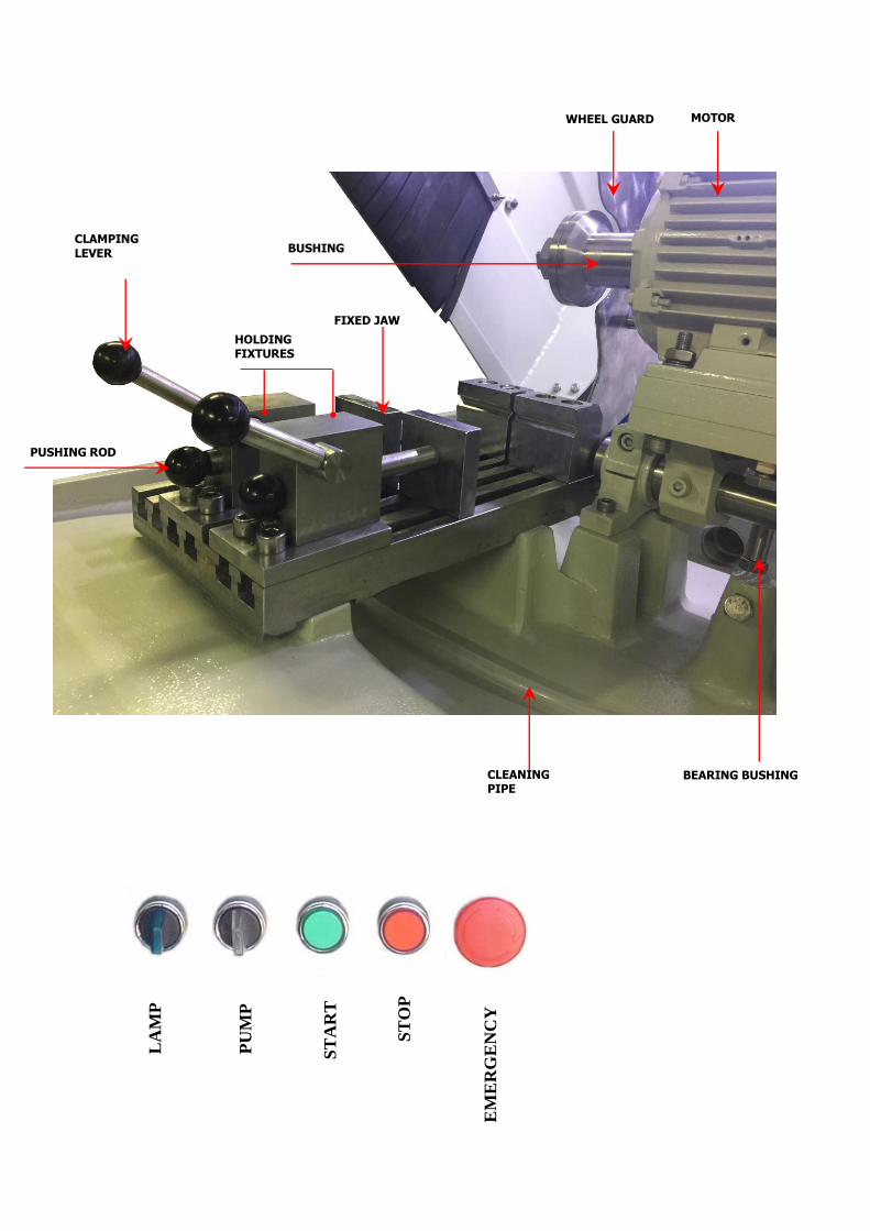
CLEANING PIPE
PUSHING ROD
MOTOR WHEEL GUARD
HOLDING FIXTURES
BUSHING
BEARING BUSHING
FIXED JAW
CLAMPING
LEVER
EM
ER
GE
NC
Y
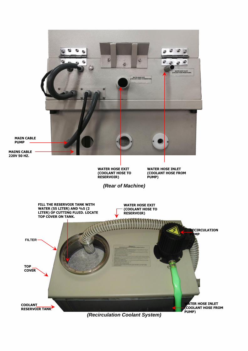
(Rear of Machine)
(Recirculation Coolant System)
WATER HOSE EXIT (COOLANT HOSE TO RESERVOIR)
WATER HOSE INLET (COOLANT HOSE FROM PUMP)
MAINS CABLE
220V 50 HZ.
MAIN CABLE PUMP
COOLANT RESERVOIR TANK
TOP COVER
RECIRCULATION PUMP
FILTER
FILL THE RESERVOIR TANK WITH WATER (55 LITER) AND %5 (2 LITER) OF CUTTING FLUID. LOCATE TOP COVER ON TANK.
WATER HOSE INLET (COOLANT HOSE FROM PUMP)
WATER HOSE EXIT (COOLANT HOSE TO RESERVOIR)

4 UNPACKING
Remove packing materials and lift out machine complete with baseboard. Remove 4 securing
bolts that secures machine to baseboard.
5 INSTALLATION Open cover. (01)
Remove the shipping strap from the cutting head and push the cutting lever (26) to the rear to raise the
cutting Wheel (18) as high as possible.
Install the cutter on suitable table and secure alignment by means of adjusting positions of 4 secure leveling
bolts. (03)
Plug to mains 380-400V (3 phase) power and check the turning position of cutter and ensure correct turning
if necessary.
6 PLUMBING
Locate recirculation pump on its table and bring it to the near of cutter.
Make recirculation pump electrical connections Connect 18 mm coolant supply hose to the rear of cutter and
tighten the hose clamp. Locate the other end to recirculation pump and tighten the hose clamp.
Connect the 40 mm dia coolant return hose to rear of cutter and clip the hose clamp. Locate other end of
hose on filter of reservoir tank
Fill the reservoir tank with water (55 liter) and %5 (3 liter) of cutting fluid. Locate top cover on tank.
Open the cover of cutter and press PUMP button and allow pump to run a few minutes. This procedure
ensures adequate mixing of coolant solution. (PUMP button is not used when the cover is closed.)
7 CUTTER WHEEL LOCATING Please pay attention while installing abrasive cutting wheel. Do not use wheel dia greater than 250 mm and
thickness 1,8 mm.
Raise cover (01) and remove the Wheel guard. (20) .Insert the arbor pin into hole of bushing (19) and using
36 mm wrench loosen the wing nut (16) (Bushing of motor spindle has left hand thread) and locate the
cutter.(18) wheel in position perfectly.
Make the same procedure to ensure tighten of wing nut as well. Never leave arbor pin inserted into hole of
bushing (19)
Make sure two faces of wheel and bushing clean.
8 CUTTING FLUID MANUAL
8.1 First Time Filling Of Reservoir Tank
- Obtain separate tank for mixing. (For example 25 ltr. plastic tank)
- Fill tank with water.(For example 20 ltr) Later ,add ,%5 CIMSTAR 506 cutting fluid ( or its compatible ) (
1 ltr for 20 ltr water )
- While adding, cutting fluid to water slowly, mix well
- Put this mixed fluid to reservoir tank.
8.2 Adding Cutting Fluid after Some Period of Usage
- In case of requirement of adding cutting fluid after first time filing, followings to be considered.
- Fill plastic tank with water. (For example 20 ltr.) Later, add %3 CIMSTAR 506 Cutting fluid (For 20 ltr
water 0.6 ltr cutting fluid.)
- While adding, cutting fluid to water slowly, mix well
4) - Put this mixed fluid to reservoir tank.
LEVELING BOLT

After each month of usage we recommend you to clean reservoir tank and add new cutting fluid as first time
filling.
8.3 Sample Fixing
Two wises positioned at our works for general purpose of cutting.
When required for larger samples, it can be necessary to reposition the wises nearer to the front of the
machine. For this purpose, loosen 4 bolts of fixing plate of holding fixture. Locate the sample on fixed jaw
(07) and push forward clamping jaw (08) against sample. Use a suitable pressure and push clamping lever
(13) tightly. Do not over clamp.
8.4 Cutting Operation
Be sure sample is clamped and jaws tighted well.
Close the cover. (The cutter will not operate unless the cover is completely closed)
Start cutting and pump motors by pressing START button. (Do not start motors when cutting lever is in
mid position and be sure cutting wheel is not touching the sample)
Check the flow of coolant and adjust the flow of water jets if required
Slowly feed the cutter wheel on sample by pulling cutting lever. (17)
To reach constants cutting range maintain pressure as required. (Excessive force may cause motor overload
and damage cutter wheel.)
When cutting procedure is completely finished, bring the cutting lever to its starting position.
Cutter wheel rotates for several seconds after pushing STOP button or opening cover. In case of
opening cover, please be sure cutter wheel completely stopped.
9 LED LIGHT SYSTEM
LED 24V DC, 8,4W /1 MT
10 PART LIST Part Nr Part name Part Nr Part name
1 cover 14 Pushing rod
2 Base of cutter 15 Vises
3 Leveling bolt 16 Wing nut
4 Fixing plate of vise section 17 Plate
5 Pin 18 Cutter wheel
6 Vise plate 19 Bushing
7 Fixed jaw 20 Wheel guard
8 Clamping jaw 21 Motor
9 Top plate of swiveling arm 22 Fixing bush
10 Swiveling bushing 23 Bearing housing
11 Holding fixture 24 Fixing plate of motor
12 Egzantric cam 25 Rotating spindle
13 Clamping lever 26 Cutting lever