Embed Size (px)
Citation preview

Reactive Power Conditioning The full power factor solution
ABB, DM, Power Protection – Laurent Maillefer, May 2014
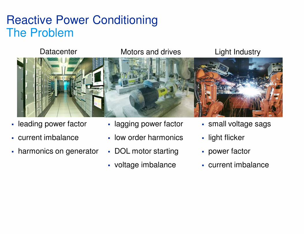
� leading power factor
� current imbalance
� harmonics on generator
Reactive Power Conditioning The Problem
Motors and drives Light Industry
� lagging power factor
� low order harmonics
� DOL motor starting
� voltage imbalance
� small voltage sags
� light flicker
� power factor
� current imbalance
Datacenter

Reactive Power ConditioningThe Problem
� Typical applications problems that can be fixed or mitigated by reactive power:
� Power factor correction with dynamic issues such as:
� Fluctuating reactive loads (Voltage problems)
� Welders, Cranes, hoists
� Unbalanced loads (Negative Sequence problems)
� 1 and 2 phase loads welders, saws, presses, pumps etc.
� Low order harmonics (Harmonics)
� 6 pulse AC motor drives and UPSs drawing 5th and 7th
harmonic current – power factor and generator
compatibility issues
� Leading power factor (Power Factor problems)
� Some IT server power supplies will draw significant
leading power factor which can be significant problem for
UPSs and generators in datacenters

100%
Reactive Current
Voltage
0
100%
Reactive Current
Voltage
0
100%
Reactive Current
Voltage
0
100%
Reactive Current
Voltage
0
Switched passive components SVC
STATCOMSmall STATCOM +
switched passive components
Reactive power solutionsOverview

Reactive power solutions1: Switched capacitor/inductor banks
The simplest solution is without any doubts a
combination of switched passive elements, i.e.
switched capacitors and inductors.
The figure to the left shows qualitatively the
reactive current versus connected voltage of
such a solution. The reactive current depends
linearly on the grid voltage and as a
consequence the reactive power changes with
the square of the grid voltage. Depending on
the amount of switched component branches,
the reactive current can only be altered in
more or less large steps. Due to the limited
switching time of capacitors, the dynamic
performance of this solution is reduced.
Furthermore, switching transients have to be
accepted with this solution as well as regular
maintenance of the breakers.

Reactive power solutions2: Static VAr Compensator (SVC)
Figure to the left shows the
reactive current versus
connected voltage of a widely
used reactive power
compensator: the SVC (Static
VAr Compensator). The SVC
combines thyristor switched
capacitors (TSC) with thyristor
controlled reactors (TCR). Doing
so, a smooth variation of
reactive power over the
complete installed power range
is possible.

Reactive power solutions3 & 4: Statcom
Figure to the left shows the reactive current versus connected voltage of a STATCOM. The performance is similar to a SVC, i.e. it performs smooth variation of reactive current across its operating range with high dynamics. It has some advantages when compared to the Static Var Compensator (SVC), e.g., current injection independent of the system voltage, faster control and less of a space requirement.
Another option is the combination of switched passive components with a small-sized STATCOM. This solution still includes disadvantages of switched passive components, e.g. switching transients and the need for regular maintenance of the breakers.
From an operator’s point of view, a solution for reactive power compensation without mechanically switched components is therefore preferred.

Advantages Disadvantages
Switched
Capacitor Bank
• Robust
• Reliable
• Q can only be controlled stepwise
• Q = f(U2), IQ = 0 @ U = 0
• Risk for resonances in grid
• Need to be switched
� resonances can be hit
� special breakers needed (re-strike)
� discharge time (zero-crossing
switching)
� Pre-insertion resistors (or reactors)
SVC • Continuous Q control
• High dynamics
• Established
technology
(for >30 years)
• Q = f(U2), IQ = 0 @ U = 0
• Space requirements
• Harmonics
Reactive power solutionsComparison
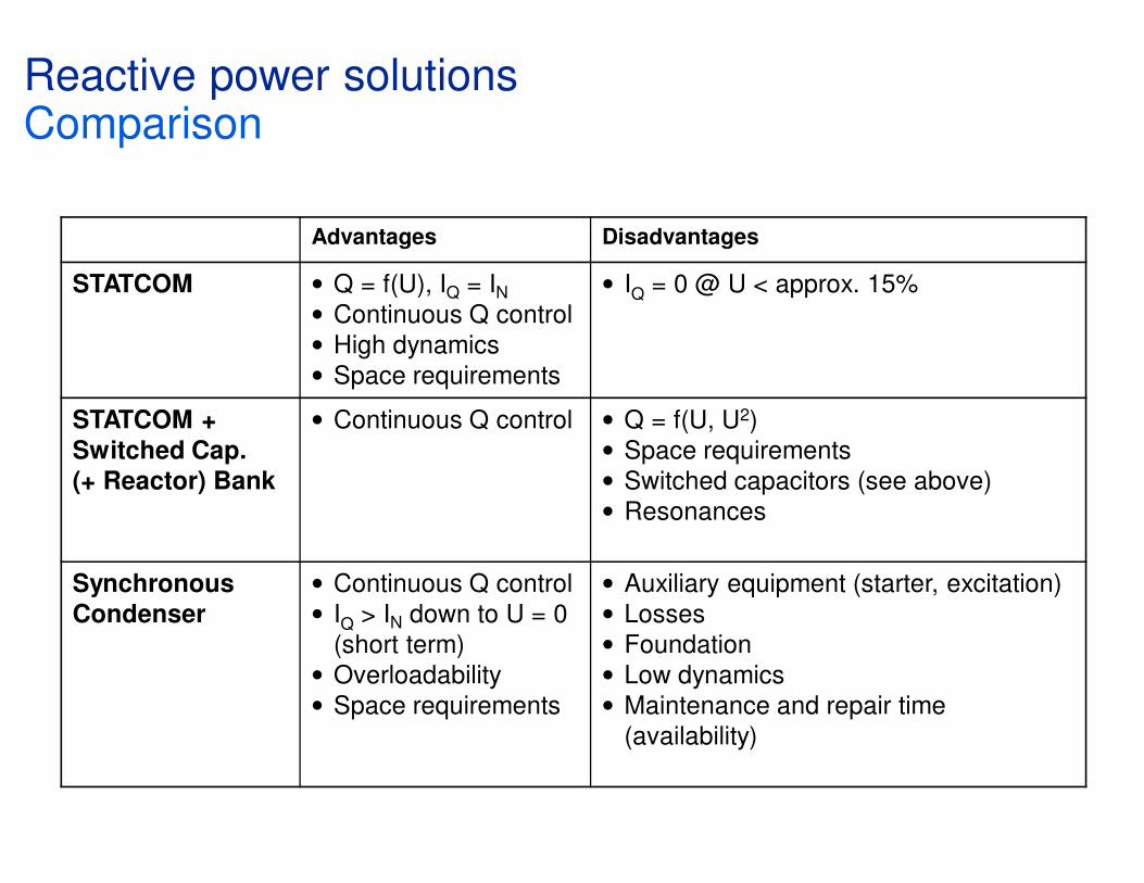
Advantages Disadvantages
STATCOM • Q = f(U), IQ = IN• Continuous Q control
• High dynamics
• Space requirements
• IQ = 0 @ U < approx. 15%
STATCOM +
Switched Cap.
(+ Reactor) Bank
• Continuous Q control • Q = f(U, U2)
• Space requirements
• Switched capacitors (see above)
• Resonances
Synchronous
Condenser
• Continuous Q control
• IQ > IN down to U = 0
(short term)
• Overloadability
• Space requirements
• Auxiliary equipment (starter, excitation)
• Losses
• Foundation
• Low dynamics
• Maintenance and repair time
(availability)
Reactive power solutionsComparison

© ABB GroupMay 9, 2014 | Slide 10
The Economic Benefit2MVA transformer example
What your meter is counting for your electricity bill is true RMS current!

Reactive Power ConditioningFeature/performance comparison of diff. solutions
TechnologyReactive Power
Conditioner
Active Harmonic
Filter
Switched Passive
Elements
Feature/Benefit
Speed
(VAr vs time)
Fast Fast Slow
Footprint Small Medium Large
Loss Low Medium Very Low
Harmonic
bandwidth
Medium High Low
Overload Often 200% Typically none None
Cost Medium High Low
Technology ComparisonRPC versus broadband active harmonic filters
� Broadband active harmonic filters are designed mitigating harmonics typically up to the 50th harmonic. To do this they need to switch their semiconductors at high switching speeds which results in additional loss and component de-rating.
� The Reactive Power Conditioner is optimised to correct just 50/60 Hz issues and low order harmonics (5th and 7th) which means lower switching frequencies can be used and as a result the product can be smaller, cheaper and have lower losses.
� For some applications, such as meeting certain standards, high order harmonics must be corrected and a broadband active filter is a good choice. Even in these cases it may be more economic to use a combination of products RPC for nominal and low order harmonics and with a small active harmonic filter for the high order harmonics.
� Most general fast VAr and difficult VAr applications do not require correction of high order harmonics.

Reactive Power Conditioning – How it works Reactive Power
� Reactive Power Conditioner = current source
� By injecting reactive current at fundamental frequency either leading or lagging power factor or small voltage problems can be corrected
� Injecting negative sequence current (different voltage vector rotation) in the load current allows imbalance to be corrected
� Injecting harmonic current equal but opposite to the load harmonic currents allows harmonics to be corrected
Load with High VAR
requirement
kW only on this side
Balanced current
Imbalanced current
RPC
RPC

What Size Do I Need?Power Factor
� How much Var’s are needed to correct the power factor?
� Data needed are power (real or apparent), the current power factor and the target power factor.
� S² = P² + Q²
� cos φ = P/S
� The system can be sized to provide 100% of the kVAr requirement
� Alternatively the Power Electronics can be sized for dynamic VArs(making use of the overload capability) and switched capacitors used for steady state or slow requirements.
Reactive power
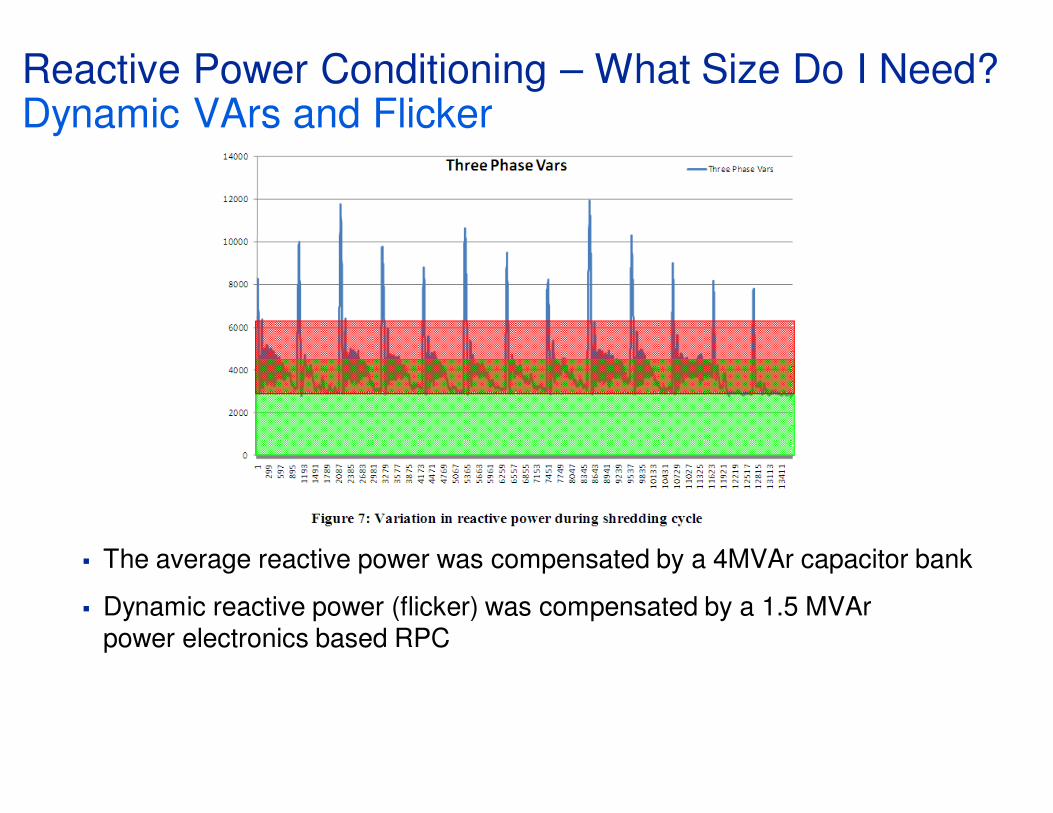
Reactive Power Conditioning – What Size Do I Need?Dynamic VArs and Flicker
� The average reactive power was compensated by a 4MVAr capacitor bank
� Dynamic reactive power (flicker) was compensated by a 1.5 MVArpower electronics based RPC

Reactive Power ConditioningIndustry Case Study: Polymide Film for FPC*
Problem
� Customer needed Uninterruptible Power Supply and PF>0.9
Solution
� A single conversion UPS 2100 kVA (30sec) and a 320 kVAr RPC on 415 Vac
Benefit
� Price
competitiveness
� PF>0.9
� Reduced 5th and
7th harmonics
� Small footprint
*Flexible Printed Circuits
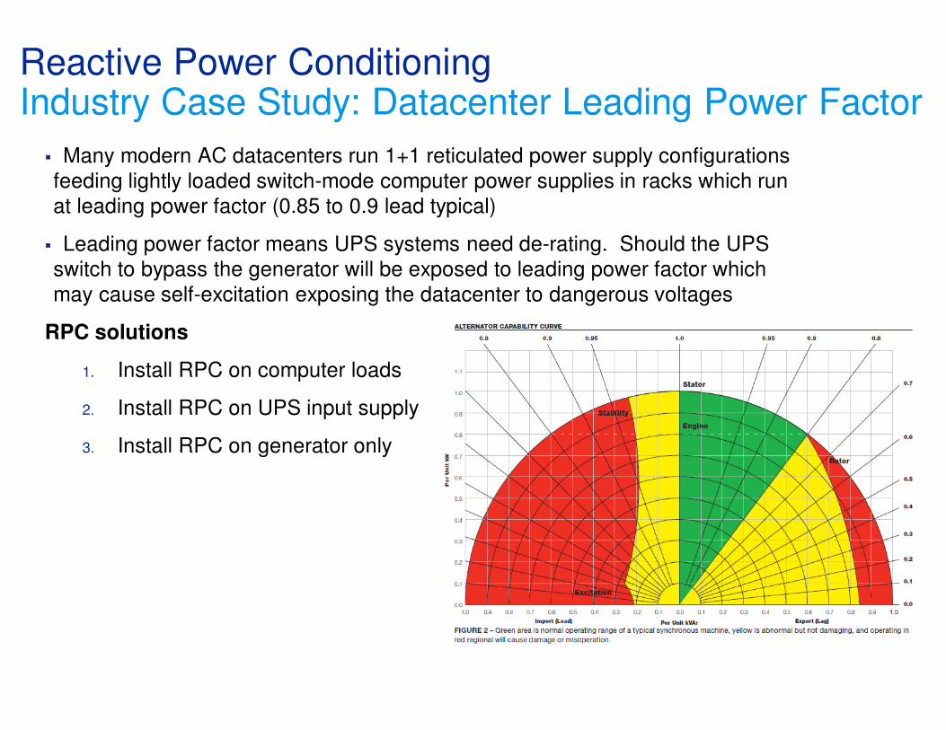
Reactive Power ConditioningIndustry Case Study: Datacenter Leading Power Factor
� Many modern AC datacenters run 1+1 reticulated power supply configurations
feeding lightly loaded switch-mode computer power supplies in racks which run
at leading power factor (0.85 to 0.9 lead typical)
� Leading power factor means UPS systems need de-rating. Should the UPS
switch to bypass the generator will be exposed to leading power factor which
may cause self-excitation exposing the datacenter to dangerous voltages
RPC solutions
1. Install RPC on computer loads
2. Install RPC on UPS input supply
3. Install RPC on generator only

Reactive Power ConditioningUnbalanced Current caused by load between 2 phases
Current waveformsCurrent waveforms
Current vectors

Reactive Power ConditioningNegative Sequence Current Injection by RPC
load current
current vectorscurrent vectors
grid current
current vectors
RPC current
+ =
+
+
+
=
=
=

� True power factor covers displacement and distortion.
� Power electronics based RPC systems provide a seamless solution to cover the bulk problem (displacement & low order harmonics) with the followings benefits:
� High Overload Capability
� Low loss
� Small footprint
� Hybrids can be build to create most economic solution
� Economic benefits can be easily calculated by true RMS current evaluation.
Reactive Power ConditioningConclusion