Embed Size (px)
Citation preview
1
LOW THRUST CIS-LUNAR TRANSFERS USING A 40 KW-CLASS SOLAR ELECTRIC PROPULSION SPACECRAFT
Melissa L. McGuire,* Laura M. Burke,† Steven L. McCarty,‡ Kurt J. Hack,§ Ryan J. Whitley,** Diane C. Davis,†† and Cesar Ocampo‡‡
This paper captures trajectory analysis of a representative low thrust, high power Solar Electric Propulsion (SEP) vehicle to move a mass around cislunar space in the range of 20 to 40 kW power to the Electric Propulsion (EP) system. These cislunar transfers depart from a selected Near Rectilinear Halo Orbit (NRHO) and target other cislunar orbits. The NRHO cannot be characterized in the classical two-body dynamics more familiar in the human spaceflight community, and the use of low thrust orbit transfers provides unique analysis challenges. Among the target orbit destinations documented in this paper are trans-fers between a Southern and Northern NRHO, transfers between the NRHO and a Distant Retrograde Orbit (DRO) and a transfer between the NRHO and two different Earth Moon Lagrange Point 2 (EML2) Halo orbits. Because many different NRHOs and EML2 halo orbits exist, simplifying assumptions rely on previous analysis of orbits that meet current abort and communication requirements for human mission planning.1 Investigation is done into the sensitivities of these low thrust transfers to EP system power. Additionally, the impact of the Thrust to Weight ratio of these low thrust SEP systems and the ability to transit between these unique orbits are investigated.
INTRODUCTION
To further human exploration beyond Low Earth Orbit (LEO), NASA has conducted multiple studies into orbits that could be useful in conducting the next steps of human missions in cislunar space. These studies have shown that orbits about the Moon can be used for both lunar focused missions and as a staging point for future human missions traveling deeper into our solar system. Recent NASA studies into human exploration of Mars have assumed the assembly, departure and return of the crewed in-space propulsion transport vehicle from a cislunar orbit with close proximity to the Moon. One candidate orbit the Near Rectilinear Halo Orbit (NRHO), a member of the Earth-Moon halo orbit family, has found much focus in these staging orbit studies.2 The NRHOs, which are characterized by long orbital periods and close passes over the Moon, have been under study as the node location to assemble deep space vehicles for lunar and deep space human mission architectures. All of these activities in the various lunar orbit studies assume the
*Lead Mission Design Engineer, Mission Architecture and Analysis Branch, NASA Glenn Research Center, 21000 Brookpark Road, Cleveland, Ohio 44135. [email protected]. †Aerospace Engineer, Mission Architecture and Analysis Branch, NASA Glenn Research Center, 21000 Brookpark Road, Cleve-land, Ohio 44135. [email protected]. ‡Aerospace Engineer, Mission Architecture and Analysis Branch, NASA Glenn Research Center, 21000 Brookpark Road, Cleve-land, Ohio 44135. [email protected] §§Lead Mission and Systems Analyst, Mission Architecture and Analysis Branch, NASA Glenn Research Center, 21000 Brookpark Road, Cleveland, Ohio 44135, [email protected]. **Aerospace Engineer, Exploration Mission Planning Office, NASA JSC, Houston, Texas 77058, [email protected] ††Principal Systems Engineer, a.i. solutions, Inc., 2224 Bay Area Blvd, Houston Texas 77058, [email protected] ‡‡Senior Analyst, Odyssey Space Research, 1120 NASA Parkway, Suite 505, Houston, Texas 77058.
AAS 17-583
https://ntrs.nasa.gov/search.jsp?R=20170009215 2018-05-28T09:31:58+00:00Z
2
use of low thrust in-space propulsion systems to provide both main propulsion, attitude control and station-keeping maneuvers.
NASA recently announced a Deep Space Gateway (DSG)3 as part of its architecture path to the explo-ration of deep space beyond Low Earth Orbit (LEO). For this analysis, it is assumed that the DSG will be assembled over time in an NRHO and will be used to gain experience during lunar missions to prepare for longer-duration deep space missions progressively farther from Earth. Missions in the lunar vicinity will span multiple phases of NASA’s concepts to build a sustainable infrastructure that could last multiple dec-ades and support missions of increasing complexity. As presented recently by NASA’s office of Human Exploration, an element like the DSG could be composed of a high-power Solar Electric Propulsion (SEP) stage, a habitat and a logistics module at a minimum. The use of an SEP stage offers lunar centric human missions the ability to perform transits starting in the NRHO and inserting into other cislunar destinations. This paper presents the initial trajectory design and analysis of utilizing a 40 kW SEP system to perform some representative cislunar transfers of a conceptual orbiting stack mass to and from an NRHO.
This paper documents the low thrust trajectory analysis of using this conceptual 40 kW class SEP stage in cislunar space. This analysis included modeling the trajectory of the SEP stage being delivered to its initial staging cislunar orbit, and modeling trajectories using this SEP stage to push a notional stack mass from the initial staging cislunar orbit to alternate cislunar orbit types.
DEEP SPACE GATEWAY
In March of 2017, NASA announced its conceptual next steps for exploration of destinations beyond LEO. In order to move toward these next steps, the first phase of this exploration about the Moon will involve the building of a Deep Space Gateway. The DSG is envisioned as a jumping off point for explora-tions further away from Earth and eventually to Mars.
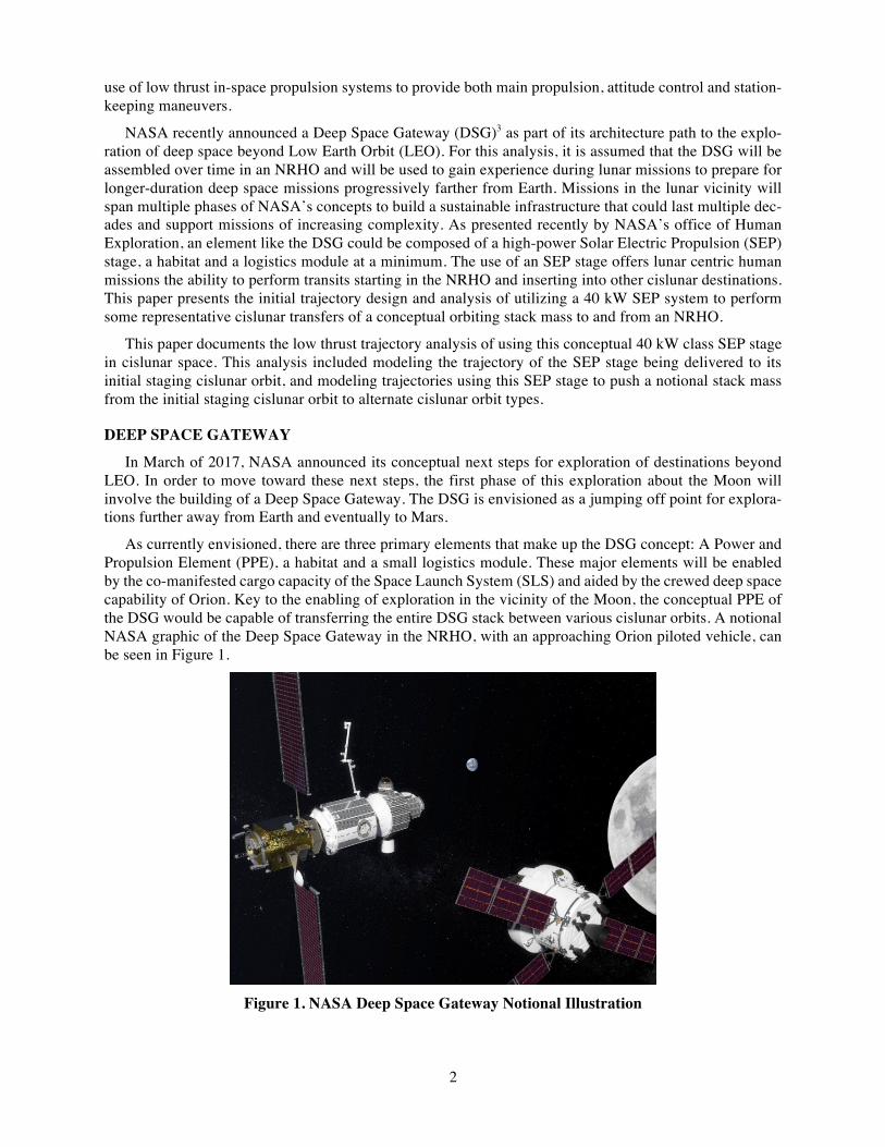
As currently envisioned, there are three primary elements that make up the DSG concept: A Power and Propulsion Element (PPE), a habitat and a small logistics module. These major elements will be enabled by the co-manifested cargo capacity of the Space Launch System (SLS) and aided by the crewed deep space capability of Orion. Key to the enabling of exploration in the vicinity of the Moon, the conceptual PPE of the DSG would be capable of transferring the entire DSG stack between various cislunar orbits. A notional NASA graphic of the Deep Space Gateway in the NRHO, with an approaching Orion piloted vehicle, can be seen in Figure 1.
Figure 1. NASA Deep Space Gateway Notional Illustration
3
POWER AND PROPULSION ELEMENT (PPE)
As currently being considered, the first element of the Deep Space Gateway is referred to as the Power and Propulsion Element (PPE). As envisioned, the PPE, a high-power solar electric propulsion stage, is responsible for providing power to the rest of the DSG elements as well as providing attitude control, orbit maintenance and primary propulsion to perform transfers between orbits in cislunar space. For the purpose of this preliminary analysis, it is assumed that the PPE technology is similar to that which had been planned for the recently cancelled Asteroid Redirect Robotic Mission (ARRM).4 The focus of ARRM was to capture a roughly 4 to 10 m asteroidal mass and return it to an orbit in cislunar space where crewed missions would be able to visit the asteroid to conduct scientific missions. The power and propulsion systems of the Asteroid Redirect Vehicle (ARV) consisted of high power solar arrays and advanced Hall thrusters5. Specifically, it is assumed that the power and propulsion system of the PPE consists of the same high power solar arrays, with a capability of providing on the order of 40 kW available to the Electric Propulsion (EP) system and magnetically shielded Hall Effect electric thruster strings. The power system will be capable of providing power to the main EP prolusion system and to the rest of the DSG stack elements and the EP system will be capable of providing main propulsion and attitude control and orbital maintenance maneuvers.
Ion Propulsion System Assumptions
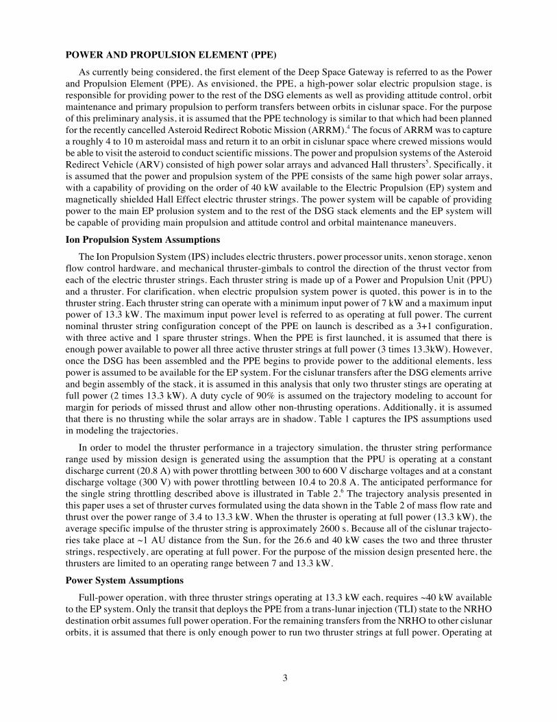
The Ion Propulsion System (IPS) includes electric thrusters, power processor units, xenon storage, xenon flow control hardware, and mechanical thruster-gimbals to control the direction of the thrust vector from each of the electric thruster strings. Each thruster string is made up of a Power and Propulsion Unit (PPU) and a thruster. For clarification, when electric propulsion system power is quoted, this power is in to the thruster string. Each thruster string can operate with a minimum input power of 7 kW and a maximum input power of 13.3 kW. The maximum input power level is referred to as operating at full power. The current nominal thruster string configuration concept of the PPE on launch is described as a 3+1 configuration, with three active and 1 spare thruster strings. When the PPE is first launched, it is assumed that there is enough power available to power all three active thruster strings at full power (3 times 13.3kW). However, once the DSG has been assembled and the PPE begins to provide power to the additional elements, less power is assumed to be available for the EP system. For the cislunar transfers after the DSG elements arrive and begin assembly of the stack, it is assumed in this analysis that only two thruster stings are operating at full power (2 times 13.3 kW). A duty cycle of 90% is assumed on the trajectory modeling to account for margin for periods of missed thrust and allow other non-thrusting operations. Additionally, it is assumed that there is no thrusting while the solar arrays are in shadow. Table 1 captures the IPS assumptions used in modeling the trajectories.
In order to model the thruster performance in a trajectory simulation, the thruster string performance range used by mission design is generated using the assumption that the PPU is operating at a constant discharge current (20.8 A) with power throttling between 300 to 600 V discharge voltages and at a constant discharge voltage (300 V) with power throttling between 10.4 to 20.8 A. The anticipated performance for the single string throttling described above is illustrated in Table 2.6 The trajectory analysis presented in this paper uses a set of thruster curves formulated using the data shown in the Table 2 of mass flow rate and thrust over the power range of 3.4 to 13.3 kW. When the thruster is operating at full power (13.3 kW), the average specific impulse of the thruster string is approximately 2600 s. Because all of the cislunar trajecto-ries take place at ~1 AU distance from the Sun, for the 26.6 and 40 kW cases the two and three thruster strings, respectively, are operating at full power. For the purpose of the mission design presented here, the thrusters are limited to an operating range between 7 and 13.3 kW.
Power System Assumptions
Full-power operation, with three thruster strings operating at 13.3 kW each, requires ~40 kW available to the EP system. Only the transit that deploys the PPE from a trans-lunar injection (TLI) state to the NRHO destination orbit assumes full power operation. For the remaining transfers from the NRHO to other cislunar orbits, it is assumed that there is only enough power to run two thruster strings at full power. Operating at
4
13.3 kW each, the two thruster strings require 26.6 kW available for the EP system. The assumptions for the power available to the EP system of the PPE and the power curve used for trajectory modeling, as a function of distance to the Sun, are shown in Table 3. For this trajectory, a conservative 1/R2 (where R is the spacecraft solar range) model is assumed.
Table 1. Ion Propulsion System Assumptions Mission parameter Value
Duty cycle (majority cruise phases) 90%
Number of thruster-PPU strings for insertion to NRHO 3+1
Number of thruster-PPU strings for all other orbit transfers 2+2
Minimum input power per thruster-PPU string 7 kW
Maximum input power per thruster-PPU string 13.3 kW
Table 2. EP String Performance EP string total input power (kW) Discharge voltage (V) Thrust (mN) Mass flow rate (mg/s) System efficiency
13.3 600 589 22.9 0.57
11.1 500 519 22.0 0.55
8.9 400 462 22.1 0.54
6.7 300 386 21.7 0.52
3.4 200 200 11.9 0.49
Table 3. Power System Assumptions Mission parameter Value
Solar array power curve 1/R2
EOL power to the PPU for NRHO insertion at 1AU 40 kW
EOL power to the PPU for NRHO transfers 1AU 26.6 kW
TRAJECTORY MODELING ASSUMPTIONS
The trajectories documented in this paper are modeled using the high-fidelity trajectory tool, Coperni-cus.7 Copernicus development started at the University of Texas at Austin and currently continues at John-son Space Center (JSC).8 Copernicus is a generalized spacecraft trajectory design and optimization tool, capable of designing low thrust and impulsive trajectory problems. Copernicus is an n-body tool and is considered high fidelity. The solutions presented in this paper are fully integrated finite-burn trajectories using the DE430 ephemeris model with point masses for the Earth and Moon. Solar gravity and radiation pressure have not been modeled at this time.
For the cislunar orbit transfer analysis, it is assumed that the DSG total stack wet mass, once all of the elements are assembled, is ~ 24,500 kg. This includes the PPE, the habitat and the logistics module. All of the analysis presented in this paper assumes the stack is uncrewed during all of the orbit transfers. Therefore, for this analysis, the PPE does not push a stack that would include the mass of a visiting Orion spacecraft.
The cislunar orbit in which the DSG is assumed to be assembled and from which all of the cislunar orbit transfers presented in this paper depart is a Near Rectilinear Halo Orbit (NRHO) mentioned previously. Details about the selected NRHO and NRHO families will be presented in a later section.
The total transit times for all of the analysis presented includes coast and thrust arcs. For each of the cislunar transfers, there are long coasts and long thrust arcs. All data presented are the one-way transfers
5
starting at a reference NRHO with a perilune radius of 3,233 km and a 9:2 lunar synodic resonant period and reaching a series of destination cislunar orbits. For round trip missions to and from this NRHO, an approximation of the total trip time and total DV could be estimated by doubling the values of the one-way transfers. All trajectories presented are the minimum propellant solutions.
PPE Delivery to NRHO
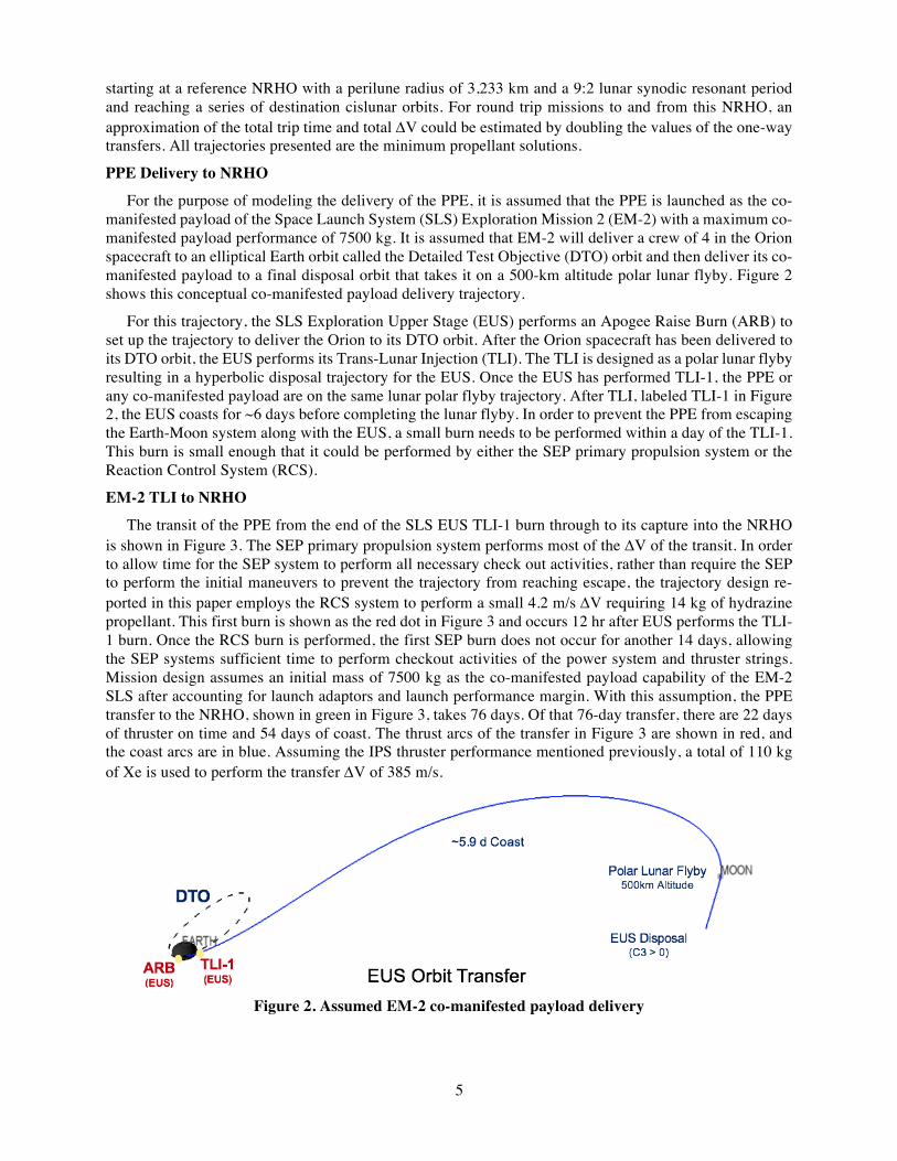
For the purpose of modeling the delivery of the PPE, it is assumed that the PPE is launched as the co-manifested payload of the Space Launch System (SLS) Exploration Mission 2 (EM-2) with a maximum co-manifested payload performance of 7500 kg. It is assumed that EM-2 will deliver a crew of 4 in the Orion spacecraft to an elliptical Earth orbit called the Detailed Test Objective (DTO) orbit and then deliver its co-manifested payload to a final disposal orbit that takes it on a 500-km altitude polar lunar flyby. Figure 2 shows this conceptual co-manifested payload delivery trajectory.
For this trajectory, the SLS Exploration Upper Stage (EUS) performs an Apogee Raise Burn (ARB) to set up the trajectory to deliver the Orion to its DTO orbit. After the Orion spacecraft has been delivered to its DTO orbit, the EUS performs its Trans-Lunar Injection (TLI). The TLI is designed as a polar lunar flyby resulting in a hyperbolic disposal trajectory for the EUS. Once the EUS has performed TLI-1, the PPE or any co-manifested payload are on the same lunar polar flyby trajectory. After TLI, labeled TLI-1 in Figure 2, the EUS coasts for ~6 days before completing the lunar flyby. In order to prevent the PPE from escaping the Earth-Moon system along with the EUS, a small burn needs to be performed within a day of the TLI-1. This burn is small enough that it could be performed by either the SEP primary propulsion system or the Reaction Control System (RCS).
EM-2 TLI to NRHO
The transit of the PPE from the end of the SLS EUS TLI-1 burn through to its capture into the NRHO is shown in Figure 3. The SEP primary propulsion system performs most of the DV of the transit. In order to allow time for the SEP system to perform all necessary check out activities, rather than require the SEP to perform the initial maneuvers to prevent the trajectory from reaching escape, the trajectory design re-ported in this paper employs the RCS system to perform a small 4.2 m/s DV requiring 14 kg of hydrazine propellant. This first burn is shown as the red dot in Figure 3 and occurs 12 hr after EUS performs the TLI-1 burn. Once the RCS burn is performed, the first SEP burn does not occur for another 14 days, allowing the SEP systems sufficient time to perform checkout activities of the power system and thruster strings. Mission design assumes an initial mass of 7500 kg as the co-manifested payload capability of the EM-2 SLS after accounting for launch adaptors and launch performance margin. With this assumption, the PPE transfer to the NRHO, shown in green in Figure 3, takes 76 days. Of that 76-day transfer, there are 22 days of thruster on time and 54 days of coast. The thrust arcs of the transfer in Figure 3 are shown in red, and the coast arcs are in blue. Assuming the IPS thruster performance mentioned previously, a total of 110 kg of Xe is used to perform the transfer DV of 385 m/s.
Figure 2. Assumed EM-2 co-manifested payload delivery

6
Figure 3. PPE low thrust transfer from EM-2 TLI to NRHO
NRHO Reference Orbit Details
The reference destination orbit for the PPE in cislunar space is the Near Rectilinear Halo Orbit (NRHO). This NRHO is the reference orbit where the PPE awaits the arrival of the rest of the elements for the DSG stack. It is from this NRHO that all of the cislunar transfers documented in this paper originate and return.
NRHOs are a subset of the halo families of orbits in the vicinity of the collinear libration points.9 In the Earth-Moon system, the L1 and L2 halo families evolve out of the Earth-Moon plane, with NRHOs ap-proaching the Moon. For this analysis, the initial reference orbit for DSG assembly is an L2 Southern 9:2 lunar synodic resonant NRHO shown in Figure 4. It is characterized by a perilune radius of about 3,233 km and an orbital period of 6.7 days.10 The 9:2 lunar synodic resonant NRHO is selected as the DSG orbit based on favorable transfer characteristics as well as the ability to avoid lengthy eclipses by the Earth. This NRHO exhibits nearly-stable behavior, and station-keeping algorithms enable long-term stays for either crewed or un-crewed assets.11
Figure 6 shows the southern family of halo orbits which can be calculated about the Earth Moon L2 point. In the graphics, the Moon and the L2 point are shown and the Earth is not shown off to the left of the image. The 9:2 resonant NRHO used as the target orbit in which the DSG will be assembled and from which all of the orbit transfers will start, is shown as the white orbit with a low periapse about the north pole of the Moon in Figure 6. This NRHO is considered a southern L2 halo orbit because its perilune is over the Moon’s North Pole and it spends most of its orbit above the Moon’s South Pole. The L1 and L2 Northern and southern NRHOs appear in Figure 5 where the southern NRHOs spend most of their orbit about the Moon’s South Pole and the Northern NRHOs spend most of their orbit about the Moon’s North Pole.
One of the cislunar transfers under consideration involves transferring the DSG from the L2 NRHO southern (NRHO S) to the L2 NRHO Northern (NRHO N). These two NRHOs under consideration for one of the cislunar orbit transfers are shown in the center of the halo families in Figure 5 highlighted in white.
For each departure and arrival to NRHO, an optimally phased 9:2 NRHO is constructed by targeting a partial state in a Moon-centered Earth-Moon rotating frame and optimizing the free components to achieve zero X- and Z-velocity at the Y-axis crossing and the desired period. The targeted velocity is zero in the X- and Z-direction and free in the Y-direction, where X is along the Earth-Moon line and Z is parallel to the angular momentum vector of the system. The targeted position is free in the X-direction, zero in the Y-direction, and 3,233 km in the Z-direction. This strategy provides a straightforward way to generate a rep-resentative 9:2 NRHO at any required epoch in the ephemeris model. It should be noted, however, that this does not necessarily generate a long-term stable NRHO.

7
Figure 4. 9:2 resonant Southern NRHO
Figure 5. L1 and L2 Northern
and Southern NRHOs
Figure 6. L2 Southern Halo Family
Distant Retrograde Orbit (DRO) Target Orbit
One target orbit considered for as a potential target orbit for DSG transfers in cislunar space presented in this paper is a Distant Retrograde Orbit (DRO) with a radius of about 70,000 km. Considered long term stable on the order of >100 years with only small variations in its orbit over time, this orbit was also con-sidered for use as the final storage orbit of the asteroid returned to Earth in ARRM analysis.12 The DRO exists because of three body effects, in this case between the Earth and Moon. For each arrival to the DRO destination orbit, an optimally phased 70,000 km DRO is constructed by targeting a partial state in a Moon-centered Earth-Moon rotating frame and optimizing the free components to achieve zero X-velocity at the Y-axis crossing with an appropriate period. The targeted velocity is zero in the X- and Z-direction and free in the Y-direction, where X is along the Earth-Moon line and Z is parallel to the angular momentum vector of the system. The targeted position is -70,000 km in the X-direction and zero in the Y- and Z-direction. This strategy provides a straightforward way to generate a representative DRO at any required epoch in the ephemeris model.

8
EML2 Target Orbits
Two additional target orbits considered as cislunar transfer destinations are more traditional halo orbits about the Earth-Moon Lagrange Point L2. There are several families of EML2 halo orbits with varying shapes and DV and propellant cost at which the transfer from the NRHO S can be performed. The first halo orbit targeted in this analysis, referred to as Option 1 Flat Halo with a period of 15 days, is described as “flat” with respect to the Earth’s equatorial plane. The flat L2 halo was chosen as one extreme of the halo family for its slightly better accessibility from Earth based assets. The second halo orbit, referred to as Option 2 Halo, is in the middle of the reference starting 9:2 NRHO and the Option 1 flat L2 halo with a period of 13.8 days and has both in plane and out plane components which thus enables constant line of sight to the Earth. Because they are unstable orbits, these halos have stable and unstable manifold trajecto-ries that can provide low-cost transfers to Earth, other orbits in cislunar space, and beyond.
TRANSFERS BETWEEN CISLUNAR ORBITS
The cislunar transfer trajectory types presented in this paper are summarized in Table 4. All transfers start from the southern NRHO (NRHO S) described previously and shown in Figure 5 and use low thrust propulsion to transfer to the final destination orbit. The transfer destinations are NRHO N, DRO, and the two EML2 options described previously. All of these cislunar orbit transfers utilize two thruster strings operating at full power, with a total EP system power of 26.6 kW to push a total stack mass of 24,500 kg. All are one way transfers that begin in the NRHO S and end at the target destination. The thruster on-time and coast times, as well as total Xe necessary to perform the DV for each transfer, are presented in Table 4. It can be observed from the data that the transfer from the NRHO S to the Option 2 flat halo with the requires the least amount of Xe mass to perform the least amount of transfer DV. The transfer from the NRHO S to the flat EML2 halo requires the most Xe to perform the most amount of transfer DV.
Other transfers between the NRHO and target orbits may exist that have a lower DV requirement but also have a longer transfer time. Some of these transfers have been identified over the course of developing the selected transfer trajectories detailed the following sections. However, since DV as well as shorter trip times are of importance for this particular study, minimum DV solutions with reasonable time-of-flight transfer trajectories are selected.
NRHO S to NRHO N
The first cislunar transfer designed is from an NRHO S to an NRHO N. Taking a total of 72 days, with 23 days of thrust and 49 days of coast, this trajectory is shown in Figure 7. Using 2 thruster strings operating at the full 26.6 kW total EP system power, 81 kg of Xe are needed to perform the 87 m/s total mission DV for this transfer. In Figure 7, the final NRHO is colored in red and the initial NRHO is colored in green. The use of 3 thruster strings operating at full power (~ 40 kW) to perform this transfer requires the same amount of total trip time, but requires slightly less Xe to perform a slightly lower amount of DV. Power sensitivity of these cislunar orbit transfers is presented later in this paper.
Table 4. Trajectory details for cislunar transfers
One-way transfer 26.6 kW power to the EP system
Trip time (days)
Thruster on time (days)
Coast time (days)
Xe used (kg)
DV (m/s)
NRHO S to NRHO N 72 23 49 81 87
NRHO to DRO 151 28 123 98 105
NRHO to EML2 (Option 1 flat halo) 214 16 198 56 60
NRHO to EML2 (Option 2 halo) 56 18 38 62 66

9
Figure 7. Transfer from NRHO south to NRHO north
Table 5. Trajectory details for NRHO-S to NRHO-N cislunar transfer Mission segment duration (days)
NRHO-S departure burn 1st coast 2nd burn 2nd coast 3rd burn 4th coast NRHO-N capture burn
5.6 10.2 7.3 4.9 5.5 34.2 4.9
With an initial SEP burn lasting 5.6 days, the PPE stack departs the Southern NRHO and leaves the
immediate lunar vicinity. During its transit around the Earth the PPE performs two additional SEP burns before a 4.9 day SEP burn to capture into the Northern NRHO. The longest burn arc for this orbital transfer is 7.3 days. A summary of the burn and coast durations during this transfer is provided in Table 5.
NRHO to DRO
The second cislunar transfer designed is from the 9:2 NRHO to the DRO described earlier. Taking a total of 151 days, with 28 days of thrust and 123 days of coast, this trajectory is shown in Figure 8. Using 2 thruster strings operating at the full 26.6 kW total EP system power, 98 kg of Xe are needed to perform the 105 m/s total mission DV for this transfer. The NRHO starting orbit is colored in green, and the final DRO is shown in red.
With an initial SEP burn lasting 3.4 days, the PPE stack departs the NRHO and leaves the immediate lunar vicinity. During its transit around the Earth the PPE performs three additional SEP burns. A majority of the time spent away from the Moon is spent coasting. Upon return to near lunar vicinity, the trajectory performs two close lunar flybys before a 10.9 day SEP burn to capture into the DRO. A summary of the burn and coast durations during this transfer is provided in Table 6.

10
Figure 8. NRHO to DRO one-way representative transfer orbit
Table 6. Trajectory details for NRHO to DRO cislunar transfer Mission segment duration (days)
NRHO departure burn 1st coast 2nd burn 2nd coast 3rd burn 3rd coast 4th burn 4th coast DRO capture burn
3.4 16.6 0.15 24.6 11.5 72.9 2.3 9.1 10.9
NRHO to EML2
The third cislunar transfer type designed is from the 9:2 NRHO to an EML2 halo orbit. Trajectories between the NRHO and the two different EML2 Halo orbits, a flat halo and a more traditional halo orbit described earlier are presented in this section.
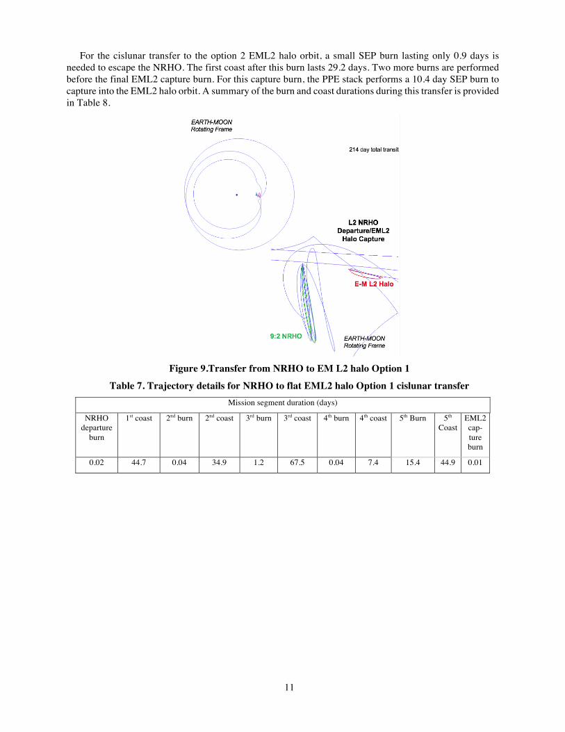
The first cislunar transfer to the Option 1 flat halo takes a total of 214 days, with 16 days of thrust and 198 days of coast. This trajectory is shown in Figure 9. Using 2 thruster strings operating at their full power of 26.6 kW total EP system power, 56 kg of Xe are needed to perform the 60 m/s total mission DV for this transfer. The NRHO starting orbit is colored in green, and the final EM-L2 halo orbit is shown in red.
For the cislunar transfer to the flat EML2 halo orbit, a small SEP burn lasting only 0.02 days is needed to escape the NRHO. Due to the flatness of this halo orbit with respect to the Earth-Moon rotating frame, in order to align itself for a minimum DV capture, the PPE stack makes several transits around the Earth prior to the EML2 capture burn. To accomplish this re-alignment the PPE stack performs five SEP burns prior to a 0.01 day SEP burn to capture into the EML2 halo orbit. A summary of the burn and coast durations during this transfer is provided in Table 7.
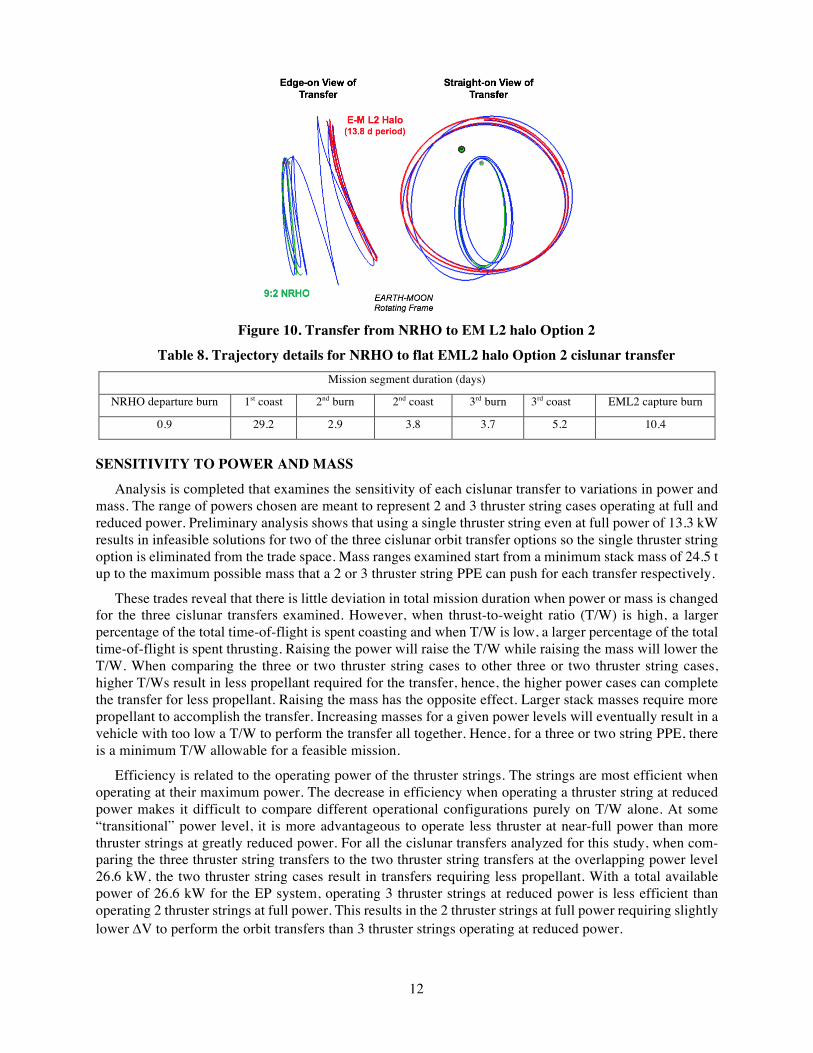
The second cislunar transfer to the Option 2 halo takes a total of 56 days, with 18 days of thrust and 38 days of coast. This trajectory is shown in Figure 10. Using 2 thruster strings operating at their full power of 26.6 kW total EP system power, 62 kg of Xe are needed to perform the 66 m/s total mission DV for this transfer. The NRHO starting orbit is colored in green, and the final EM-L2 halo Option 2 orbit is shown in red.
11
For the cislunar transfer to the option 2 EML2 halo orbit, a small SEP burn lasting only 0.9 days is needed to escape the NRHO. The first coast after this burn lasts 29.2 days. Two more burns are performed before the final EML2 capture burn. For this capture burn, the PPE stack performs a 10.4 day SEP burn to capture into the EML2 halo orbit. A summary of the burn and coast durations during this transfer is provided in Table 8.
Figure 9.Transfer from NRHO to EM L2 halo Option 1
Table 7. Trajectory details for NRHO to flat EML2 halo Option 1 cislunar transfer Mission segment duration (days)
NRHO departure
burn
1st coast 2nd burn 2nd coast 3rd burn 3rd coast 4th burn 4th coast 5th Burn 5th Coast
EML2 cap-ture burn
0.02 44.7 0.04 34.9 1.2 67.5 0.04 7.4 15.4 44.9 0.01
12
Figure 10. Transfer from NRHO to EM L2 halo Option 2
Table 8. Trajectory details for NRHO to flat EML2 halo Option 2 cislunar transfer Mission segment duration (days)
NRHO departure burn 1st coast 2nd burn 2nd coast 3rd burn 3rd coast EML2 capture burn
0.9 29.2 2.9 3.8 3.7 5.2 10.4
SENSITIVITY TO POWER AND MASS
Analysis is completed that examines the sensitivity of each cislunar transfer to variations in power and mass. The range of powers chosen are meant to represent 2 and 3 thruster string cases operating at full and reduced power. Preliminary analysis shows that using a single thruster string even at full power of 13.3 kW results in infeasible solutions for two of the three cislunar orbit transfer options so the single thruster string option is eliminated from the trade space. Mass ranges examined start from a minimum stack mass of 24.5 t up to the maximum possible mass that a 2 or 3 thruster string PPE can push for each transfer respectively.
These trades reveal that there is little deviation in total mission duration when power or mass is changed for the three cislunar transfers examined. However, when thrust-to-weight ratio (T/W) is high, a larger percentage of the total time-of-flight is spent coasting and when T/W is low, a larger percentage of the total time-of-flight is spent thrusting. Raising the power will raise the T/W while raising the mass will lower the T/W. When comparing the three or two thruster string cases to other three or two thruster string cases, higher T/Ws result in less propellant required for the transfer, hence, the higher power cases can complete the transfer for less propellant. Raising the mass has the opposite effect. Larger stack masses require more propellant to accomplish the transfer. Increasing masses for a given power levels will eventually result in a vehicle with too low a T/W to perform the transfer all together. Hence, for a three or two string PPE, there is a minimum T/W allowable for a feasible mission.
Efficiency is related to the operating power of the thruster strings. The strings are most efficient when operating at their maximum power. The decrease in efficiency when operating a thruster string at reduced power makes it difficult to compare different operational configurations purely on T/W alone. At some “transitional” power level, it is more advantageous to operate less thruster at near-full power than more thruster strings at greatly reduced power. For all the cislunar transfers analyzed for this study, when com-paring the three thruster string transfers to the two thruster string transfers at the overlapping power level 26.6 kW, the two thruster string cases result in transfers requiring less propellant. With a total available power of 26.6 kW for the EP system, operating 3 thruster strings at reduced power is less efficient than operating 2 thruster strings at full power. This results in the 2 thruster strings at full power requiring slightly lower DV to perform the orbit transfers than 3 thruster strings operating at reduced power.

13
These trades encompass a wide range of thrust-to-weights for a 2 or 3 thruster string PPE. By fitting a polynomial to the thrust-to-weight vs. propellant or DV data it is easy to predict if a power and mass com-bination for the PPE and stack will lead to feasible or infeasible missions. Likewise, if the power available at 1 AU, the number of operational thruster strings, and the stack mass are known, then the curve fit poly-nomial can provide a good approximation for the propellant required for the cislunar transfer.
The results and observations for the power and mass trades for each of the cislunar transfers are provided in the following sections.
NRHO S to NRHO N
Plots of power vs. propellant for 2 and 3 thruster strings for 24.5, 30, and 50 t stack masses are provided in Figures 11 and 12, respectively. The power range under consideration ranged from 26.6 to 40 kW to match the 2 and 3 thruster string cases. Separate total propellant mass curves are shown for the different stack mass assumptions.
Figure 11. Power vs. propellant (3 strings) S-L2 to N-L2 transfer
Figure 12. Power vs. propellant (2 strings) S-L2 to N-L2 transfer
For stack masses between 24.5 and 50 t, the NRHO S to NRHO N transfers all require between 80 to 160 kg of propellant depending on mass, power, and number of thruster strings.
At 26.6 kW, the two-thruster string case produces a transfer that requires less propellant than the three-thruster string case. However, the limitation of the two-thruster string configuration is that it cannot push the larger stack masses that the three-thruster string configuration can. A 50 t stack (approximately the mass
14
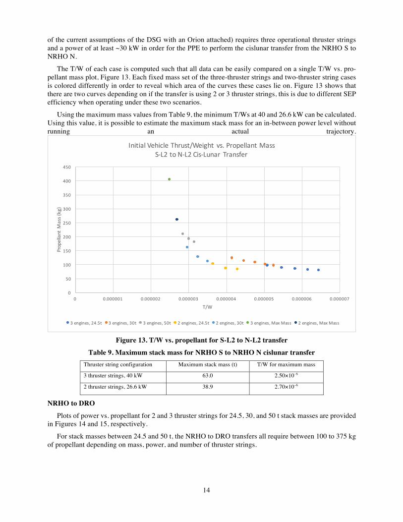
of the current assumptions of the DSG with an Orion attached) requires three operational thruster strings and a power of at least ~30 kW in order for the PPE to perform the cislunar transfer from the NRHO S to NRHO N.
The T/W of each case is computed such that all data can be easily compared on a single T/W vs. pro-pellant mass plot, Figure 13. Each fixed mass set of the three-thruster strings and two-thruster string cases is colored differently in order to reveal which area of the curves these cases lie on. Figure 13 shows that there are two curves depending on if the transfer is using 2 or 3 thruster strings, this is due to different SEP efficiency when operating under these two scenarios.
Using the maximum mass values from Table 9, the minimum T/Ws at 40 and 26.6 kW can be calculated. Using this value, it is possible to estimate the maximum stack mass for an in-between power level without running an actual trajectory.
Figure 13. T/W vs. propellant for S-L2 to N-L2 transfer
Table 9. Maximum stack mass for NRHO S to NRHO N cislunar transfer Thruster string configuration Maximum stack mass (t) T/W for maximum mass
3 thruster strings, 40 kW 63.0 2.50×10⁻⁶
2 thruster strings, 26.6 kW 38.9 2.70×10⁻⁶
NRHO to DRO
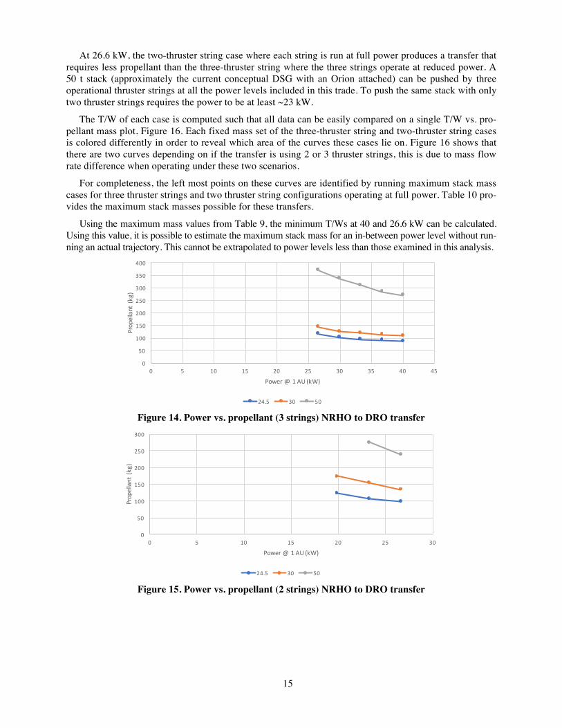
Plots of power vs. propellant for 2 and 3 thruster strings for 24.5, 30, and 50 t stack masses are provided in Figures 14 and 15, respectively.
For stack masses between 24.5 and 50 t, the NRHO to DRO transfers all require between 100 to 375 kg of propellant depending on mass, power, and number of thruster strings.
0
50
100
150
200
250
300
350
400
450
0 0.000001 0.000002 0.000003 0.000004 0.000005 0.000006 0.000007
PropellantM
ass(kg)
T/W
InitialVehicleThrust/Weight vs.PropellantMassS-L2toN-L2Cis-Lunar Transfer
3engines,24.5t 3engines,30t 3engines,50t 2engines,24.5t 2engines,30t 3engines,MaxMass 2engines,MaxMass
15
At 26.6 kW, the two-thruster string case where each string is run at full power produces a transfer that requires less propellant than the three-thruster string where the three strings operate at reduced power. A 50 t stack (approximately the current conceptual DSG with an Orion attached) can be pushed by three operational thruster strings at all the power levels included in this trade. To push the same stack with only two thruster strings requires the power to be at least ~23 kW.
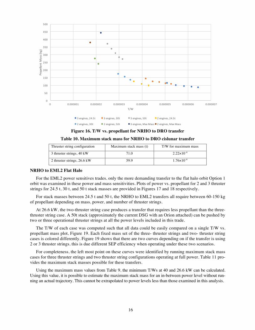
The T/W of each case is computed such that all data can be easily compared on a single T/W vs. pro-pellant mass plot, Figure 16. Each fixed mass set of the three-thruster string and two-thruster string cases is colored differently in order to reveal which area of the curves these cases lie on. Figure 16 shows that there are two curves depending on if the transfer is using 2 or 3 thruster strings, this is due to mass flow rate difference when operating under these two scenarios.
For completeness, the left most points on these curves are identified by running maximum stack mass cases for three thruster strings and two thruster string configurations operating at full power. Table 10 pro-vides the maximum stack masses possible for these transfers.
Using the maximum mass values from Table 9, the minimum T/Ws at 40 and 26.6 kW can be calculated. Using this value, it is possible to estimate the maximum stack mass for an in-between power level without run-ning an actual trajectory. This cannot be extrapolated to power levels less than those examined in this analysis.
Figure 14. Power vs. propellant (3 strings) NRHO to DRO transfer
Figure 15. Power vs. propellant (2 strings) NRHO to DRO transfer
0
50
100
150
200
250
300
350
400
0 5 10 15 20 25 30 35 40 45
Propellant(kg)
Power@1AU(kW)
Powervs.Propellant(3Engines)NRHOtoDROCis-Lunar Transfer
24.5 30 50
0
50
100
150
200
250
300
0 5 10 15 20 25 30
Propellant(kg)
Power@1AU(kW)
Powervs.Propellant(2Engines)NRHOtoDROCis-Lunar Transfer
24.5 30 50
16
Figure 16. T/W vs. propellant for NRHO to DRO transfer
Table 10. Maximum stack mass for NRHO to DRO cislunar transfer Thruster string configuration Maximum stack mass (t) T/W for maximum mass
3 thruster strings, 40 kW 71.0 2.22×10⁻⁶
2 thruster strings, 26.6 kW 59.9 1.76×10⁻⁶
NRHO to EML2 Flat Halo
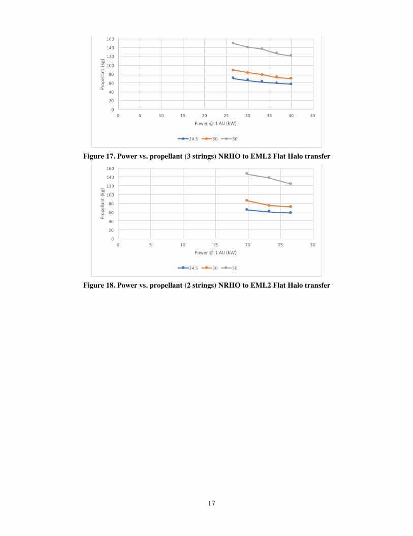
For the EML2 power sensitives trades, only the more demanding transfer to the flat halo orbit Option 1 orbit was examined in these power and mass sensitivities. Plots of power vs. propellant for 2 and 3 thruster strings for 24.5 t, 30 t, and 50 t stack masses are provided in Figures 17 and 18 respectively.
For stack masses between 24.5 t and 50 t, the NRHO to EML2 transfers all require between 60-150 kg of propellant depending on mass, power, and number of thruster strings.
At 26.6 kW, the two-thruster string case produces a transfer that requires less propellant than the three-thruster string case. A 50t stack (approximately the current DSG with an Orion attached) can be pushed by two or three operational thruster strings at all the power levels included in this trade.
The T/W of each case was computed such that all data could be easily compared on a single T/W vs. propellant mass plot, Figure 19. Each fixed mass set of the three- thruster strings and two- thruster string cases is colored differently. Figure 19 shows that there are two curves depending on if the transfer is using 2 or 3 thruster strings, this is due different SEP efficiency when operating under these two scenarios.
For completeness, the left most point on these curves were identified by running maximum stack mass cases for three thruster strings and two thruster string configurations operating at full power. Table 11 pro-vides the maximum stack masses possible for these transfers.
Using the maximum mass values from Table 9, the minimum T/Ws at 40 and 26.6 kW can be calculated. Using this value, it is possible to estimate the maximum stack mass for an in-between power level without run-ning an actual trajectory. This cannot be extrapolated to power levels less than those examined in this analysis.
0
50
100
150
200
250
300
350
400
450
500
0 0.000001 0.000002 0.000003 0.000004 0.000005 0.000006 0.000007
PropellantM
ass(kg)
T/W
InitialVehicleThrust/Weight vs.PropellantMassNRHOtoDROCis-Lunar Transfer
3engines,24.5t 3engines,30t 3engines,50t 2engines,24.5t
2engines,30t 2engines,50t 3engines,MaxMass 2engines,MaxMass
17
Figure 17. Power vs. propellant (3 strings) NRHO to EML2 Flat Halo transfer
Figure 18. Power vs. propellant (2 strings) NRHO to EML2 Flat Halo transfer
0
20
40
60
80
100
120
140
160
0 5 10 15 20 25 30 35 40 45
Propellant(kg)
Power@1AU(kW)
Powervs.Propellant(3Engines)S-L2toFlatEML2HaloCis-Lunar Transfer
24.5 30 50
0
20
40
60
80
100
120
140
160
0 5 10 15 20 25 30
Propellant(kg)
Power@1AU(kW)
Powervs.Propellant(2Engines)S-L2toFlatEML2HaloCis-Lunar Transfer
24.5 30 50

18
Figure 19. T/W vs. propellant for NRHO to EML2 Flat Halo transfer
Table 11. Maximum stack mass for NRHO to EML2 Flat Halo cislunar transfer Thruster string configuration Maximum stack mass (t) T/W for maximum mass
3 thruster strings, 40 kW 121 1.31x10⁻⁶
2 thruster strings, 26.6 kW 90.8 1.37x10⁻⁶
COMPARISON OF SEP VS. CHEMICAL PROPULSION FOR CISLUNAR TRANSFERS
In order to compare the performance of the SEP system for cislunar transfers, a similar set of transfers are run using performance parameters of a representative chemical propulsion system. Assuming impulsive burns, and an Isp of 300 s, this section gathers together example cases of performing the same cislunar orbit transfers as previously shown using the SEP system. For each of these impulsive trajectories, the trip times are comparable to those of the SEP low thrust trajectories. This is because the cislunar orbit transfers depend more on the locations of the Earth and the Moon than the magnitude of the thrust.
Transfers to the NRHO and from the NRHO to other cislunar orbits are modeled for the 40 kW SEP system, in which all 3 active thrusters are used at full power and compared to similar transfers using an impulsive chemical propulsion system. The results of these analyses are captured in Table 12. The trip times for the low thrust vs. impulsive cislunar orbit transfer between the NRHO S and the NRHO N and the NRHO to the DRO are comparable. The transfer from NRHO to the flat EML2 Option 1 is not completed for a representative chemical system. A series of transfers for the Option 2 perpendicular EML2 are per-formed, and these show the same trend as the other two cislunar transfers.
0
50
100
150
200
250
300
350
400
0 0.000001 0.000002 0.000003 0.000004 0.000005 0.000006 0.000007
PropellantM
ass(kg)
T/W
InitialVehicleThrust/Weight vs.PropellantMassNRHOtoEML2Cis-Lunar Transfer
3engines,24.5t 3engines,30t 3engines,50t 2engines,24.5t
2engines,30t 2engines,50t 3engines,MaxMass 2engines,MaxMass
19
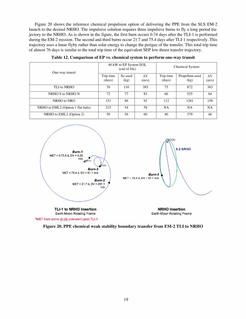
Figure 20 shows the reference chemical propulsion option of delivering the PPE from the SLS EM-2 launch to the desired NRHO. The impulsive solution requires three impulsive burns to fly a long period tra-jectory to the NRHO. As is shown in the figure, the first burn occurs 0.74 days after the TLI-1 is performed during the EM-2 mission. The second and third burns occur 21.7 and 75.4 days after TLI-1 respectively. This trajectory uses a lunar flyby rather than solar energy to change the perigee of the transfer. This total trip time of almost 76 days is similar to the total trip time of the equivalent SEP low thrust transfer trajectory.
Table 12. Comparison of EP vs. chemical system to perform one-way transit
One-way transit
40 kW to EP System EOL (end of life) Chemical System
Trip time (days)
Xe used (kg)
DV (m/s)
Trip time (days)
Propellant used (kg)
DV (m/s)
TLI to NRHO 76 110 385 75 872 363
NRHO S to NRHO N 72 77 83 66 525 64
NRHO to DRO 151 86 92 112 1281 158
NRHO to EML2 (Option 1 flat halo) 215 54 58 NA NA NA
NRHO to EML2 (Option 2) 50 56 60 40 379 46
Figure 20. PPE chemical weak stability boundary transfer from EM-2 TLI to NRHO
20
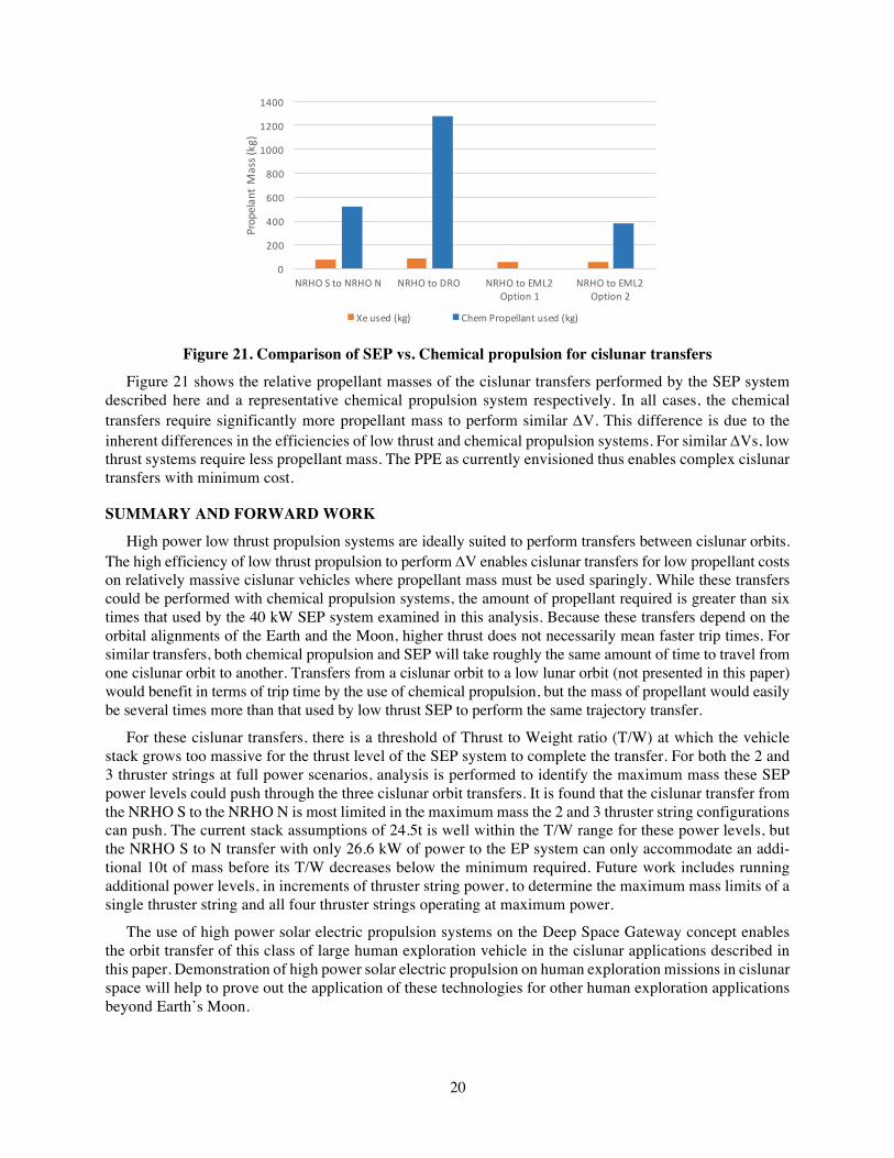
Figure 21. Comparison of SEP vs. Chemical propulsion for cislunar transfers
Figure 21 shows the relative propellant masses of the cislunar transfers performed by the SEP system described here and a representative chemical propulsion system respectively. In all cases, the chemical transfers require significantly more propellant mass to perform similar DV. This difference is due to the inherent differences in the efficiencies of low thrust and chemical propulsion systems. For similar DVs, low thrust systems require less propellant mass. The PPE as currently envisioned thus enables complex cislunar transfers with minimum cost.
SUMMARY AND FORWARD WORK
High power low thrust propulsion systems are ideally suited to perform transfers between cislunar orbits. The high efficiency of low thrust propulsion to perform DV enables cislunar transfers for low propellant costs on relatively massive cislunar vehicles where propellant mass must be used sparingly. While these transfers could be performed with chemical propulsion systems, the amount of propellant required is greater than six times that used by the 40 kW SEP system examined in this analysis. Because these transfers depend on the orbital alignments of the Earth and the Moon, higher thrust does not necessarily mean faster trip times. For similar transfers, both chemical propulsion and SEP will take roughly the same amount of time to travel from one cislunar orbit to another. Transfers from a cislunar orbit to a low lunar orbit (not presented in this paper) would benefit in terms of trip time by the use of chemical propulsion, but the mass of propellant would easily be several times more than that used by low thrust SEP to perform the same trajectory transfer.
For these cislunar transfers, there is a threshold of Thrust to Weight ratio (T/W) at which the vehicle stack grows too massive for the thrust level of the SEP system to complete the transfer. For both the 2 and 3 thruster strings at full power scenarios, analysis is performed to identify the maximum mass these SEP power levels could push through the three cislunar orbit transfers. It is found that the cislunar transfer from the NRHO S to the NRHO N is most limited in the maximum mass the 2 and 3 thruster string configurations can push. The current stack assumptions of 24.5t is well within the T/W range for these power levels, but the NRHO S to N transfer with only 26.6 kW of power to the EP system can only accommodate an addi-tional 10t of mass before its T/W decreases below the minimum required. Future work includes running additional power levels, in increments of thruster string power, to determine the maximum mass limits of a single thruster string and all four thruster strings operating at maximum power.
The use of high power solar electric propulsion systems on the Deep Space Gateway concept enables the orbit transfer of this class of large human exploration vehicle in the cislunar applications described in this paper. Demonstration of high power solar electric propulsion on human exploration missions in cislunar space will help to prove out the application of these technologies for other human exploration applications beyond Earth’s Moon.
0
200
400
600
800
1000
1200
1400
NRHOStoNRHON NRHOtoDRO NRHOtoEML2Option1
NRHOtoEML2Option2
PropelantMass(kg)
Cislunar Transits- PropellantComparisons
Xeused(kg) ChemPropellantused(kg)
21
1 R. Whitley and R. Martinez, “Options for Staging Orbits in Cis-Lunar Space,” Oct. 21, 2015. IEEE Aerospace Conference; 5-12 Mar. 2016; Big Sky, MT, JSC-CN-35647. 2 J. Williams, D.E. Lee, Ryan J. Whitley, Kevin A. Bokelmann, Briane C. Davis, and Christopher F. Berry. “Targeting Cislunar Near Rectilinear Halo Orbits for Human Space Exploration,” AAS/AIAA Space Flight Mechanics Meeting; 27th; 5-9 Feb. 2017; San Antonio, TX; United States, AAS 17-267. 3 Hambleton, K. “Deep Space Gateway to Open Opportunities for Distant Destinations.” NASA. NASA, 28 Mar. 2017. Web. 25 May 2017. https://www.nasa.gov/feature/deep-space-gateway-to-open-opportunities-for-distant-destinations 4 J.R. Brophy, D. Landau, T. McElrath, G. Lantoine, T. Lam, M. McGuire, L. Burke, M. Martini, J. Dankanich,, “Synergies of Robotic Asteroid Redirection Technologies and Human Space Exploration,” 5th International Astronautical Congress, Toronto, Canada. IAC-14.A5.3-B3.6.7, x26388 5 N. Strange, D. Landau, T. McElrath, G. Lantoine, T. Lam, M. McGuire, L. Burke, M. Martini, and J. Dankanich, “Overview of Mission Design for NASA Asteroid Redirect Robotic Mission Concept,” IEPC-2013-321. International Electric Propulsion Con-ference (IEPC2013); 33rd; 6-10 Oct. 2013; Washington, D. C. 6 D. Herman, L. Friedman, N.J. Strange, D. Landau, T. Jones, R. Schweickart, C. Lewicki, M. Elvis, and D. Manzella, “The Ion Propulsion System for the Asteroid Redirect Robotic Mission,” Propulsion and Energy Forum, 52nd AIAA/SAE/ASEE Joint Pro-pulsion Conference, July 25-27, 2016, Salt Lake City, UT, AIAA-2016-4824. 7 C. Ocampo and J. Senent, “The Design and Development of COPERNICUS: A Comprehensive Trajectory Design and Optimi-zation System,” Paper IAC-06-C1.4.04, Oct. 2006 8 J. Williams, “Copernicus Trajectory Design and Optimization System,” NASA. NASA, 3 Nov. 2016. Web. 11 Jan. 2017. https://www.nasa.gov/centers/johnson/copernicus/index.html 9 K. Howell and J. Breakwell, “Almost Rectilinear Halo Orbits,” 20thAerospaceSciencesMeeting,1982. 10 J. Williams, D.E. Lee, R.L. Whitley, K.A. Bokelmann, D.C. Davis, and C.F. Berry, “Targeting Cislunar Near Rectilinear Halo Orbits for Human Space Exploration,” 27th AAS/AIAA Space Flight Mechanics Meeting, Feb. 2017. 11 D.C. Davis, S.A. Bhatt, K.C. Howell, J. Jang, R.L. Whitley, F.D. Clark, D. Guzzetti, E.M. Zimovan, and G.H. Barton, “Orbit Maintenance and Navigation of Human Spacecraft in Cislunar Near Rectilinear Halo Orbits,” AAS/AIAA Spaceflight Mechanics Meeting, San Antonio, Texas, February 2017. 12 J. Brophy, L. Friedman, and F. Culick, “Asteroid Retrieval Feasibility,” DOI: 10.1109/AERO.2012.6187031, IEEE Aerospace Conf., March 2012.
REFERENCES