Embed Size (px)
Citation preview

AAllpphhaa 550000ii SSeerriieess
II nn dd uu ss tt rr ii aa ll RR aa dd ii oo RR ee mm oo tt ee CC oo nn tt rr oo ll SS yy ss tt ee mm
OOppeerraattiioonn && PPaarrttss MMaannuuaall
Williams USA, LLC
38113 Plymouth Rd., Livonia, Michigan 48150
Phone: 1-734-416-5520, Fax: 1-734-416-1907
Web site: www.williamsyrless.com
E-mail: [email protected]

1
IIMMPPOORRTTAANNTT NNOOTTEESS!!
1. Startup Procedure _ You must make sure that the red EMS button located on the top
right-hand side of the transmitter is elevated prior to turning “on” the power (battery) switch, by
twisting it 1/4 turn clockwise, it will pop up. Then turn “on” the power (battery) switch
located on the top left-hand side of the transmitter. The Status LED at the center of the power
switch will display a green light for up to 2 seconds when the power switch is turned “on”.
Note A: Whenever the EMS button is depressed you must reenact the Startup Procedure,
that is, elevate the EMS button then turn the power (battery) switch “Off” then
back “On”.
Note B: Depressing (holding down) any buttons during the “Startup Procedure” will
disable the transmitter.
2. Receiver Main Relay will remain closed until the Stop command is received. The factory
default setting for the “JP2” Jumper is open; that is, the Main Relay will remain closed until the
Stop command has been received. Replacing the “JP2” Jumper (shorted) will cause the Main Relay
to time open 5 minutes after the last command was received. Note that depressing any transmitter
button (except select) will close the Main Relay and instituted the appropriate command. If your
crane or hoist is equipped with a VFD drive shorting the “JP2” can cause an unacceptable delay, in
this situation we suggest you leave the JP2 jumper off (open), then the Main relay will remain
closed until the Stop command is received, see Section 7.3 for details.
3. Caution! Improper Storage of your Spare Transmitter is a Safety Hazard! _ During
the initial installation of your remote control system the spare (second) transmitter should
be tested to confirm that it is functioning properly and then the batteries must be removed
and the transmitter stored in a secured place. Failure to follow this safety procedure
can result in the inadvertent operation of your crane or hoist by unauthorized
personnel resulting in serious injury or death!

2
TTAABBLLEE OOFF CCOONNTTEENNTTSS
Page
1. SAFETY INSTRUCTION ............................................................................................. 3
2. PUSHBUTTON CONFIGURATION
2.1 Alpha 504i ................................................................................................... 4
Alpha 508i ................................................................................................... 4
Alpha 512i ............................................................................................... 6
3. TRANSMITTER OUTLINE
3.1 Alpha 504i/508i/512i ........................................................................................ 7
3.2 Spare Parts ........................................................................................................ 8
4. RECEIVER OUTLINE
4.1 Alpha 504i External/Internal Assembly................................................................. 9-10
4.2 Alpha 508i External/Internal Assembly................................................................ 11-12
4.3 Alpha 512i External/Internal Assembly.................................................................. 13-14
5. OUTPUT CONTACT DIAGRAMS
5.1 Alpha 504i …............................................................................................. 15
5.2 Alpha 508i ................................................................................................. 15-16
5.3 Alpha 512i ................................................................................................. 17-20
6. TRANSMITTER SETTING
6.1 How to Set ID Codes ............................................................................................. 21
6.2 Transmitter RF Channel Setting ............................................................................. 21
7. RECEIVER SETTING
7.1 How to Set Receiver ID Codes .............................................................................. 22
7.2 Receiver RF Channel Setting .............................................................................. 22
7.3 Receiver Function Setting .............................................................................. 23-26
7.4 Frequency (RF) Channels Table .............................................................................. 27
8. TRANSMITTER OPERATION & STATUS LIGHT
8.1 Transmitter Operating Steps .............................................................................. 28-29
8.2 SMI, SSI, MSS/FSI Features ............................................................................. 29-30
8.3 Transmitter Status light .............................................................................. 31-32
9. RECEIVER INSTALLATION
9.1 Preparation for Installation ................................................................................... 32
9.2 Step-By-Step Installation ....................................................................................... 32-33
9.3 System Testing ....................................................................................................... 34
9.4 Receiver System Status LED Display..................................................................... 34
10. TROUBLE SHOOTING................................................................................................. 35
11. SYSTEM SPECIFICATION ........................................................................................ 36
12. PARTS LIST ................................................................................................................. 37-38

3
1. SSAAFFEETTYY IINNSSTTRRUUCCTTIIOONN
The Alpha 500i series are relatively simple to use, however, it is very important to observe the proper
safety procedures before, during, and after operation. When used properly, the Alpha 500i series will
enhance safety, productivity and efficiency in the workplace.
The following procedures should be strictly followed:
1. Do not change the IDs on transmitter encoder and receiver decoder boards at will.
2. Be sure to replace the batteries with the same brand and specification at the same time. Do not
replace only one battery in the battery compartment otherwise there will have the condition of limited
transmitter operating time, battery leakage and overheating when charging.
3. Check the transmitter casing and pushbuttons daily. Should any damage that could inhibit the
proper operation of the transmitter be found the unit should be immediately removed from service.
4. Check the transmitter voltage whenever it is operated.
5. The red emergency stop button (EMS) should be checked at the beginning of each shift to ensure it is
in proper working order and the “Stop” command is being received by the receiver.
6. In the event of an emergency press down the EMS button will immediately deactivates the receiver
MAIN relay and the transmitter power. Then turned the power “off ” from the main power source to
the crane or equipment.
7. Do not use the same RF channel and ID code as any other system in use at the same facility or within
300-meter distance.
8. Ensure the waist belt is worn at all time during operation to avoid accidental damage to the
transmitter.
9. Rotate the power switch to OFF position when the transmitter is not operated temporarily or the
operation is finished.
10. Any repair or adjustment should be proceeding by repair technician for radio remote controls.
11. The operator should not change any electrical parts at will.
12. This device complies with Part 15 of the FCC Rules and with Industry Canada license-exempt RSS
standard(s). Operation is subject to the following two conditions: (1) This device may not cause
harmful interference, and (2) This device must accept any interference received, including
interference that may cause undesired operation.
13. Le présent appareil est conforme aux CNR d'Industrie Canada applicables aux appareils radio
exempts de licence. L'exploitation est autorisée aux deux conditions suivantes : (1) l'appareil ne doit
pas produire de brouillage, et (2) l'utilisateur de l'appareil doit accepter tout brouillage
radioélectrique subi, même si le brouillage est susceptible d'en compromettre le fonctionnement.
Note: Changes or modifications not expressively approved by the party responsible for
compliance could void the user's authority to operate the equipment. The term "IC:" before
the radio certification number only signifies that Industry Canada Specifications were met.

- 4 -
STOPPOWER
FOM TECH
S/ N:
FREQ:
MOD:
VOLT:
CH.
I D:
W
ME
W2
WS
Q SQ
AC AC
EW2
M
ED
2D
U2
U
U2
D2E
D
U
POWER
5A
5A
5ALV
E/W
MAIN
U/D
5A
Anti-vibration springmust be grounded
4
5
6
7
9
8
2
3
1
10
11
Below are some of many types of pushbutton configurations that are also available,
please contact your dealer for more details.
Interlocked (Can also be set to non-interlocked via an external programmer unit)
2. PPUUSSHHBBUUTTTTOONN CCOONNFFIIGGUURRAATTIIOONN
2.1 Alpha 504i Subgroup
1. Alpha 504A -- (4) single speed pushbuttons
2. Alpha 504B -- (4) double speed pushbuttons
Front View Back View
1) Receiver enclosure 5) System frequency 9) Supplied voltage
2) Wiring diagram 6) System serial number 10) Anti-vibration spring
3) Receiver LED displays* 7) System ID code 11) Grounding (GND)
4) Type model 8) System RF channel

- 5 -
STOPPOWER
FOM TECH
STOPPOWER
FOM TECH
STOPPOWER
FOM TECH
STOPPOWER
FOM TECH
STOPPOWER
FOM TECH
STOPPOWER
FOM TECH
2.2 Alpha 508i Subgroup
1. Alpha 507A -- (7) single speed pushbuttons
2. Alpha 507B -- (6) double speed pushbuttons + (1) single speed pushbuttons
3. Alpha 507AT -- (6) single speed pushbuttons + (1) SELECT I/II pushbutton
4. Alpha 507BT -- (6) double speed pushbuttons + (1) SELECT I/II pushbutton
5. Alpha 508A -- (8) single speed pushbuttons
6. Alpha 508B -- (6) double speed pushbuttons + (2) single speed pushbuttons
(Alpha 507A) (Alpha 507B) (Alpha 507AT) (Alpha 507BT) (Alpha 508A) (Alpha 508B)
AC
SQ
MA
W
SN
E
UD
AC
SQ
MA
S/ N:
FREQ:
MOD:
VOLT:
CH.
I D:
FILT
ER
Anti-vibration springmust be grounded
POWER
MAIN F65A
F1
F5 5A
LV/AUX1
COM417
L2(X2)
L1(X1)
GRN/YEL
COM5
MAIN
22
FF1
21
20
18
19
AUX1
AUX2
NC
COM3
NC
COM2
15
16
14 LV
N1
S1
COM1
D1
W1
E1
NC
NC
U1
F4 5A
F3 5A
13
10
11
12
9
8
3
5
6
7
4F2 5A
2
1
BRIDGE
TROLLEY
HOIST
/AUX2
4
5
6
7
9
8
2
3
1
10
11
Front View Back View
1) Receiver enclosure 5) System frequency 9) Supplied voltage
2) Wiring diagram 6) System serial number 10) Anti-vibration spring
3) Receiver LED displays* 7) System ID code 11) Grounding (GND)
4) Type model 8) System RF channel

- 6 -
STOPPOWER
FOM TECH
STOPPOWER
FOM TECH
STOPPOWER
FOM TECH
STOPPOWER
FOM TECH
1
2
3
4
2.3 Alpha 512i Subgroup 1. Alpha 512A -- (12) one-speed pushbuttons
2. Alpha 512B -- (11) one-speed pushbuttons + I/II select pushbutton*
3. Alpha 512C-1 -- (6) two- speed + (6) one-speed pushbuttons
4. Alpha 512C-2 -- (8) two-speed + (4) one-speed pushbuttons
5. Alpha 512D -- (10) two-speed + (2) one-speed pushbuttons
6. Alpha 512E-1 -- (6) two-speed + (5) one-speed pushbuttons + I/II select pushbutton*
7. Alpha 512E-2 -- (8) two-speed + (3) one-speed pushbuttons + I/II select pushbutton*
* For cranes with auxiliary hoist and trolley (changeover function).
1) Transparent top cover 3) Mounting bracket with shock absorbers
2) Light-gray colored base 4) Cable gland / Cord grip
α512C-1/C-2/D
α512E-1/E-2 α512A α512B

- 7 -
33.. TTRRAANNSSMMIITTTTEERR OOUUTTLLIINNEE
(Alpha 504i) (Alpha 508i) (Alpha 512i)
Transmitter encoder board and induction charging board:
Transmitter Internal Assembly:
(1) Internal antenna
(2) Status LED display
(3) Battery contact
(4) Programming port
(5) Function setting
Dip-switch
(6) JP2 setting pin
(7) JP1 setting pin
Alpha 504i transmitter size : 140mm x 68mm x 30mm
Alpha 508i transmitter size : 189mm x 68mm x 30mm
Alpha 512i transmitter size : 235mm x 68mm x 30mm

- 8 -
3.2 Spare Parts
(1) Transmitter shock-absorbing rubber
(2) Shoulder strap
(3) AA alkaline batteries

- 9 -
S/ N:
FREQ:
MOD:
VOLT:
CH.
I D:
W
ME
W2
WS
Q SQ
AC AC
EW2
M
ED
2D
U2
U
U2
D2E
D
U
POWER
5A
5A
5ALV
E/W
MAIN
U/D
5A
Anti-vibration springmust be grounded
4
5
6
7
9
8
2
3
1
10
11
44.. RREECCEEIIVVEERR OOUUTTLLIINNEE
44..11 AAllpphhaa 550044ii
44..11..11 EExxtteerrnnaall AAsssseemmbbllyy
SIZE:310mm X 134mm X 72mm
Front View Back View
1) Receiver enclosure 5) System frequency 9) Supplied voltage
2) Wiring diagram 6) System serial number 10) Anti-vibration spring
3) Receiver LED displays* 7) System ID code 11) Grounding (GND)
4) Type model 8) System RF channel
* A ~ AUX Relay Contact Indicator (for Alpha 540A/560A models only).
* M ~ MAIN and 2nd Speed Relay Contact Indicator.
Green "on" → MAIN activated (All models).
Red "on" → 2nd speed activated (for Alpha 560S/A models only).
* SQ ~ RF Signal Indicator (Red).
"on" → RF signal detected and received.
"off" → No RF signal detected or received.
Blinking at transmitter power "off" → Other radio interference.
* AC ~ Power Source Indicator (red) "on" → AC input power supplied.
"off" → No AC input power.

- 10 -
1 8
7
9
10
14
15
6
12
19
FUSE
4
5
FUSE
FUSE
FUSE
11
FUSE
13
16
3
2
17
18
1
2
3
4
44..11..22 AAllpphhaa 550044ii IInntteerrnnaall AAsssseemmbbllyy
(Fig. 15) Internal Parts Assembly
1) Receiving RF module
2) External programming port
3) Power module *
4) Secondary power AC fuse (F1)
5) Primary power AC fuse (FF1)
6) Internal Antenna
7) System status LED display*
8) External antenna port
9) ID code dip-switch
10) RF channel dip-switch
11) Contact relay LED display
12) Pushbutton #1 and #2 fuse (5.0A)
13) MAIN fuse (5.0A)
14) Contact output seat (CN3)
15) Low-voltage (LV) fuse (5.0A)
16) Contact output seat (CN4)
17) Pushbutton #3 and #4 fuse (5.0A)
18) AC power input seat (CN2)
19) Cable gland & output cable
* Power module: Including transformer or full-voltage
module.
* Please refer to the following table for Alpha
504/507/508/512 receiver power fuse list.
** Please refer to page 34 for system status
LED display information.
1) Spare fuse & jumper compartment
2) Spare Jumper slots
3) Spare fuse slots
4) Receiver top casing

- 11 -
44..22 AAllpphhaa 550088ii
44..22..11 EExxtteerrnnaall AAsssseemmbbllyy
SIZE:310mm X 134mm X 72mm
AC
SQ
MA
W
SN
E
UD
AC
SQ
MA
S/ N:
FREQ:
MOD:
VOLT:
CH.
I D:
FILT
ER
Anti-vibration springmust be grounded
POWER
MAIN F65A
F1
F5 5A
LV/AUX1
COM417
L2(X2)
L1(X1)
GRN/YEL
COM5
MAIN
22
FF1
21
20
18
19
AUX1
AUX2
NC
COM3
NC
COM2
15
16
14 LV
N1
S1
COM1
D1
W1
E1
NC
NC
U1
F4 5A
F3 5A
13
10
11
12
9
8
3
5
6
7
4F2 5A
2
1
BRIDGE
TROLLEY
HOIST
/AUX2
4
5
6
7
9
8
2
3
1
10
11
Front View Back View
1) Receiver enclosure 5) System frequency 9) Supplied voltage
2) Wiring diagram 6) System serial number 10) Anti-vibration spring
3) Receiver LED displays* 7) System ID code 11) Grounding (GND)
4) Type model 8) System RF channel

- 12 -
FUSE
FUSE
FUSE
1
2
9
5
12
11
13
14
15
16
18
19
10
17
21
FUSE
FUSE
FUSE
4
6
7
8
20
3
44..22..22 AAllpphhaa 550088ii IInntteerrnnaall AAsssseemmbbllyy
(Fig. 16) Internal Parts Assembly
1) Receiving RF module
2) External programming port
3) Power module
4) Secondary power AC fuse (F1)
5) Contact output seat (CN8)
6) Primary power AC fuse (FF1)
7) AC power input seat (CN2)
8) Internal Antenna
9) System Status LED display**
10 )External antenna port
11) ID code dip-switch
12) RF channel dip-switch
13) Contact relay LED display
14) Pushbutton #1and #2 fuse (5.0A)
15) Contact output seat (CN3)
16) MAIN contact fuse (5.0A)
17) Pushbutton #3 and #4 fuse (5.0A)
18) Pushbutton #5 and #6 fuse (5.0A)
19) Contact output seat (CN4)
20) LV & AUX fuse (5.0A)
21) Cable gland & output cable
* Power module: Including transformer or
full-voltage module.
* Please refer to the following table for Alpha
504/507/508/512 receiver power fuse list.
** Please refer to page 34 for system status
LED display information.
Alpha 504/507/508/512 Receiver Power Fuse List
Type Parts No. Voltage
DC12V~24V AC24 AC36~48V AC100~120
V AC220~240
V AC380~440
V AC100~240V Full-Voltage
α504
α508
FF1 3A 1A 2A
F1 3A 2A 0.5A 1A
Α512 FF1 3A 1A
F1 3A 2A 0.8A

- 13 -
1
2
3
4
44..33 AAllpphhaa 551122ii
44..33..11 EExxtteerrnnaall AAsssseemmbbllyy
SIZE:300mm X 230mm X 86mm
External Parts Assembly
3) Transparent top cover 3) Mounting bracket with shock absorbers
4) Light-gray colored base 4) Cable gland / Cord grip

- 14 -
17
20
19
18
16
14
5
10
11
9
7
8
6
1
3
4
2 15
12
13
44..33..22 AAllpphhaa 551122ii IInntteerrnnaall AAsssseemmbbllyy
Internal Parts Assembly
1) Power LED display* 13) Internal Antenna
2) SQ LED display** 14) Receiving RF module
3) Status LED display**** 15) External antenna port
4) DC power relay LED display*** 16) RF channel dip-switch
5) Programming port 17) ID code dip-switch
6) Jumper settings 18) Secondary power fuse F1*(Please refer to table 4.3)
7) Function dip-switch 19) Voltage selector seat
8) Pushbutton #3 and #4 relay fuse (5.0A) 20) MAIN relay fuse (5.0A)
9) Pushbutton #5 and #6 relay fuse (5.0A) 21) Pushbutton A4 relay fuse (5.0A)
10) Pushbutton A1and A2 relay fuse (5.0A) 22) Primary power fuse FF1*(參考下列對照表 4.3)
11) Pushbutton A3 relay fuse (5.0A) 23) Low-voltage (LV) relay fuse (5.0A)
12) Pushbutton #1 and #2 relay fuse (5.0A) 24) Power port CN2
* POWER ~ AC Power Source Indicator "on" → AC input power supplied.
"off" → No AC input power.
** SQ ~ RF Signal Indicator "on" → RF signal detected and received.
"off" → No RF signal detected or received.
Blinking at transmitter power “off” → Other radio interference.
*** RELAY_COM ~ DC Power Source to Relays "on" → DC power to relays.
"off" → No DC power to relays.
**** STATUS ~ Receiver System Status LED Display → Please refer to page 34.

- 15 -
POWER
5A
5A
5ALV
E/W
MAIN
U/D
5A
POWER
5A
5A
5ALV
E/W
MAIN
U/D
5A
FILTER
Anti-vibration springmust be grounded
POWER
MAIN F65A
F1
F5 5A
LV/AUX1
COM417
L2(X2)
L1(X1)
GRN/YEL
COM5
MAIN
22
FF1
21
20
18
19
AUX1
NC
NC
COM3
NC
COM2
15
16
14 LV
N1
S1
COM1
D1
W1
E1
NC
NC
U1
F4 5A
F3 5A
13
10
11
12
9
8
3
5
6
7
4F2 5A
2
1
BRIDGE
TROLLEY
HOIST
FILTER
Anti-vibration springmust be grounded
POWER
MAIN F65A
F1
F5 5A
LV/AUX1
BRIDGEF4 5A
TROLLEYF3 5A
COM417
L2(X2)
L1(X1)
GRN/YEL
COM5
MAIN
22
FF1
21
20
18
19
AUX1
NC
N/S2
COM3
E/W2
COM2
15
16
14
13
LV
N110
11
12
S1
9
8
COM1
D13
5
6
7 W1
E1
4 D2
HOISTF2 5A
2
1
U2
U1
FOM TECH
PB1PB2
PB4 PB3
FOM TECH
PB1PB2
PB4 PB3
PB5PB6
PB8 PB7
55.. OOUUTTPPUUTT CCOONNTTAACCTT DDIIAAGGRRAAMMSS
55..11 AAllpphhaa 550044ii MMooddeellss
(Alpha 504A) (Alpha 504B)
55..22 AAllpphhaa 550088ii MMooddeellss
((Alpha 507A) (Alpha 507B)

- 16 -
FILTER
Anti-vibration springmust be grounded
POWER
MAIN F65A
F1
F5 5A
LV/SEL-I
COM417
L2(X2)
L1(X1)
GRN/YEL
COM5
MAIN
22
FF1
21
20
18
19
SEL-I
SEL-II
NC
COM3
NC
COM2
15
16
14 LV
N1
S1
COM1
D1
W1
E1
NC
NC
U1
F4 5A
F3 5A
13
10
11
12
9
8
3
5
6
7
4F2 5A
2
1
BRIDGE
TROLLEY
HOIST
/SEL-II
FILTER
Anti-vibration springmust be grounded
POWER
MAIN F65A
F1
F5 5A
LV/SEL-I
BRIDGEF4 5A
TROLLEYF3 5A
COM417
L2(X2)
L1(X1)
GRN/YEL
COM5
MAIN
22
FF1
21
20
18
19
SEL-I
SEL-II
N/S2
COM3
E/W2
COM2
15
16
14
13
LV
N110
11
12
S1
9
8
COM1
D13
5
6
7 W1
E1
4 D2
HOISTF2 5A
2
1
U2
U1
/SEL-II
FILTER
Anti-vibration springmust be grounded
POWER
MAIN F65A
F1
F5 5A
LV/AUX1
COM417
L2(X2)
L1(X1)
GRN/YEL
COM5
MAIN
22
FF1
21
20
18
19
AUX1
AUX2
NC
COM3
NC
COM2
15
16
14 LV
N1
S1
COM1
D1
W1
E1
NC
NC
U1
F4 5A
F3 5A
13
10
11
12
9
8
3
5
6
7
4F2 5A
2
1
BRIDGE
TROLLEY
HOIST
/AUX2
FOM TECH
PB1PB2
PB4 PB3
PB5PB6
PB8 PB7
FILTER
Anti-vibration springmust be grounded
POWER
MAIN F65A
F1
F5 5A
LV/AUX1
BRIDGEF4 5A
TROLLEYF3 5A
COM417
L2(X2)
L1(X1)
GRN/YEL
COM5
MAIN
22
FF1
21
20
18
19
AUX1
AUX2
N/S2
COM3
E/W2
COM2
15
16
14
13
LV
N110
11
12
S1
9
8
COM1
D13
5
6
7 W1
E1
4 D2
HOISTF2 5A
2
1
U2
U1
/AUX2
((Alpha 507AT) (Alpha 507BT)
((Alpha 508A) (Alpha 508B)

- 17 -
FOM TECH
PB1PB2
PB4 PB3
PB5PB6
PB8 PB7
PB9
FOM TECH
PB1PB2
PB4 PB3
PB5PB6
PB8 PB7
PB9
I\II
55..33 AAllpphhaa 551122ii MMooddeellss
(Alpha 512A)
(Alpha 512B)

- 18 -
FOM TECH
PB1PB2
PB4 PB3
PB5PB6
PB8 PB7
PB9
FOM TECH
PB1PB2
PB4 PB3
PB5PB6
PB8 PB7
PB9
(Alpha 512C-1)
(Alpha 512C-2)

- 19 -
FOM TECH
PB1PB2
PB4 PB3
PB5PB6
PB8 PB7
PB9
FOM TECH
PB1PB2
PB4 PB3
PB5PB6
PB8 PB7
PB9
I\II
(Alpha 512D)
(Alpha 512E-1)

- 20 -
FOM TECH
PB1PB2
PB4 PB3
PB5PB6
PB8 PB7
PB9
I\II
(Alpha 512E-2)

- 21 -
66.. TTRRAANNSSMMIITTTTEERR SSEETTTTIINNGGSS
66..11 HHooww ttoo SSeett IIDD CCooddeess
Set by programming tool or adjust encoder board JP1, 1st / 2nd pin and dip-switch.
For the location of the jumper of Alpha 504/507/508 models, please refer to page 10.
(1) Rotate the transmitter power to OFF position
(2) Disassemble shock-absorbing rubber
(3) Put the transmitter pushbutton downward and disassemble transmitter bottom casing.
(4) Set the transmitter ID code with the dip-switch on the encoder board and put jumper on the 1st and
2nd pin of JP1.
(5) Make sure the batteries are installed properly.
(6) Rotate the transmitter power switch to ON position.
(7) Green status LED ON for 0.1 sec, OFF for 0.1 sec, flash for 1 sec. (5 times)
(8) Green status LED steady ON indicates the setting is completed. If the LED status light is changed to red,
the setting is failed. Please repeat the above setting steps until the setting is successful.
(9) After setting is completed and successful, remove jumper on 1, 2 pin of JP1.
(10) Rotate transmitter power switch to OFF position.
編碼板
Back view Position of dip-switch & jumpers
Top slot ON “1”; bottom slot “0”. The setting above is 00000011.
66..22 TTrraannssmmiitttteerr CChhaannnneell SSeettttiinnggss
Set by programming tool or adjust encoder board 2nd & 3rd pin of JP1 and dip-switch.
Available channels form 01 ~ 68.
When setting frequency on TX board JP1, put jumper on 2nd & 3rd pin of JP1.
Change the frequency needed by changing the dip-switch setting. Repeat the previous steps to set frequency.
Example:Set channel as 03→(00000011) → Correct setting

- 22 -
77.. RREECCEEIIVVEERR SSEETTTTIINNGGSS
77..11..11 HHooww ttoo SSeett AAllpphhaa 550044ii aanndd 550088ii RReecceeiivveerr IIDD CCooddee
ID DIP-SW
Top slot “1” Bottom slot “0”
Set the ID codes needed on the decoder board dip-switch.
For example: the ID codes set above 10000111.
77..11..22 HHooww ttoo SSeett AAllpphhaa 551122ii RReecceeiivveerr IIDD CCooddee
Please refer receiver internal parts assembly for ID code 8-position dip-switch to set receiver ID code.
Top slot “1”; bottom slot “0”
Set the ID codes needed on the decoder board dip-switch.
For example: the ID codes → 10010110
(“1”value adds up must to be “4”)
7.2 Receiver RF Channel Setting
There are 68 sets of user-adjustable receiving RF channels that can be set manually via a 8-position dip-switch
located to the right of the receiving RF module. Change the receiving RF channel simply by resetting these
8-position dip-switch. For the location of the receiving RF module, please refer to fig. 15, 16, and 18 on page 12,
13, and 14.
Top slot “1”; bottom slot “0”
For example:the channel dip-switch set above 00000101, channel 05.
1 2 3 4 5 6 7 8

- 23 -
FUSE
JP1OPEN→JUMP
SHORT→JUMP
AC
DIP-SW
U
JP3JP2
JP4
7.3 Receiver Function Setting
Alpha 504i/ 508i Receiver Function Setting
Set by programming tool or set Jumper setting function.
How to Set Receiver Jumper functions:
A. Select any pushbutton or ON/OFF power switch to start the system. The MAIN relay will be activated
when system is started. (After the receiver power is started and emergency stop button is elevated)
B. The MAIN relay auto shutdown time can be set as 5 minutes or depends on customer’s single request.
(Remark 1)
C. When transmitter voltage is low, relays for the receiver MAIN and LV (Remark 1) will be auto shutdown after one minute.
Alpha 504i, 508i models
Jumper Set table: in-plant setting (default).
JP1 (Mode 0)
Open The 7th pushbutton (AUX) start (when MAIN is off)
Short Power switch start (when MAIN is off)
JP1 (Mode 1)
Power switch start
JP2
Open No auto shutdown time on Main relay
Short The receiver MAIN will be deactivated after consecutive
5 minutes of standby time.
JP3
Open When the transmitter voltage is low, LV relay
activates/deactivates every second.
Short
* 4 pushbuttons: When either relay of pushbutton 1~4 is
activated, LV relay will also be activated. * 8 pushbuttons: When either relay of pushbutton 1~6 is
activated, LV relay will also be activated.
JP4 Open 7th AUX: “Normal” pushbutton setting
Short 7th AUX: “Toggle” pushbutton setting
※ Open → no Jumper Short → put Jumper Remark 1:The setting of auto shutdown time can be done by manufacturer or distributor. Setting range: 0~30
minutes. (In-plant setting: 5 minutes)
Remark 2:When the transmitter voltage is low, LV relay will be activated and siren or lights will be ON. (one
second of interval)
Remark 3:Every time when you change jumper settings you must first turn the receiver power off and then turn
it back on so that the new settings can be stored in memory.

- 24 -
Alpha 512i Receiver Function Setting
Set by programming tool or set jumper function
HHooww ttoo SSeett RReecceeiivveerr FFuunnccttiioonnss::
Jumper Set table: In-plant setting (default).
JP1 Open The 9th pushbutton (AUX) start (when MAIN is off)
Short Power switch start (when MAIN is off)
JP2 (Mode 0)
Open No auto shutdown time on Main relay
Short The receiver MAIN will be deactivated after consecutive 5 minutes of standby time.
JP3
Open When the transmitter voltage is low, LV relay
activates/deactivates every second.
Short When either relay of pushbutton 1~8 is activated, LV relay will also be activated.
※ Open → No jumper Short → Put Jumper
Remark 1:The setting of auto shutdown time can be done by manufacturer or distributor. Setting range: 0~30
minutes. (In-plant setting: 5 minutes)
Remark 2:When the transmitter voltage is low, LV relay will be activated and siren or lights will be ON. (One
second of interval)
Remark 3:Every time when you change jumper settings you must first turn the receiver power off and then turn
it back on so that the new settings can be stored in memory.
Alpha 512i Dip-Switch Function Table
Model Pushbutton Dip-Switch Setting Description
512A
1 & 2
3 & 4
5 & 6
DIP 1 → 1 Not Interlocked
→ 0 Interlocked
7 & 8 DIP 2 → 1 Not Interlocked
→ 0 Interlocked
7 & 8 DIP 3 → 1 Latching/toggle relay contact
DIP2 Set at “1” → 0 Momentary relay contact
9 & 10 DIP 4 → 1 Not Interlocked
→ 0 Interlocked
512B
9 DIP 5 → 1 Latching/toggle relay contact
DIP4 Set at “1” → 0 Momentary relay contact
10 DIP 6 → 1 Latching/toggle relay contact
DIP4 Set at “1” → 0 Momentary relay contact
512B
7 & 8 DIP 1 → 1 Not Interlocked
→ 0 Interlocked
7 DIP 2 → 1 Latching/toggle relay contact
→ 0 Momentary relay contact DIP4 Set at “1”
8 DIP 3 → 1 Latching/toggle relay contact DIP4 Set at “1”

- 25 -
→ 0 Momentary relay contact
9 DIP 4 → 1 Latching/toggle relay contact
→ 0 Momentary relay contact
512C
1 & 2
(2nd speed) DIP 1
→ 1
Both 1st and 2nd speed contact
relay interlocked when pressed
to 2nd speed
Both 1st and 2nd speed
contact relays activated
→ 0
Both 1st and 2nd speed contact
relay activated when pressed to
2nd speed
Only 2nd speed contact
relay activated
9
DIP 2,3 → 00 Momentary relay contact
DIP 2,3 → 01 Latching/toggle relay contact
DIP 2,3 → 10 Activate the 3rd speed
10 DIP 4
→ 1 Latching/toggle relay contact
→ 0 Momentary relay contact
512D
1 & 2
(2nd speed) DIP 1
→ 1
Both 1st and 2nd speed contact
relay interlocked when pressed
to 2nd speed
Both 1st and 2nd speed
contact relays activated
→ 0
Both 1st and 2nd speed contact
relay activated when pressed to
2nd speed
Only 2nd speed contact
relay activated
--- DIP 2,3,4 →0 Momentary relay contact
DIP2&3 Must set to
“0” all the time
(In-plant set at “0”)
512E
1 & 2
(2nd speed) DIP 1
→ 1
Both 1st and 2nd speed contact
relay interlocked when pressed
to 2nd speed
Both 1st and 2nd speed
contact relays activated
→ 0
Both 1st and 2nd speed contact
relay activated when pressed to
2nd speed
Only 2nd speed contact
relay activated
7 & 8 DIP 2 → 1 Not Interlocked
→ 0 Interlocked
7 DIP 3 → 1 Latching/toggle relay contact
DIP2 Set at “1” → 0 Momentary relay contact
512
A/B/C/D/E
11 DIP 7
→ 1 Latching/toggle relay contact
→ 0 Momentary relay contact
12 DIP 8
→ 1 Latching/toggle relay contact
→ 0 Momentary relay contact
※※ In-plant all set at “0”

- 26 -
7.3.4 Alpha 612 Receiver Voltage Settings
1. Select the voltage of the place where the receiver is installed.
2. Select the position of the “Y” terminal base on the label marked on the transformer.
If the default voltage setting is different from the place where the receiver is installed,ple
ase change the setting base on below steps:
2.1 Please first refer to below figure. Keep the “COM” end of the wire in
the position as it is, remove the “Y” terminal from the other end of thewir
e, then screw the position originally with “Y” terminal tightly.
2.2 Select the voltage needed base on the label of the transformer. Unscrew the
position selected, put the “Y” terminal into the position selected and screw
it tightly.
Transformer type no.:
K-2367
․Position ③ AC 110V → AC 100V ~ AC 125V
․Position ④ AC 240V → AC 200V ~ AC 240V
Transformer type no.: K-2368
․Position ⑤ AC 380V → AC 350V ~ AC 380V
․Position ⑥ AC 460V → AC 400V ~ AC 460V
Transformer type no.: SSB-2665
․Position ③ AC 24 V
․Position ④ AC 36 V
․Position ⑤ AC 42 V
․Position ⑥ AC 48 V
3. Please make sure that the wire and the 5 screws are securely screwed.
- 27 -
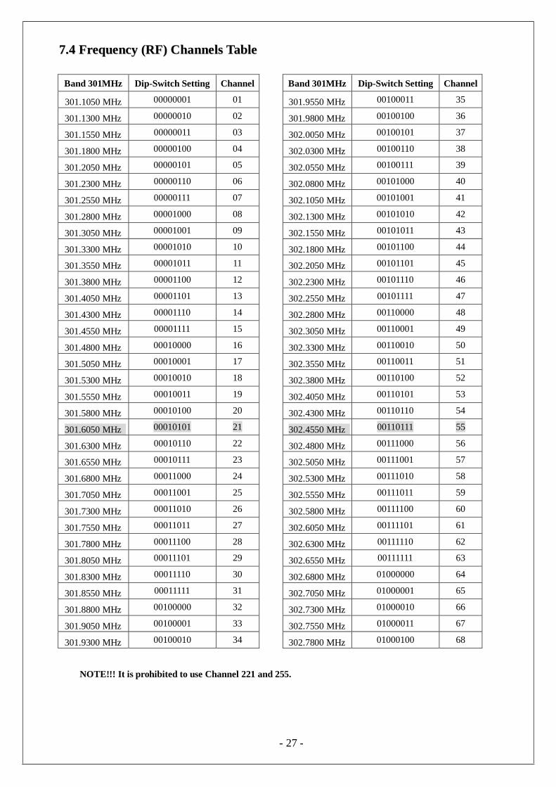
77..44 FFrreeqquueennccyy ((RRFF)) CChhaannnneellss TTaabbllee
Band 301MHz Dip-Switch Setting Channel Band 301MHz Dip-Switch Setting Channel
301.1050 MHz 00000001 01 301.9550 MHz 00100011 35
301.1300 MHz 00000010 02 301.9800 MHz 00100100 36
301.1550 MHz 00000011 03 302.0050 MHz 00100101 37
301.1800 MHz 00000100 04 302.0300 MHz 00100110 38
301.2050 MHz 00000101 05 302.0550 MHz 00100111 39
301.2300 MHz 00000110 06 302.0800 MHz 00101000 40
301.2550 MHz 00000111 07 302.1050 MHz 00101001 41
301.2800 MHz 00001000 08 302.1300 MHz 00101010 42
301.3050 MHz 00001001 09 302.1550 MHz 00101011 43
301.3300 MHz 00001010 10 302.1800 MHz 00101100 44
301.3550 MHz 00001011 11 302.2050 MHz 00101101 45
301.3800 MHz 00001100 12 302.2300 MHz 00101110 46
301.4050 MHz 00001101 13 302.2550 MHz 00101111 47
301.4300 MHz 00001110 14 302.2800 MHz 00110000 48
301.4550 MHz 00001111 15 302.3050 MHz 00110001 49
301.4800 MHz 00010000 16 302.3300 MHz 00110010 50
301.5050 MHz 00010001 17 302.3550 MHz 00110011 51
301.5300 MHz 00010010 18 302.3800 MHz 00110100 52
301.5550 MHz 00010011 19 302.4050 MHz 00110101 53
301.5800 MHz 00010100 20 302.4300 MHz 00110110 54
301.6050 MHz 00010101 21 302.4550 MHz 00110111 55
301.6300 MHz 00010110 22 302.4800 MHz 00111000 56
301.6550 MHz 00010111 23 302.5050 MHz 00111001 57
301.6800 MHz 00011000 24 302.5300 MHz 00111010 58
301.7050 MHz 00011001 25 302.5550 MHz 00111011 59
301.7300 MHz 00011010 26 302.5800 MHz 00111100 60
301.7550 MHz 00011011 27 302.6050 MHz 00111101 61
301.7800 MHz 00011100 28 302.6300 MHz 00111110 62
301.8050 MHz 00011101 29 302.6550 MHz 00111111 63
301.8300 MHz 00011110 30 302.6800 MHz 01000000 64
301.8550 MHz 00011111 31 302.7050 MHz 01000001 65
301.8800 MHz 00100000 32 302.7300 MHz 01000010 66
301.9050 MHz 00100001 33 302.7550 MHz 01000011 67
301.9300 MHz 00100010 34 302.7800 MHz 01000100 68
NOTE!!! It is prohibited to use Channel 221 and 255.

- 28 -
A
B
CD
EF
88.. TTRRAANNSSMMIITTTTEERR OOPPEERRAATTIIOONN && SSTTAATTUUSS
LLIIGGHHTT 8.1 Transmitter Operating Steps
1. Make sure the two “AA” alkaline batteries are installed correctly and battery voltage > 2.2V.
2. Battery replacement steps
A. Screw open the battery cover.
B. Pull up the ribbon (to take out the exhausted batteries)
C. & D. Put and press the first battery into the battery compartment. (Note the polarity and position)
E. & F. Put and press the second battery into the battery compartment. (Note the polarity and position)
3. Status lights: To operate the transmitter, please rotate the power key on the top-left corner clockwise
to “on” position. The status LED (green and red) will be steady “on” for 2 seconds and then “off”. If
the transmitter Status LED displays a red blinking light that is “on” 0.1 second and “off” 1.9
seconds, this indicates that the two “AA” batteries in the transmitter must be replaced.
If the transmitter Status LED is blinking red, “on” → 1.9 seconds and “off” → 0.1 second, it means
that the transmitter handset is locked due to a damaged or closed pushbutton contact. Also possibly
the operator is pressing a pushbutton while going through the start-up sequence. This important
safety feature is designed to prevent any unexpected crane movement at system startup caused by
closed or defective pushbutton contacts.
4. EMS & Restarting _ In case of an emergency, pressing down the red EMS button will send the
“Stop” command which will immediately deactivates the receiver MAIN relay.
When the red EMS button is pressed, the transmitter Status LED will display a blinking red light that
is “on” → 0.5 second and “off” → 0.5 second, telling the operator that the “Stop” command is
being sent to the receiver. On the other hand, turning the transmitter power key “off” will also
deactivate the receiver MAIN relay, but this method of MAIN relay deactivation is not recommended
in an emergency situation. For added safety, always use the red EMS button in time of an
emergency.
To reactivate the receiver MAIN relay after pressing down the red EMS button, first elevate the red
EMS button, turn the transmitter power key “off”, wait for 3 seconds until the red blinks disappeared
from the Status LED and then turn the power key back “on” again.
5. Shutting Off the Transmitter _ To disconnect the transmitter power just turn the power key to “off”
position. When the power key is switched from “on” to “off”, the transmitter will also send a “Stop”
command to the receiver for 3 seconds, the red status light flashes 3 times and at the same time
deactivate the MAIN relay.

- 29 -
6. The emergency stop button is a right-rotate momentary spring-return type. To turn on the transmitter
and activate the MAIN relay, please elevate the emergency stop button again and rotate the
transmitter power key to “ON” position.
7. Note that the transmitter cannot be hit by outer force, so that malfunction can be prevented.
8. The operating temperature is -10 ~ +60℃(±10℃). Avoid operating the transmitter in high temperature
workshop. If operating temperature is higher than 80℃, the auto shutdown protection installed inside
CPU will shut down the transmitter and deactivate the MAIN relay.
9. To operation normally, the battery power must over 2.2V. If the voltage is lower than 2.2V, the
system cannot be started and low voltage will be showed until the MAIN is completely shutdown.
10. If the power voltage is lower than 2.2V when transmitter is operated, the LV code will be “1” and low
voltage status light will be shown. For standard system, the transmitter will stop sending signals
when voltage is lower than 2.0V. But for EN ISO 13849-1 version, the transmitter will stop sending
signals when voltage is lower than 1.8V.
8.2 SMI, SSI, MSS/FSI Features
1. SMI (Select Motion Interlock) Feature
The SMI feature is programmed into all Alpha 500 Series transmitters and blocks the Select
command if any direction button is pressed. The SMI feature prevents the operator from changing
the Select state while in motion.
Direction Button Layout for North America (Left to Right):
U (PB2), D (PB1), N (PB4), S (PB3), E (PB6), W (PB5)
U (PB2), D (PB1), E (PB4), W (PB3), N (PB6), S (PB5)
Direction Button Layout Factory Default (Right to Left):
U (PB1), D (PB2), N (PB3), S (PB4), E (PB5), W (PB6)
U (PB1), D (PB2), E (PB3), W (PB4), N (PB5), S (PB6)
2. SSI (Select Safety Interlock) Feature
In addition to the above SMI feature the SSI feature can be added which blocks the Select command
unless the SAFETY/HORN button (PB11) is depressed and held first. As noted when using the SSI
feature, button (PB11) will be labeled SAFETY/HORN and in addition to interlocking the Select
command it will also control the HORN relay K14. Note that no other buttons can be depressed prior
to pressing and holding the SAFETY button. The SSI feature prevents the operator from accidentally
changing the Select state without first depressing and holding the SAFETY/HORN button and
sounding the Horn simultaneously.

- 30 -
3. MSSI/FSI (Magnet Select Safety Interlock with Fan Safety Interlock)
The MSSI/FSI is a custom program developed for cranes with a magnet On/Off circuit and magnet
Fanning. The Mag ON, Mag OFF, *FAN and SELECT I/II commands are interlocked with the
SAFETY button (PB11), and cannot be sent without first pressing and holding the Safety button. Note
that no other buttons can be depressed while pressing and holding the SAFETY button, and then you
are limited to only one command, example: press and hold SAFETY then press Mag. ON and the
magnet is turned on. To turn the magnet off release the Safety button, then press and hold the Safety
button again and press Mag. OFF and the magnet is turned off.
*The FSI feature requires the operator to press and hold the Safety button (PB11) first then press
and hold the FAN button (PB10) for 2 seconds at which time the LED lamp in the Battery On/Off
switch (top left-hand side) will flash yellow confirming the FAN command is active. With the
LED flashing the operator can Fan the magnet, lift the load (Hoist Up) or Fan the Magnet and lift
the load (Hoist Up) simultaneously. Pressing any other button while in the FSI mode will cancel
the FAN command and the LED will stop flashing.
MSSI/FSI Notes:
1. The HORN button (PB9) is not interlocked with any button.
2. The direction buttons: U & D, N & S, E & W are interlocked in pairs, that is, depressing U and

- 31 -
D simultaneously cancels both commands.
3. The direction buttons and the Mag On, Mag OFF, Fan and Safety buttons are interlocked, that
is, depressing any direction button will block these commands.
4. To enter MSSI/FSI mode, the direction buttons U, D, N, S, E, W, Magnet, Select and Fan
buttons must not be pressed. Press and hold the Safety button first, then press any one of three
buttons, Mag ON, Mag OFF or Select I/II and that command will be sent. For example, Safety
+ Mag ON = Magnet ON. To enter the FSI mode, press the Safety button first then press the
Fan button and hold both for 2 seconds, please see above explanation for *FSI feature details.
5. Only one Mag ON, Mag OFF, *FAN and SELECT I/II command will be accepted at a time.
If the operator should depress two buttons at the same time, both of the commands will be
canceled. For example, Safety + Mag On + Select I/II = no command. Please refer to point #4
for correct operation.
6. Magnet and Select button operation: All the direction, magnet, select and fan buttons must be
released first, then start again from point # 4.
7. Depressing the red e-stop button will disable the MSSI feature. To reactivate the receiver Main
relay after pressing down the red EMS button, just elevate the red EMS button and then turn
the transmitter power off and then back on again.
STOP: press → lock (emergency stop) STOP: Elevate clockwise → reset (Turn on the transmitter at any time)
8.3 Transmitter Status Light Type Status Solution LED Indication
1 Power on when voltage is
low BATT<2.2V
Red light flash ON_0.1/OFF_1.9 sec
(until power off)
2 Setting failed or invalided Set data by using
JUMPER & dip-switch
without following rules
Red light ON_0.1/OFF_0.1 sec
3 Setting completed JP1 or JP2 inserted Green light ON until power off.
4 EEPROM ID error EEPROM ID code does
not match CPU Red light ON until power off
5 RF module abnormal PLL UNLOCK Red light ON_0.1/OFF_0.1 sec
6 ID even number error Setting error Red light ON_1/OFF_1 sec
Power status
light

- 32 -
7 Pushbutton locked Power on pushbutton
connected
Red light ON_1.9/OFF_0.1 sec (until
power off)
8 Normal power on BATT>=2.2V and all the
pushbuttons are not
depressed
All the lights ON_2 sec
9 STOP status STOP button is pressed
MODE 0: Red light ON_0.5/ OFF_
0.5sec, flash 30sec.
MODE 1: all the lights OFF
10 Low voltage during
operation
BATT<2.2V and press
pushbutton Red light flash ON_0.1/OFF_1.9 sec.
11 High temperature Encoder board
temperature over 80℃
When depress button: Blinking Red light
ON_0.05/ OFF_0.15 sec.
When release button: Status light OFF
12 FSI Mode
Enable MSSI/FSI feature: press and hold
Fan + Safety buttons for
3 sec.
Red/Green lights ON_0.1/OFF_0.1 sec.
13 Normal operation Press pushbutton Green light flash ON_0.1/OFF_1.9 sec
99.. RREECCEEIIVVEERR IINNSSTTAALLLLAATTIIOONN
99..11.. PPrreeppaarraattiioonn ffoorr IInnssttaallllaattiioonn
1. Required Tools for Receiver Installation:
(1) Flat Head Screwdriver (-)
(2) Phillips Head Screwdriver (+)
(3) Multi-Meter
(4) 14mm Wrench x 2
(5) Power Drill withφ10.5mm Drill-Bit
2. Check to ensure that your receiver is not set to the same RF channel and ID code as any other systems
in operation at the same facility or within 300-meter distance.
3. Prior to installation, make sure that the crane or equipment itself is working properly.
4. Use a multi-meter to check the voltage source available and ensure the receiver voltage setting
matches your power source.
5. Prior to installation, switch off the main power source to the crane or equipment.
99..22 SStteepp bbyy SStteepp IInnssttaallllaattiioonn
1. For better reception, the location selected should have the antenna visible from all areas where the
transmitter is to be used.
2. The location selected should not be exposed to high levels of electrical noise. Mounting the receiver
next to an unshielded variable frequency control (inverter) may cause minor interference. Always

- 33 -
2 5 5 mm
2 7 8 mm
4 - O10.5
2 5 5 mm
2 7 8 mm
4 - O10.5
locate the receiver unit as far away from inverter controls as possible.
3. Ensure the selected location has adequate space to accommodate the receiver enclosure.
4. Make sure the receiver unit is in upright position (vertical).
5. The distance between the antenna and the control panel should be as far apart as possible (refer to the
fig.22 on page 40).
6. If a crane or equipment’s runway is longer than 100 meters, an external antenna should be added.
The Alpha 504i/508i receiver housing has provisions for an external factory installed antenna
available as an option, contact your dealer for price and delivery.
7. Drill a hole on the control panel (10.5mm).
8. Tightened the bolt nuts provided.
9. If the control panel has a plastic surface, extended grounding wire should be used.
10. For system wiring, please refer to the output contact diagrams from page 2.
11. Ensure all wiring is correct and safely secured and all screws are fastened.
Alpha 504i and Alpha 508i
Alpha 512i

- 34 -
99..33 SSyysstteemm TTeessttiinngg
1. Connect the power source to the receiver and test the MAIN relay output by pressing the red emergency
stop button (EMS) and observe that it properly opens and closes the main line disconnect contactor.
2. Test the operation of each function to ensure it corresponds to the transmitter direction labels and/or the
pendant it is replacing.
3. Test the limit switches on the hoist and/or crane and verify they are working properly.
4. If your new remote control is replacing an existing pendant, make sure it is completely disconnected to
prevent unwanted control commands, i.e. snick circuits.
5. If your new remote control is replacing an existing pendant make sure it is stored in a safe location
where it will not interfere with remote operation (get torn off).
9.4 Receiver system Status LED Display
FUSE
Receiver system Status LED Display
Type Led Indication Problem and Solution
1 Constant red light. EEPROM error – reprogramming required.
Incorrect receiver ID code setting (see note below).
2 ON → 1.0 second
OFF → 1.0 second
ID code not matched on both the transmitter and
receiver unit, please readjust accordingly.
3 Dim or no light. Under-voltage, check the main power-supply.
4 ON → 2.0 seconds
OFF → 0.1 second MAIN contact relay jammed or defective.
5 ON → 0.1 second
OFF → 2.0 seconds
System normal with transmitter pushbutton either in
neutral or in transmitter power “off” position.
6 ON → 0.1 second
OFF → 0.1second
System normal with transmitter pushbutton in
non-neutral position (pushbutton depressed). Note: Please refer to section 7.1 on page 22 for correct ID code setting.
LED status light

- 35 -
9.4.1 Alpha 512i Receiver System Status LED Display
Led Indication Reason Solution
Power LED display ON Normal-voltage
OFF Under-voltage
SQ, Status LED display
ON Transmitted signals detected and received
OFF No transmitting signal detected
BLINK 1.Transmitter standby Turn on the transmitter
2.Interference Turn off the transmitter
Relay LED display ON Normal operation
OFF Receiver defective Repair decoder board
1100.. TTRROOUUBBLLEE SSHHOOOOTTIINNGG
Should the operator find the equipment not operating normally, please check the chart below for simple
trouble shooting tips.
Problem Possible Reason Solution
Transmitter does
not communicate
with the receiver.
Transmitter and the receiver are
not on the same RF channel
(SQ lamp not lit) or ID code.
Ensure the correct transmitter is
in use. The labels on the receiver and the transmitter will identify the
RF channel and ID code in use.
Transmitter does not communicate
with the receiver.
Low or no transmitting power
from the transmitter unit.
Turn “on” the transmitter with EMS elevated. If the status LED
shows blinking red light or no
light at all, then turn the power “off” and replace the two alkaline
“AA” batteries.
No power to the
receiver (AC power
indicator on the receiver unit not lit).
Blown fuse or no input power
connection.
Ensure power input to the receiver
unit is correct. If the power
indicator (AC) is still not lit, please check the receiver for any open fuse.
Outputs do not
operate correctly.
Receiver configuration is not set properly or output wiring is
incorrect.
Please refer to section 6 and 7 to ensure receiver is correctly wired
and configured for your application.
Transmitter does
not communicate with the receiver.
Transmitter is turned on with the
EMS activated (pressed down).
Elevate the EMS first and then
turn the power switch off and then on again.

- 36 -
1111.. SSYYSSTTEEMM SSPPEECCIIFFIICCAATTIIOONN
Transmitter Unit
Source Voltage : Ni-MH AA size x 2 batteries 2.4V (no contact charging)
Or AA size alkaline x 2 batteries 3.0V
Antenna Impedance : Internal Antenna 50 ohms. External antenna is available.
Alpha 504i dimension : 140mm x 68mm x 30mm
Alpha 508i dimension : 189mm x 68mm x 30mm
Alpha 512i dimension : 235mm x 68mm x 30mm
Alpha 504i weight : 220g (include batteries)
Alpha 508i weight : 280g (include batteries)
Alpha 512i weight : 350g (include batteries)
Enclosure Rating : IP-65
Operating Temperature : -10℃ ~ +60℃ (> 80℃ high temperature protection)
Transmitting Power Consumption : ≦20mA@3V (Various from encoding mode and transmitting power)
≦30mA@3V(Various from encoding mode and transmitting power)
Alpha 512B /Alpha 512E-1/Alpha 512E-2
Continue Operating Time : > Consecutive 100hrs @batteries full (2000mA),
Transmitting power 1mW
LV Voltage : 2.2V – 2.0V
Transmitting RF Board Unit
Frequency Range : 301 MHz
Transmitting Power : 0.1mW – 10mW
Frequency Control : TCXO + PLL
Frequency Deviation : < 1ppm @ 25℃
Spurious Emission : < - 50dB
Emission : F1D
Antenna Impedance : 50 ohms
Operating Temperature : -10℃ ~ +60℃
Receiver Unit
Frequency Band : 301 MHz
Channel Spacing : 25KHz
Frequency Control : VTCXO (PLL)
Frequency Drift : < 5ppm @ -20℃ ~ +70℃
Frequency Deviation : < 1ppm @ 25℃
Sensitivity <-115dBm
Spurious Emission : - 50Db
Antenna Impedance : 50 ohms
Responding Time 40ms (Normal)
Enclosure Rating : IP-65
Source Voltage : α 504i/ 508i: DC12-24V, AC48V, AC110V, AC220V, AC380V,
Full voltage module AC100-240V @50/60Hz α 512i: DC12-24V, AC25/36/42/50V, AC110V/240V, AC380-460V
@50/60Hz
Power Consumption : α604: 8 Watt, α607/8: 10 Watt, α612: 15 Watt Operating Temperature : -10℃ ~ +70℃
Output Contact Rating : 250V @ 5A
Alpha 504i dimension : 310mm x 134mm x 72mm
Alpha 508i dimension : 310mm x 134mm x 72mm Alpha 512i dimension : 300mm x 230mm x 86mm
Alpha 504i weight : 1,770g (include output cable) Alpha 508i weight : 2,022g (include output cable) Alpha 512i weight : 3,500g (include output cable)

- 37 -
1122.. PPAARRTTSS LLIISSTT
Transmitter Part No.
1. Encoder board (Alpha 504A) BEN504A
Encoder board (Alpha 504B) BEN504B
Encoder board (Alpha 507A) BEN507A
Encoder board (Alpha 507B) BEN507B
Encoder board (Alpha 507AT) BEN507AT
Encoder board (Alpha 507BT) BEN507BT
Encoder board (Alpha 508A) BEN508A
Encoder board (Alpha 508B) BEN508B
Encoder board (Alpha 512A) BEN512A
Encoder board (Alpha 512B) BEN512B
Encoder board (Alpha 512C-1) BEN512C-1
Encoder board (Alpha 512C-2) BEN512C-2
Encoder board (Alpha 512D) BEN512D
Encoder board (Alpha 512E-1) BEN512E-1
Encoder board (Alpha 512E-2) BEN512E-2
2. Transmitter enclosure (Alpha 504i) BCT504
Transmitter enclosure (Alpha 507i & 508i) BCT507
Transmitter enclosure (Alpha 512i) BCT512
3. Battery cover BC600
4. 2-step pushbutton B50001
1-step pushbutton B50002
5. EMS red cap EMS01
6. EMS pushbutton mechanism (All models, red cap included) B50003
7. Pushbutton rubber fixing holder (Alpha 504i) BFH504
Pushbutton rubber fixing holder (Alpha 507i & 508i) BFH507/508
Pushbutton rubber fixing holder (Alpha 512i) BFH512
8. Pushbutton rubber boot (Alpha 504i) PRB01
Pushbutton rubber boot (Alpha 507i & 508i) PRB02
Pushbutton rubber boot (Alpha 512i) PRB03
9. Transmitter shock-absorbing rubber (All models) SAR02
10. Transmitter vinyl protective cover (Alpha 504i) VPC01
Transmitter vinyl protective cover (Alpha 507i & 508i) VPC02
Transmitter vinyl protective cover (Alpha 512i) VPC03
11. A512i waist strap WS01
12. Alkaline AA battery ALB01

- 38 -
13. A500i pushbutton direction label DL01
Receiver
1. Decoder board (Alpha 504A) BDE504A
Decoder board (Alpha 504B) BDE504B
Decoder board (Alpha 507A) BDE507A
Decoder board (Alpha 507B) BDE507B
Decoder board (Alpha 507AT) BDE507AT
Decoder board (Alpha 507BT) BDE507BT
Decoder board (Alpha 508A) BDE508A
Decoder board (Alpha 508B) BDE508B
Decoder board (Alpha 512A) BDE512A
Decoder board (Alpha 512B) BDE512B
Decoder board (Alpha 512C-1) BDE512C-1
Decoder board (Alpha 512C-2) BDE512C-2
Decoder board (Alpha 512D) BDE512D
Decoder board (Alpha 512E-1) BDE512E-1
Decoder board (Alpha 512E-2) BDE512E-2
2. 301MHz receiver RF module (All models) BRX301
3. Receiver enclosure (Alpha 504i/507i/508i) BCR507
Receiver enclosure (Alpha 512i) BCR512
4. Receiver mounting spring (Alpha 504i/507i/508i) RMS500i
5. Regular Output Contact Relay-blue (All Models) RLY01
6. Safety MAIN Contact Relay-DC12V (All Models) RLY02
7. Transformer (12/24VDC – Alpha 504i-508i) T24VDC
Transformer (24VAC – Alpha 504i-508i) T24VAC
Transformer (48VAC – Alpha 504i-508i) T48VAC
Transformer (110/120VAC – Alpha 504i-508i) T120VAC
Transformer (220/230VAC – Alpha 504i-508i) T230VAC
Transformer (380VAC – Alpha 504i-508i) T380VAC
Transformer (220/230VAC – Alpha 504i-508i) T230VAC
8. Full voltage module (100-240VAC – Alpha 504i/507i/508i) FV100-240V
9. 2-meter Output Cable with 5 Common Circuits Cable (24C*2m V3.5, Alpha 508i) OC507
10. Optional External 301 MHz Antenna (All Models) ANT301
USB programming parts
1. USB programming board (All Models) USBPCB
2. USB connecting cable (1m – All models) USBC