Embed Size (px)
Citation preview

Aalborg Universitet
Online Detection and Estimation of Grid Impedance Variation for Distributed PowerGenerationJebali-Ben Ghorbal, Manel; Ghzaiel, Walid; Slama-Belkhodja, Ilhem; Guerrero, Josep M.
Published in:Proceedings of the 16th IEEE Mediterranean Electrotechnical Conference (MELECON), 2012
DOI (link to publication from Publisher):10.1109/MELCON.2012.6196495
Publication date:2012
Document VersionEarly version, also known as pre-print
Link to publication from Aalborg University
Citation for published version (APA):Jebali-Ben Ghorbal, M., Ghzaiel, W., Slama-Belkhodja, I., & Guerrero, J. M. (2012). Online Detection andEstimation of Grid Impedance Variation for Distributed Power Generation. In Proceedings of the 16th IEEEMediterranean Electrotechnical Conference (MELECON), 2012 (pp. 555-560). IEEE Press. IEEEMediterranean Electrotechnical Conference (MELECON), proceedings, Vol.. 16, DOI:10.1109/MELCON.2012.6196495
General rightsCopyright and moral rights for the publications made accessible in the public portal are retained by the authors and/or other copyright ownersand it is a condition of accessing publications that users recognise and abide by the legal requirements associated with these rights.
? Users may download and print one copy of any publication from the public portal for the purpose of private study or research. ? You may not further distribute the material or use it for any profit-making activity or commercial gain ? You may freely distribute the URL identifying the publication in the public portal ?
Take down policyIf you believe that this document breaches copyright please contact us at [email protected] providing details, and we will remove access tothe work immediately and investigate your claim.
Downloaded from vbn.aau.dk on: maj 21, 2018

Online Detection and Estimation of Grid ImpedanceVariation for Distributed Power GenerationManel Jebali-Ben Ghorbal∗, Walid Ghzaiel†, Ilhem Slama-Belkhodja‡ and Josep M. Guerrero§
∗†‡University of Tunis El Manar, ENIT-L.S.E, BP 37-1002, Tunis le Belvedere, Tunisie∗ Email: [email protected], †Email: [email protected], ‡Email:[email protected]
§ Dept. Energy Technology, Aalborg University, 9220 Aalborg, DenmarkTechnical University of Catalonia, 08036 Barcelona, Spain, Email:[email protected]
Abstract—A better knowledge of the grid impedance is es-sential in order to improve power quality and control of theDistributed Power Generation Systems (DPGS) and also for asafe connection or reconnection to the utility grid. An LCL-filterassociated to a Voltage Source Inverter (VSI) is usually used inDPGS based on renewable energy. The VSI controller is usedto determine the grid impedance in both healthy operation andfaulty modes. When grid faults occurence, the grid impedancevariations have a considerable influence on the control and thestability of the system, even on the decision to disconnect theDPG systems of the network. This work presents a rapid andsimple technique to detect the grid impedance variation andto determine the grid impedance before and after grid faultsaccurs. Implementation on FPGA control board, simulationsand experimental results are presented to validate the describedmethod.
I. INTRODUCTION
THe Distributed Power Generation Systems (DPGS) aregaining popularity due to their contribution to feed the
grid with renewable energy. They need smart interfaces be-tween the operator and the network to improve power qualityand to satisfy the costumers need in energy. This is the reasonwhy grid information is of primer importance when connectingthe DG system to the utility network. Indeed, a grid impedancevariation has an effect on the stability of the system [1], and onthe current control loop of a Voltage Source Inverter (VSI) [2].The grid impedance information can also detect a grid failureand be useful to prevent the DG from other complications suchas the islanding operation. In the litterature,several methodswere discussed, for grid impedance variation detection or gridimpedance estimation [3], [4], [5]. These methods can beclassified into three categories:- Methods using control loop variations to estimate resistiveand inductive parts of the grid impedance to include them intothe control to improve its performances [6].- Methods using harmonic injection signal into the system,then use mathematical methods to analyse the output signal inorder to determine the grid impedance [7], [9], [12], and [13].- Methods using extra devices for the grid impedance estima-tion purpose [8].
In previous studies focusing on grid impedance calculationmethods using inter-harmonic injection signal, the grid param-eters are extracted from current and voltage responses at thepoint of common coupling (PCC). These methods complied
with hardware limitations and have the real advantage to beembeded in a PV-inverter platform. However, to obtain a goodaccuracy, the best knowledge of the background environmentis required, in order to substract background voltage noisesfrom the obtained voltage response. For this purpose, dedicatedA/D hardware devices and sensible sensors are required [14].Another work in the same field investigated an inter-harmonicvoltage injection within the digital processor instead of thegrid voltage [2]. The main drawback of this method is thatthe disturbance, repetitive or not, should be carefully chosen interms of amplitude, duration and frequency to avoid negativeeffect on the THD of the grid. Another method described in[15] discussed the variation of the inductive part of the gridimpedance Lg on the current controller, and proposed an Lgestimator by exciting the LCL-filter. However, this method didnot take into consideration the resistive part of the grid Rg .
The method presented in this paper is from the first group ofclassification methods. Its principle consists on detecting faultoccurence using temporal redundancies of current measure-ments, and then estimating the impedance variation by leadingthe system to resonance. To avoid resonance and its negativeeffect, the algorithm is stopped as soon as the resonance isreached from one hand, and from the other hand a passivedamping is used to achieve the stability of system and toreduce the effect of resonance phenomenon. Note that thereare two damping methods: passive damping consisting onadding a resistor in series with the LCL-filter capacitance andactive damping which is carried out by implementing a virtualresistor in the control strategy in order to avoid reducing theeffeciency of system.
II. PRINCIPLE OF THE PROPOSED METHOD
A. Studied system
The studied system topology is shown in Fig. 1. The grid isconnected to a pulsewidth-modulation (PWM) Voltage-SourceInverter (VSI) with a low-pass LCL-filter and the grid ispresented by a single phase sinusoidal voltage source withan impedance Zg . The impedance of the grid incorporates aresistive part Rg and an inductive part Lg . The LCL-filteris choosen especially due to its ability to operate as well inislanded mode as in grid connected mode which is a significantadvantage for DPGS applications. Besides, as with L-filter,high frequency current harmonics can be limited with the use

of the LCL-filter. The main issue to be taken into accountwhen adopting the LCL-filter solution is its resonance. It’sworth to say that the grid background disturbances has a greatimpact on the LCL resonance frequency. Indeed, this pointwas investigated in the proposed method to calculate the gridinductive part of the impedance.
Fig. 1. Grid-connected PWM-single phase inverter.
B. Grid Impedance model and principle of the method
Fig. 2. Simplified grid model.
Several grid models have been proposed in the literature[10], [11]. Each model was trying to describe the grid har-monic behavior with a different level of complexity. Forexample, the authors in [9] considered the grid as a cascadedZ-blocks. Each block involves a resistive and inductive parts,a capacitive part which presents the consumer side of thegrid and an ideal source supply denote Vs. In this work, weconsider the simplest grid model, a series inductive-resistivebranch as shown in Fig. 2. The total grid impedance is thenZg = Rg+jω.Lg and Vg is an ideal source supply. The outputVSI-voltage is denoted Vo.
The principle of the method of detection and estimation ofgrid impedance is depicted in Fig. 3. As it is detailed in thesubsection (C), the LCL-filter excitation allows the determina-tion of the grid inductance parameter Lg , then, a residual basedof current measurement is continuously caluclated. When itsvalue becomes higer than a predefined threshold, so when agrid fault is detected, the system is driven near the resonanceto perform a new caluclation of Lg parameter value. Theknwoledge of Lg value and residual measurements, before andafter fault occurence, allow to calculate grid resistance valueRg .
C. PR-controller design and grid impedance estimationmethod
First, the influence of the inductive part of the grid on theLCL filter is discussed. Fig. 4 shows the block diagram of the
Fig. 3. Principle of the proposed method.
Fig. 4. Block diagram of the grid current control loop using PR.
PR regulator where s is the Laplace operator, KPWM the gainof the inverter and TPWM the control delay. For calculationsimplifications consideration, the resistive part is neglected.The transfer function of the VSI closed loop output voltageVo to the grid current Ig can be expressed as
IgVo
=1
Lf .s.
( Rd
L2+Lgs+ Z2
f )
(s2 + ω2resCfRds+ ω2
res)(1)
being Z2f = 1
Cf (L2+Lg)
ωres =√
Lf+(L2+Lg)Lf .Cf .(L2+Lg)
(2)
From (2), the expression of the resonance frequency of theLCL filter is deduced. Hence, an increase in the inductive gridpart impedance leads to a decrease in the resonance frequencyof the LCL-filter as is shown in Fig. 5. The resonancefrequency should be of the following range
10ωg < ωres <ωPWM
2(3)
being ωg the grid frequency and ωPWM the switching fre-quency which is usually chosen between 1Khz and 20Khz.The bode plot of the transfer function from inverter outputvoltage Vo to the grid current ig (1) of Fig. 6 is drawn for twodifferent values of Lg . A first spike is shown for Lg = 1.5mHand a second one for Lg = 4.5mH .
Fig. 5. Influence of Lg variations on the resonance frequency fres.
Fig. 6. Bode diagram of the transfer function of Vo to ig
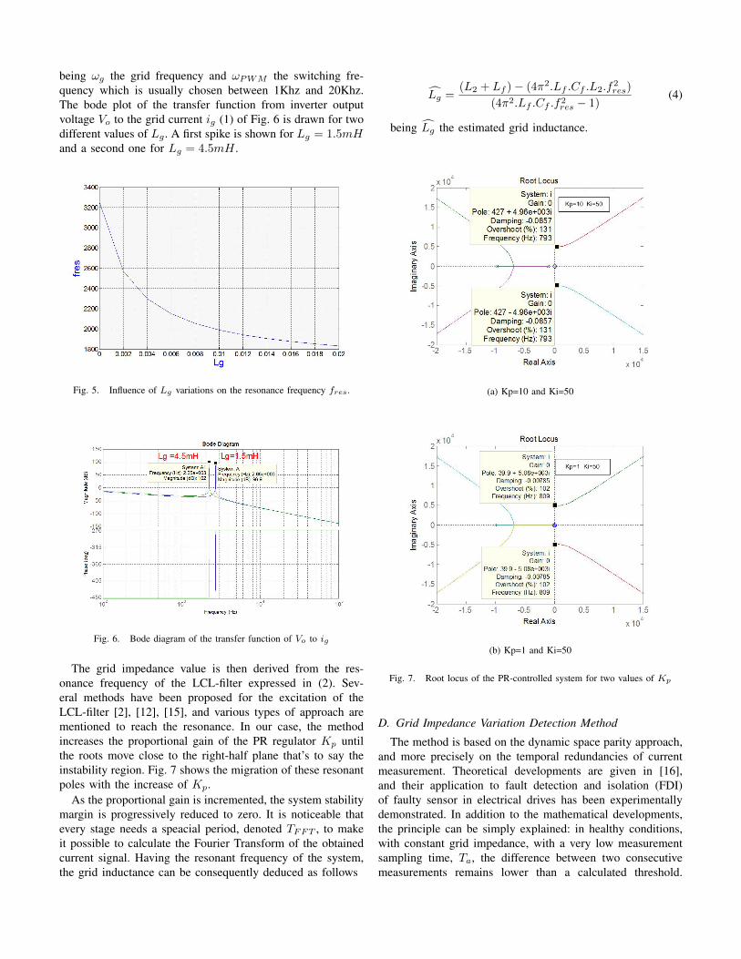
The grid impedance value is then derived from the res-onance frequency of the LCL-filter expressed in (2). Sev-eral methods have been proposed for the excitation of theLCL-filter [2], [12], [15], and various types of approach arementioned to reach the resonance. In our case, the methodincreases the proportional gain of the PR regulator Kp untilthe roots move close to the right-half plane that’s to say theinstability region. Fig. 7 shows the migration of these resonantpoles with the increase of Kp.
As the proportional gain is incremented, the system stabilitymargin is progressively reduced to zero. It is noticeable thatevery stage needs a speacial period, denoted TFFT , to makeit possible to calculate the Fourier Transform of the obtainedcurrent signal. Having the resonant frequency of the system,the grid inductance can be consequently deduced as follows
Lg =(L2 + Lf )− (4π2.Lf .Cf .L2.f
2res)
(4π2.Lf .Cf .f2res − 1)(4)
being Lg the estimated grid inductance.
(a) Kp=10 and Ki=50
(b) Kp=1 and Ki=50
Fig. 7. Root locus of the PR-controlled system for two values of Kp
D. Grid Impedance Variation Detection Method
The method is based on the dynamic space parity approach,and more precisely on the temporal redundancies of currentmeasurement. Theoretical developments are given in [16],and their application to fault detection and isolation (FDI)of faulty sensor in electrical drives has been experimentallydemonstrated. In addition to the mathematical developments,the principle can be simply explained: in healthy conditions,with constant grid impedance, with a very low measurementsampling time, Ta, the difference between two consecutivemeasurements remains lower than a calculated threshold.

When a grid impedance variation occurs, this difference in-creases and the defined residual becomes higher than thethreshold. The residual Resigk is defined by (5) and (6).
Resigk = rk + rk−1 + rk−2 (5)
rk = |igk − 2igk−1+ igk−2
| (6)
where igk , igk−1, igk−2
are the measured current at kTa,(k − 1)Ta and (k − 2)Ta respectively.
As the measured current waveform is sinusoidal, an analyt-ical expression of the maximum value of Resigk is performed[16] and leads to the threshold expressed by (7).
ε = 3ω2T 2a Im
Im =Vom−Vgm
|Zg|
(7)
with ω = 2πτs
, τs is the system time constant, Vom themaximum VSI output voltage, Vgm the maximum grid voltageand |Zg| is the grid impedance amplitude. As Lg was estimatedas explained before, Rg can be deduced using (7) as follows:
Rg =
√9ω4T 4
a
ε2(Vom − Vgm)2 − (ωLg)2 (8)
However, if the grid impedance increases or decreases, thecurrent residual measurement ResIg changes. As the residualvalue in healthy mode is denoted by εh and by εf in faultymode, the grid impedance variation is calculated as shown in(10).
|∆Z| = kfεf− khεh
(9)
|∆Z| = 3ω2T 2
a (Em − Vgm)( 1εf− 1
εh)
|∆Z| = |Zf | − |Zh|(10)
III. SIMULATIONS RESULTS
Simulations were carried out using Matlab and PSIMsoftwares. The method described above for detection andestimation of grid impedance variation is tested on a 2.5kWsingle phase inverter. The system’s parameters are given intable I. The grid resistance Rg is set to 0.673Ω and the Lg to1.5mH . The variation of the grid impedance Zg is simulatedby inserting a variable fault impedance Zd = Rd + jωLd,controlled by a switching gate block. For more clarity, inhealthy mode, the grid impedance variation is null (Zd = 0) sothe total grid impedance is equal to Zg1. Then, as the switchgate is opened, at the fault instant, the grid impedance variesaccording to (11). Fig. 8 presents the grid current evolutionas the incrementation of kp is proceeding from 17 to 31. Thefigure shows the tendency of the system to be unstable as thecurrent ig increased gradually until reaching the resonance.As can be seen, the residual value exceeds its threshold as
the resonance phenemona occurs, and presents a peak at theinstant of fault, i.e at 0.53s.
Zg = Zg1 + Zd (11)
TABLE ISYSTEM PARAMETERS
Parameter and designation valueInverter nominal power PN 2.5 kWFilter inductance Lf 6mHFilter inductance L2 2mHFilter capacitance Cf 1.6µHPower widht modulation switching frequencyfPWM 16kHzDC voltage bus VDC 450VGrid voltage Vg 230VInverter gain KPWM 1Acquisition Time Ta 5µs
Fig. 8. LCL-Resonance phenomenon of the grid current ig by the incre-mentation of kp (fault instant Tf = 0.53s).
Fig.9(a) and Fig.9(b) show the grid current residual mea-surement for two different values of Zd. In these figures, theresidual amplitude increases according the the grid impedancevariation. Nevertheless, it remains so high comparing withits value in healthy mode. The details in Fig. 10 shows thesimilarity between theory and simulations. The acquisitiontime for simulation is chosen equal to 5µs and the residualsignal lasts 4Ta = 20µs as explained in [16]. After detectinga grid fault occurance, a Fast Fourier Transformation can bedone in order to determine the resonance frequency fres. Fig.11(a) and Fig. 11(b) shows the measured grid current FFT fortwo grid impedance values. In fact, in Fig. 11(a), there is nogrid impedance variation, so the total grid inductance is equalto Zg1 . However, in Fig. 11(b), the grid impedance increasesto 3Zg1 (11). Table II gives the error of Rg and for Lg fordiffrent values of grid impedance with different X
R .

(a) Rg1 , Lg1 = 0.673Ω, 1.5mH and Zd = Zg1
(b) Rg1 , Lg1 = 0.673Ω, 1.5mH and Zd = 2Zg1
Fig. 9. Residual measurement of the grid current with Zg variation at 0.53s
TABLE IIERROR OF THE PROPOSED GRID IMPEDANCE ESTIMATION METHOD
XRratio Real Lg value Estimated Lg value Error of Lg in %
0.13 1.5 mH 1.44 mH 40.13 4.5 mH 4.40 mH 2.220.7 1.5 mH 1.47 mH 1.330.7 4.5 mH 4.42 mH 1.771.17 1.5 mH 1.47 mH 1.331.17 4.5 mH 4.47 mH 0.66
IV. EXPERIMENTAL RESULTS
The method of a grid impedance variation was tested ona three-phase-1.5kW Induction Machine. The FPGA targetdevice used is Xilinx SPARTAN3 XCS400PQ208. It has400.000 logical gates and a 50-MHz oscillator ( 20ns clockperiod).One of the three phase-current of the IM was measuredusing hall-effect sensors (LEM 25NA). An interface board
Fig. 10. Details of Fig.9 (b)
(a) FFT analysis before grid grid impedance variation (Zd = 0)
(b) Grid current FFT analysis after grid impedance variation(Zd = Zg1 )
Fig. 11. FFT analysis for ig with Rg1 = 0.673Ω and Lg1 = 1.5mH
(ARCU3I)allows the voltage level adaptation between theLEMs sensors and the ADC interface (2.5V/20A). An Anolog-Digital 12-bit-circuit (AD9221) is used for AD conversionof measured stator current, the computation time of the ac-quisition module is about 2.4µs. A 10-bits Digital-Analog(DA) converter circuit allowed viewing the current residual

measurement on a scope. In Fig. 12, experimental resultsof the current residual after a perturbation are shown. Theperturbation was set in the FPGA program of the residualcalculation. As the variation of the impedance occurs, thelevel of the residual measurement. increases and presents afranc spike. The details in Fig. 13 depict the wave form ofthe residual taht perfectly match with the simulation results.The acquisition time is set to 100µs which is higher than thereal acquisition time but it allowed a good residual viewingon the scope. Experimental results are similar to simulationsand demonstrate the effectiveness of the proposed method.
Fig. 12. Experimental result of the residual measurement of the current
Fig. 13. Details of Fig. 12
V. CONCLUSION
A novel technique for online dection and estimation ofgrid impedance variation is presented. A PR-controller fora grid connected LCL-filter inverter is proposed. Simulationsdemonstrate the reliability of the method, due to the fact thatit can be easily implemented and it respects the experimentalbackground limitations. The main features of this method isthat it gives accurate values of the impedance of the grid inboth safe and faulty modes and can operate without networkutility interruption in weak grid system. The error of theestimated inductive part of the grid is low enough to considerthe method satisfactory.
ACKNOWLEDGMENT
This work was supported by the Tunisian Ministry of HighEducation and Research under Grant LSE-ENIT-LR 11ES15.The authors would like also to acknowledge the contributionsto this project: A1/048431/11.
REFERENCES
[1] S. Yang, Q. Lei, F.Z. Peng, Z. Qian, “ A Robust Control Scheme for Grid-Connected Voltage-Source Inverters, ” IEEE transactions on IndustrialElectronics,. Vol.58, no. 1 , pp.202 -212,Jan. 2011.
[2] Guoqiao Shen,Jun Zhang,Xiao Li,Chengrui Du,Dehong Xu, “ Currentcontrol optimization for grid-tied inverters with grid impedance esti-mation, ” 2010 Twenty-Fifth Annual IEEE Applied Power ElectronicsConference and Exposition (APEC), pp.861-866, Feb. 2010.
[3] A. Moallem, D. Yazdani, A. Bakhshai, P. Jain, “Frequency domain iden-tification of the utility grid parameters for distributed power generationsystems, ” 2011 Twenty-Sixth Annual IEEE Applied Power ElectronicsConference and Exposition (APEC), pp.965-969,Mar. 2011.
[4] H. Geng, D. Xu, B. Wu, G. Yang, “ Active Islanding Detectionfor Inverter-Based Distributed Generation Systems With Power ControlInterface, ” IEEE Transactions on Energy Conversion, Vol.26, no.4,pp.1063-1072, Jul. 2011.
[5] R. Schulze, P. Schegner, ; R. Zivanovic, “ Parameter Identification ofUnsymmetrical Transmission Lines Using Fault Records Obtained FromProtective Relays, ” IEEE Transactions on Power Delivery, Vol.26, no.2 ,pp.1265-1272, Apr. 2011.
[6] A.V. Timbus, P. Rodriguez, R. Teodorescu, M. Ciobotaru, “LineImpedance Estimation Using Active and Reactive Power Variations,”IEEE, Power Electronics Specialists Conference, 2007. PESC 2007.pp.1273 - 1279, Jun. 2007.
[7] A.V. Timbus,R. Teodorescu, F. Blaabjerg, U. Borup, “ Online gridmeasurement and ENS detection for PV inverter running on highlyinductive grid, ” IEEE Power Electronics Letters, Vol.2, no. 3, pp. 77 -82, Sept. 2004.
[8] Z. Suquan, Z. Liying, Z. Yanjun, X. Yan, L. Guihua, L. Bijun, L. Lei,G. Chengming, “ A New Approach to Branch Parameter Estimation ofPower Grid Based on PMU Connected to the Grid Through an LCLFilter, ” 2011 Asia-Pacific Power and Energy Engineering Conference(APPEEC), pp.1-5, Mar. 2011.
[9] L. Asiminoaei, R. Teodorescu, F. Blaabjerg, U. Borup, “ A new methodof on-line grid impedance estimation for PV inverter, ” Nineteenth AnnualIEEE Applied Power Electronics Conference and Exposition, 2004. APEC’04, Vol.3, pp.1527-1533, Sep. 2004.
[10] M. Mata-Dumenjo, J. Sanchez-Navarro, M. Rossetti, A. Junyent-Ferre,O. Gomis-Bellmunt, “ Integrated Simulation of a Doubly fed inductiongenerator wind turbine, ” 13th European Conference on Power Electronicsand Applications, 2009. EPE ’09, Vol.3, pp.1-7, Sept. 2009.
[11] A. Tarkiainen, R. Pollanen, M. Niemela, J. Pyrhonen, “ Identification ofgrid impedance for purposes of voltage feedback active filtering, ” IEEEPower Electronics Letters, Vol.2, no. 1, pp. 6-10, Mar. 2004.
[12] L. Asiminoaei, R. Teodorescu, F. Blaabjerg, U. Borup, “ A digitalcontrolled PV-inverter with grid impedance estimation for ENS detection,” IEEE Transactions on Power Electronics, Vol.20, no. 6 ,pp. 1480 -1490, Nov. 2005.
[13] L. Asiminoaei, R. Teodorescu, F. Blaabjerg, U. Borup, “ Implementationand Test of an Online Embedded Grid Impedance Estimation Techniquefor PV Inverters, ” IEEE Transactions on Industrial Electronics, Vol.52,no. 4 ,pp. 1136-1144, Aug. 2005.
[14] B. Palethorpe, M. Sumner, D.W.P. Thomas, “Power system impedancemeasurement using a power electronic converter, ” IEEE Power Elec-tronics Letters, Vol.43, no. 5, pp. 1401-1407, Oct. 2007.
[15] M. Liserre, F. Blaabjerg, R. Teodorescu, “Grid Impedance Estimationvia Excitation of LCL -Filter Resonance, ” Proc. on Harmonics andQuality of Power, 2000, Vol.1, pp. 208-213 , 2000.
[16] H. Berriri, M.W. Naouar, I. Slama-Belkhodja, “Easy and Fast SensorFault Detection and Isolation Algorithm for Electrical Drives, ” IEEETransactions on Power Electronics, Vol.27, no. 2, pp.490-499, Apr. 2011.