Embed Size (px)
Citation preview

Aalborg Universitet
Dam Wall Detection and Tracking using a Mechanically Scanned Imaging Sonar
Kazmi, Syed Wajahat Ali Shah; Ridao, Pere; Ribas, David ; Hernandez, Emili
Published in:Robotics and Automation (ICRA): IEEE International Conference on
DOI (link to publication from Publisher):10.1109/ROBOT.2009.5152691
Publication date:2009
Document VersionAccepted author manuscript, peer reviewed version
Link to publication from Aalborg University
Citation for published version (APA):Kazmi, W., Ridao, P., Ribas, D., & Hernandez, E. (2009). Dam Wall Detection and Tracking using aMechanically Scanned Imaging Sonar. In Robotics and Automation (ICRA): IEEE International Conference on(pp. 3595–3600). Kobe, Japan: IEEE. DOI: 10.1109/ROBOT.2009.5152691
General rightsCopyright and moral rights for the publications made accessible in the public portal are retained by the authors and/or other copyright ownersand it is a condition of accessing publications that users recognise and abide by the legal requirements associated with these rights.
? Users may download and print one copy of any publication from the public portal for the purpose of private study or research. ? You may not further distribute the material or use it for any profit-making activity or commercial gain ? You may freely distribute the URL identifying the publication in the public portal ?
Take down policyIf you believe that this document breaches copyright please contact us at [email protected] providing details, and we will remove access tothe work immediately and investigate your claim.
Downloaded from vbn.aau.dk on: maj 10, 2018
Dam Wall Detection and Tracking Using a Mechanically ScannedImaging Sonar
Wajahat Kazmi, Pere Ridao, David Ribas and Emili Hernandez
Abstract— In Dam inspection tasks, an underwater robot hasto grab images while surveying the wall meanwhile maintaininga certain distance and relative orientation. This paper proposesthe use of an MSIS (Mechanically Scanned Imaging Sonar) forrelative positioning of a robot with respect to the wall. Animaging sonar gathers polar image scans from which depthimages (Range & Bearing) are generated. Depth scans are firstprocessed to extract a line corresponding to the wall (with theHough Transform), which is then tracked by means of an EKF(Extended Kalman Filter) using a static motion model and animplicit measurement equation associating the sensed pointsto the candidate line. The line estimate is referenced to therobot fixed frame and represented in polar coordinates (ρ&θ)which directly corresponds to the actual distance and relativeorientation of the robot with respect to the wall. The proposedsystem has been tested in simulation as well as in water tankconditions.
I. INTRODUCTION
This research was performed in the context of a projectfunded by the Spanish Ministry of Science and Technologywhich aims to explore the possible industrial applications ofunderwater robots such as dam, harbour and underwater ca-ble/pipe inspection. After a meeting with the civil engineersof the ENDESA power generation company in Spain, one ofthe tasks identified for dam inspection was a visual surveyof the wall in order to assess the state of the concrete and/orthe fence which protects the water inlet of the penstockgallery(an intake structure that controls water flow). Untilnow, these inspections were commonly achieved through thevisualization of a video recorded by a professional diverwithout using any geo-referencing information.
Although, over the last few years, several companies haveclaimed providing underwater robots for dam inspection, tothe best of the author’s knowledge, none of them providesan integral solution to the problem. Normally they proposethe use of small class ROVs (Remotely Operated Vehicles),working as teleoperated cameras for video recording, toreplace the professional diver who traditionally occupiedthis place. There exist few research precedents providing anadded value solution. One of the most relevant works is theROV3 system developed by the researchers of the Institut derecherche HydroQuebec (Canada) [1]. This is a small ROV,localized through an LBL (Long Base Line) system, whichmakes use of a multibeam sonar for collision avoidance. The
This research was sponsored by the European Commission through Eras-mus Mundus Scholarship (VIBOT Masters, http://www.vibot.org) program.
The authors are with the Department of Computer Engineering, Univer-sity of Girona, 17071 Girona, [email protected], [email protected],
[email protected], [email protected]
system is able to control the distance to the wall and includesseveral video cameras as well as a laser system for 2Dand 3D measurements. The COMEX and the Electricite DeFrance companies (France) developed a similar project [2]. Inthis case, an ROV manufactured by COMEX was localizedusing a 5-transponder LBL. Again, several video camerastogether with 2D (double spot) laser system were used totake measurements. During the year 2002, in collaborationwith the Research Development and Technological TransferCentre (CIFATT) IPA-Cluj, our team used the URIS robotworking as an ROV to build an image mosaic [3] of a smallarea of the wall of the Tartina Dam in the surroundings ofCluj (Romania). To the best of the author‘s knowledge, thiswas the first time that image mosaicking techniques wereapplied for dam inspection. An image mosaic gives an addedadvantage as it provides the civil engineers with a globalview of the inspection area. Unfortunately, the ROV was notlocalized and hence the resulting image mosaic was not geo-referenced.
Our current approach (Fig.1) for obtaining a geo-referenced, high resolution visual map of the wall, consistsof programming the ICTINEUAUV [4] robot to follow apre-defined survey path in front of a selected area of thewall while being localized using a dead reckoning systembased on a DVL(Doppler Velocity Log), a heading and adepth sensor. To bound the drift, a buoy equipped with aDGPS (Differential Global Positioning System), an MRU(Motion Reference Unit) and a USBL(Ultra Short Base Line)is used which provides geo-referenced position fixes, feedto the robot through an umbilical cable when available orthrough an acoustic modem otherwise. While moving alongthe wall, the robot gathers images of the wall tagged witha time stamp and synchronized with all the sensor dataincluding the navigation. As discussed in [5], in tasks such asdam survey, it is important to maintain a specified distanceand specially a certain relative orientation with respect tothe wall (usually orthogonal) in order to achieve a highresolution image mosaic. A similar problem was faced forship hull inspection as reported in [6]. In that case, theDVL was looking towards the ship’s hull and the rangereadings were used to compute the relative orientation ofthe robot with respect to the hull, while in our case, therobot is passively stable in roll and pitch and multiple rangeand bearing measurements of sonar are used to compute therobot’s relative orientation and distance in front of the damwall.
The aim of this paper is to propose, design and test, asuitable method to detect the wall of a dam, its distance and

Fig. 1. AUV orientation problem in a dam’s wall inspection task
orientation with respect to the robot. Although not discussedin this paper, these parameters will further be used for closeloop control in order to maintain a relative position duringthe survey. The proposed system works by first acquiringan acoustic image of a specified sector of the wall in frontof the robot with an MSIS. Then, that acoustic image istransformed into a range & bearing scan which is a set ofpoints compounded with the robot trajectory representing itin an initial frame of reference. After this pre-processing,a line feature is estimated by means of a standard HoughTransform but using an improved sonar model to decidewhich candidate line should be voted for by each sonarpoint. In order to further utilize sonar data for correcting thisestimate of the wall, the estimated line is used to initializean EKF based on a static motion model. Updates for everycompatible sonar point of the scan are carried out using animplicit measurement equation stating that the point belongsto the line. The system has been tested in simulation as wellas in water tank conditions. Finally, different alternativesare studied and compared in order to improve the trackingsuch as using heading updates from compass or completenavigation information from DVL to reference the sonar datato a selected frame of reference.
The paper is organized as follows. First, the sensor suiteneeded onboard is described in section II. Section III isdevoted to the description of the feature extraction andtracking. Finally the simulation environment and the resultsare reported in sections IV and V respectively, before theconclusions in section VI.
II. SENSOR SUITE
A. MiniKing Imaging Sonar (MSIS)
The MiniKing Imaging Sonar is a compact device de-signed for use in underwater applications such as obstacleavoidance and target recognition for both AUVs and ROVs.This sonar can perform scans in a 2D plane by rotating a fan-shaped sonar beam through a series of small angle steps. Itcan be programmed to cover variable sector lengths startingfrom a few degrees to a full 360o scan. In this project, it isprogrammed for a 90o sector, repetitive scan. Its fan-shapedbeam has a vertical aperture angle of 40o and a narrowhorizontal aperture of 3o.
B. Sontek Argonaut DVL
The SonTek Argonaut Doppler Velocity Log is a sensorspecially designed for AUV applications which measuresocean currents, vehicle speed over ground and through waterusing a precise 3-axis measurement system based on theDoppler shift effect. It operates at a frequency of 1500 kHzand has a range of about 15m. The velocity informationby this DVL is used to localize the robot through deadreckoning.
III. FEATURE EXTRACTION AND TRACKING
For planar structures such as walls, the intersection of thefan beam of the imaging sonar produces a 2D slice with highintensity values near the center. When the sonar beam rotates,this slice extends over the wall and forms a thick line (Fig.2).Segmenting this thick line produces a relatively concentratedzone of points which can safely be estimated to a line [7].Although dam walls are generally curved to improve thestructural resistance to the water pressure, generally, they canbe accurately represented by a line feature. This line can beinitially estimated applying the Hough Transform to a depthscan obtained after some pre-processing [8]. An improvedsonar model is used to decide a set of compatible lines thata particular sonar-point-measurement should vote for. Then,the initial line candidate computed can further be refined ina tracking process where the points extracted from the sonardata are associated to the line estimate if a compatibility testis satisfied.
Fig. 2. Sonar Image (facing wall at ≈ 4m, 90o sector, single scan)
A. Beam Segmentation and Range Detection
The log file generated by the MSIS contains one row ofdata for every beam, with columns 4 to 503 containing echointensities of a return. Keeping in mind the reflections fromrobot body itself along with reverberations from side andback walls, data from first and last few (around ten) columnsare discarded. Maximum value of intensity for every row (orbeam) is then taken as measurement corresponding to thefeatures in the environment. In this work, the range of thesonar sensor is kept at 10m with a resolution of 10cm. Thismeans every column index from 4 to 503 of the log filerepresents intensity at a range = (index-3) x 10cm
B. Sonar Model
Due to the horizontal aperture (beamwidth), a bearingcannot be related to a single point in space. Leonard-Whyte[9] and Neira et al. [10] proposed a sonar model where asonar measurement (ρS , θS) is not associated with a uniquepoint but with an arc of points with radius ρS and an apertureα being centered at the actual sonar measurement. Hence thepoints (ρSj , θ
Sj ) associated with the measurement are those
satisfying:
θS − α/2 ≤ θSj ≤ θS + α/2 ; ρSj = ρS (1)
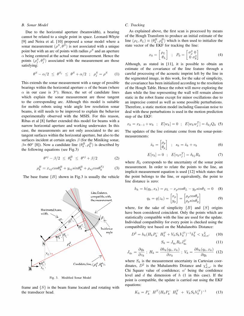
This extends the sonar measurement with a range of possiblebearings within the horizontal aperture α of the beam (whereα in our case is 3o). Hence, the set of candidate lineswhich explain the sonar measurement are those tangentto the corresponding arc. Although this model is suitablefor mobile robots using wide angle low resolution sonarbeams, it still needs to be improved to explain the behaviorexperimentally observed with the MSIS. For this reason,Ribas et al [8] further extended this model for beams with anarrow horizontal aperture and working underwater. In thiscase, the measurements are not only associated to the arctangent surfaces within the horizontal aperture, but also to thesurfaces incident at certain angles β (for the Miniking sonar,β= 60o [8]). Now a candidate line (θBk , ρ
Bk ) is described by
the following equations (see Fig.3)
θsj − β/2 ≤ θBk ≤ θsj + β/2 (2)
ρBk = xsjcosθBk + ysjsinθ
Bk + ρsjcosθ
Sjk (3)
The base frame {B} shown in Fig.3 is usually the vehicle
!
"
!
!
!
"#
" !
$
Fig. 3. Modified Sonar Model
frame and {S} is the beam frame located and rotating withthe transducer head.
C. Tracking
As explained above, the first scan is processed by meansof the Hough Transform to produce an initial estimate of theline (ρL, θL) ≡ (θBk , ρ
Bk ) which is then used to initialize the
state vector of the EKF for tracking the line:
x0 =[ρLθL
]; P0 =
[σ2ρ 0
0 σ2θ
](4)
Although, as stated in [11], it is possible to obtain anestimate of the covariance of the line feature through acareful processing of the acoustic imprint left by the line inthe segmented image, in this work, for the sake of simplicity,the covariance has been initialized according to the resolutionof the Hough Table. Hence the robot will move exploring thedam while the line representing the wall will remain almoststatic in the robot frame except for minor oscillations due toan imprecise control as well as some possible perturbations.Therefore, a static motion model including Gaussian noise todeal with these perturbations is used in the motion predictionstep of the EKF:
xk = xk−1 +wk ; E[wk] = 0 ; E[wkwTj ] = δkjQk (5)
The updates of the line estimate come from the sonar-point-measurements:
sk =[ρpθp
]; sk = sk + vk (6)
E[vk] = 0 ; E[vkvTj ] = δkjRk (7)
where Rk corresponds to the uncertainty of the sonar pointmeasurement. In order to relate the points to the line, animplicit measurement equation is used [12] which states thatthe point belongs to the line, or equivalently, the point toline distance is zero:
hk = h(qk, xk) = ρL − xpcosθL − ypsinθL = 0 (8)
qk = q(zk) =[xpyp
]=[ρpcosθpρpsinθp
](9)
where, for the sake of simplicity {B} and {S} originshave been considered coincident. Only the points which arestatistically compatible with the line are used for the update.Individual compatibility for every point is checked using thecompatibility test based on the Mahalanobis Distance:
D2 = hk(HkP−k HT
k + VkSkVTk )−1hTk < χ2
d,α′ (10)
Sk = JqkRkJ
Tqk
(11)
Jqk=∂qk∂zk
; Hk =∂hk(qk, xk)
∂xk; Vk =
∂hk(qk, xk)∂qk
(12)
where Sk is the measurement uncertainty in Cartesian coor-dinates, D2 is the Mahalanobis Distance and χ2
d,α′ is theChi Square value of confidence; α′ being the confidencelevel and d the dimension of h (1 in this case). If thepoint is compatible, the update is carried out using the EKFequations:
Kk = P−k HT (HkP−k HT
k + VkSkVTk )−1 (13)
xk = x−k −Kkhk (14)
Pk = (I −KkHk)P−k (15)
D. Integrating Heading Measurements
Heading sensors, compass and/or gyros, are commonlyavailable in ROVs and AUVs and can be used to furtherimprove the line tracking. If the absolute orientation of therobot ψWR , as well as the relative orientation of the wall withrespect to the robot θRL are known, it is possible to computethe absolute orientation of the dam βWL :
βWL = ψWR + θRL (16)
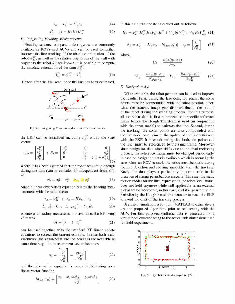
Hence, after the first scan, once the line has been estimated,
Fig. 4. Integrating Compass updates into EKF state vector
the EKF can be initialized including βWL within the statevector:
x0 =
ρWLθWLβWL
; P0 =
σ2ρ 0 0
0 σ2θ σ2
θ
0 σ2θ (σ2
θ + σ2ψ)
(17)
where it has been assumed that the robot was static enoughduring the first scan to consider θRL independent from ψWRso:
σ2β = σ2
θ + σ2ψ ; σβψ = σ2
θ (18)
Since a linear observation equation relates the heading mea-surement with the state vector:
zk = ψWR ; zk = Hxk + vk (19)
E[vk] = 0 ; E[vkvTj ] = δkjRk (20)
whenever a heading measurement is available, the followingH matrix:
H = [0 − 1 1]T (21)
can be used together with the standard KF linear updateequations to correct the current estimate. In case both mea-surements (the sonar-point and the heading) are available atsame time step, the measurement vector becomes:
qk =
ρpθpψWR
=[q(sk)ψWR
](22)
and the observation equation becomes the following non-linear vector function:
h(qk, xk) =[ρL − xpcosθL − ypsinθL
ψWR
](23)
In this case, the update is carried out as follows:
Kk = P−k HTk [HkP
−k HT + V1k
SkVT1k
+ V2kRkV
T2k
] (24)
xk = x−k +Kk[zk − h(qk, x−k )] ; zk =[
0ψWR
](25)
where,
Hk =∂hk(qk, xk)
∂xk(26)
V1k=∂hk(qk, xk)∂(ρp, θp)
; V2k=∂hk(qk, xk)
∂ψWR(27)
E. Navigation Aid
When available, the robot position can be used to improvethe results. First, during the line detection phase, the sonarpoints must be compounded with the robot position other-wise, the acoustic image gets distorted due to the motionof the robot during the scanning process. For this purpose,all the sonar data is first referenced to a specific referenceframe before the Hough Transform is used (in conjunctionwith the sonar model) to estimate the line. Second, duringthe tracking, the sonar points are also compounded withthe the robot pose prior to the update of the line estimatedwith the EKF. It is worth noting that both, the points andthe line, must be referenced to the same frame. Moreover,since navigation data often drifts due to the dead reckoningprocess, the reference frame must be changed periodically.In case no navigation data is available which is normally thecase when an ROV is used, the robot must be static duringthe line detection and moving smoothly when the tracking.Navigation data plays a particularly important role in thepresence of strong perturbations since, in this case, the staticmotion model for the line, expressed in the robot local frame,does not hold anymore while still applicable in an externalglobal frame. Moreover, in this case, still it is possible to runperiodically the Hough based line detector to reset the EKF,to avoid the drift of the tracking process.
A simple simulation is set up in MATLAB to exhaustivelytest the proposed algorithms prior to real testing with theAUV. For this purpose, synthetic data is generated for avirtual pool corresponding to the water tank dimensions usedfor field experiments
Fig. 5. Synthetic data displayed in {W}

F. Robot Motion Model
Robot motion is simulated using a 3DOF (surge, sway andyaw) constant velocity kinematic model with accelerationnoise:xyψ
Wk
=
xyψ
Wk−1
+RWR
uvr
Rk−1
∆t+
wuwvwr
Rk−1
∆t2
2
(28)
where {W} is world fixed frame located at the corner ofthe water tank, {R} is the robot fixed frame and RWR isthe rotation matrix from {R} to {W}. The vector (x, y, ψ)W
corresponds to the robot pos in the world fixed frame while(u, v, r)R and (wu, wv, wr)R are the robot velocities andthe acceleration noise respectively, both referenced to therobot frame. The robot is initialized to be at a desiredposition with some velocity. By changing the accelerationnoise it is possible to carry out experiments where the robotremains static or it hovers around a specified spot at varyingvelocities.
Fig. 6. Simulated Vs. Real environments
IV. SIMULATION ENVIRONMENT
A. Sonar Simulation
The sonar beam is simulated as a line, with its originin the transducer head, rotating at a certain speed to sweepa sector scan, repetitively. The sonar points are computedby the intersection between the sonar line and the walls ofthe rectangular water tank. The points are then corrupted inρp, θp with Gaussian noise (Fig. 5).
V. RESULTS
In this section simulations as well as experiments usingICTINEUAUV robot in the water tank of the Underwa-ter Robotics Research Center (CIRS) of the universitat deGirona are described. In both cases, results with and withoutnavigation aid are reported and discussed.
A. Simulations
Several simulations were carried out with synthetic data.A representative one is reported here. During the experiment,the robot was moving with an initial velocity (u, v, r)R =(0.3cm/s,−0.4cm/s,−0.02rad/s)Rk and acceleration noise(σu, σv, σr)Rk = (0.0008, 0.0008, 0.008)Rkm/s
2. Zero meanGaussian noise with variances σ2
ρ = (30cm)2 and σ2θ =
(5deg)2 were used to perturb the theoretical sonar reading.Fig. 7 and Fig. 8 show the tracking of the distance andorientation of the wall in front of the AUV with and without
the use of navigation information, respectively. In both thecases sonar-points and heading measurements are used forupdate during the tracking. From these figures, it is obviousthat for both the cases the ground truth stays well within 2σbounds of the estimate. Although the tracking is smootherin the case where navigation is used. On the other side,the noise added in the range is significantly large (30cm).Hence, if a 95% confidence level is used with such a noisydata, spurious measurements are also used to update theestimate which results in an erratic tracking behaviour. Ithas been observed that reducing the confidence level downto 60% makes the tracking smoother. At the same, for thecase without navigation, we cannot afford to have a verylow confidence as it reduces the number of updates andhence discardes a lot sonar data which is the only meansof correcting the wall’s relative distance and orientation.
Fig. 7. Line Tracking with navigation. In red 2σ bounds of the tracked blueline. Ground truth in green. (Synthetic Data, σrange = 30cm, σbearing =5o, Sector Size=90o, robot in Motion, 95% confidence)
Fig. 8. Line Tracking without navigation. In red 2σ bounds of thetracked blue line. Ground truth in green. (Synthetic Data, σrange = 30cm,σbearing = 5o, Sector Size=90o, robot in Motion, 95% confidence)
B. Experiments
Short duration experiments were conducted where therobot was facing a wall ≈ 4 − 5m away with slightmovements. The initial position of the wall in the robot framewas manually measured and used as the ground truth.
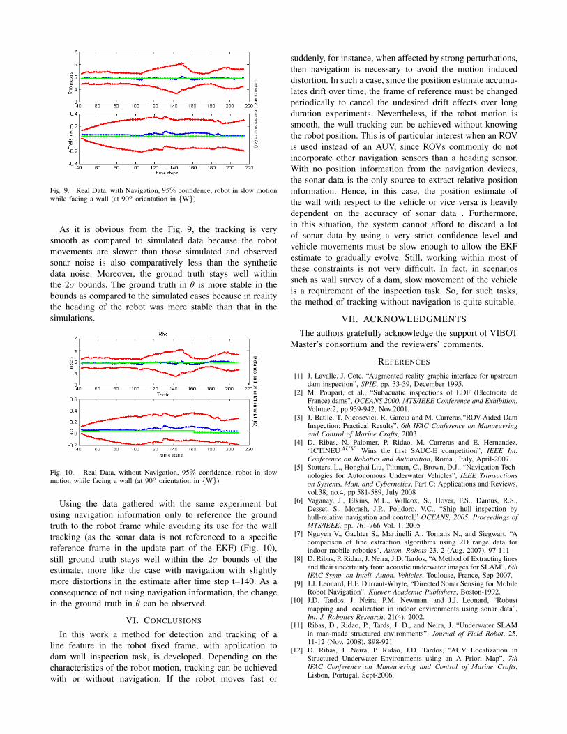
Fig. 9. Real Data, with Navigation, 95% confidence, robot in slow motionwhile facing a wall (at 90o orientation in {W})
As it is obvious from the Fig. 9, the tracking is verysmooth as compared to simulated data because the robotmovements are slower than those simulated and observedsonar noise is also comparatively less than the syntheticdata noise. Moreover, the ground truth stays well withinthe 2σ bounds. The ground truth in θ is more stable in thebounds as compared to the simulated cases because in realitythe heading of the robot was more stable than that in thesimulations.
Fig. 10. Real Data, without Navigation, 95% confidence, robot in slowmotion while facing a wall (at 90o orientation in {W})
Using the data gathered with the same experiment butusing navigation information only to reference the groundtruth to the robot frame while avoiding its use for the walltracking (as the sonar data is not referenced to a specificreference frame in the update part of the EKF) (Fig. 10),still ground truth stays well within the 2σ bounds of theestimate, more like the case with navigation with slightlymore distortions in the estimate after time step t=140. As aconsequence of not using navigation information, the changein the ground truth in θ can be observed.
VI. CONCLUSIONS
In this work a method for detection and tracking of aline feature in the robot fixed frame, with application todam wall inspection task, is developed. Depending on thecharacteristics of the robot motion, tracking can be achievedwith or without navigation. If the robot moves fast or
suddenly, for instance, when affected by strong perturbations,then navigation is necessary to avoid the motion induceddistortion. In such a case, since the position estimate accumu-lates drift over time, the frame of reference must be changedperiodically to cancel the undesired drift effects over longduration experiments. Nevertheless, if the robot motion issmooth, the wall tracking can be achieved without knowingthe robot position. This is of particular interest when an ROVis used instead of an AUV, since ROVs commonly do notincorporate other navigation sensors than a heading sensor.With no position information from the navigation devices,the sonar data is the only source to extract relative positioninformation. Hence, in this case, the position estimate ofthe wall with respect to the vehicle or vice versa is heavilydependent on the accuracy of sonar data . Furthermore,in this situation, the system cannot afford to discard a lotof sonar data by using a very strict confidence level andvehicle movements must be slow enough to allow the EKFestimate to gradually evolve. Still, working within most ofthese constraints is not very difficult. In fact, in scenariossuch as wall survey of a dam, slow movement of the vehicleis a requirement of the inspection task. So, for such tasks,the method of tracking without navigation is quite suitable.
VII. ACKNOWLEDGMENTS
The authors gratefully acknowledge the support of VIBOTMaster’s consortium and the reviewers’ comments.
REFERENCES
[1] J. Lavalle, J. Cote, “Augmented reality graphic interface for upstreamdam inspection”, SPIE, pp. 33-39, December 1995.
[2] M. Poupart, et al., “Subacuatic inspections of EDF (Electricite deFrance) dams”, OCEANS 2000. MTS/IEEE Conference and Exhibition,Volume:2, pp.939-942, Nov.2001.
[3] J. Batlle, T. Nicosevici, R. Garcia and M. Carreras,“ROV-Aided DamInspection: Practical Results”, 6th IFAC Conference on Manoeuvringand Control of Marine Crafts, 2003.
[4] D. Ribas, N. Palomer, P. Ridao, M. Carreras and E. Hernandez,“ICTINEUAUV Wins the first SAUC-E competition”, IEEE Int.Conference on Robotics and Automation, Roma., Italy, April-2007.
[5] Stutters, L., Honghai Liu, Tiltman, C., Brown, D.J., “Navigation Tech-nologies for Autonomous Underwater Vehicles”, IEEE Transactionson Systems, Man, and Cybernetics, Part C: Applications and Reviews,vol.38, no.4, pp.581-589, July 2008
[6] Vaganay, J., Elkins, M.L., Willcox, S., Hover, F.S., Damus, R.S.,Desset, S., Morash, J.P., Polidoro, V.C., “Ship hull inspection byhull-relative navigation and control,” OCEANS, 2005. Proceedings ofMTS/IEEE, pp. 761-766 Vol. 1, 2005
[7] Nguyen V., Gachter S., Martinelli A., Tomatis N., and Siegwart, “Acomparison of line extraction algorithms using 2D range data forindoor mobile robotics”, Auton. Robots 23, 2 (Aug. 2007), 97-111
[8] D. Ribas, P. Ridao, J. Neira, J.D. Tardos, “A Method of Extracting linesand their uncertainty from acoustic underwater images for SLAM”, 6thIFAC Symp. on Inteli. Auton. Vehicles, Toulouse, France, Sep-2007.
[9] J.J. Leonard, H.F. Durrant-Whyte, “Directed Sonar Sensing for MobileRobot Navigation”, Kluwer Academic Publishers, Boston-1992.
[10] J.D. Tardos, J. Neira, P.M. Newman, and J.J. Leonard, “Robustmapping and localization in indoor environments using sonar data”,Int. J. Robotics Research, 21(4), 2002.
[11] Ribas, D., Ridao, P., Tards, J. D., and Neira, J. “Underwater SLAMin man-made structured environments”. Journal of Field Robot. 25,11-12 (Nov. 2008), 898-921
[12] D. Ribas, J. Neira, P. Ridao, J.D. Tardos, “AUV Localization inStructured Underwater Environments using an A Priori Map”, 7thIFAC Conference on Maneuvering and Control of Marine Crafts,Lisbon, Portugal, Sept-2006.