Embed Size (px)
Citation preview

Aalborg Universitet
A Communication-Less Multimode Control Approach for Adaptive Power Sharing inShip-Based Seaport Microgrid
Mutarraf, Muhammad Umair; Terriche, Yacine; Nasir, Mashood; Guan, Yajuan; Lien Su ,Chun; Vasquez, Juan C.; Guerrero, Josep M.Published in:IEEE Transactions on Transportation Electrification
DOI (link to publication from Publisher):10.1109/TTE.2021.3087722
Creative Commons LicenseUnspecified
Publication date:2021
Document VersionAccepted author manuscript, peer reviewed version
Link to publication from Aalborg University
Citation for published version (APA):Mutarraf, M. U., Terriche, Y., Nasir, M., Guan, Y., Lien Su , C., Vasquez, J. C., & Guerrero, J. M. (2021). ACommunication-Less Multimode Control Approach for Adaptive Power Sharing in Ship-Based Seaport Microgrid.IEEE Transactions on Transportation Electrification, 7(4), 3070-3082. https://doi.org/10.1109/TTE.2021.3087722
General rightsCopyright and moral rights for the publications made accessible in the public portal are retained by the authors and/or other copyright ownersand it is a condition of accessing publications that users recognise and abide by the legal requirements associated with these rights.
? Users may download and print one copy of any publication from the public portal for the purpose of private study or research. ? You may not further distribute the material or use it for any profit-making activity or commercial gain ? You may freely distribute the URL identifying the publication in the public portal ?
Take down policyIf you believe that this document breaches copyright please contact us at [email protected] providing details, and we will remove access tothe work immediately and investigate your claim.

1
A Communication-less Multi-mode ControlApproach for Adaptive Power-Sharing in
Ships-based Seaport MicrogridMuhammad Umair Mutarraf, Student Member, IEEE, Yacine Terriche, Member, IEEE, Mashood
Nasir, Member, IEEE, Yajuan Guan, Member, IEEE, Chun-Lien Su,Senior Member, IEEE, Juan C. Vasquez, Senior Member, IEEE, and Josep M. Guerrero, Fellow, IEEE
Abstract—The increase in greenhouse gas emissions from thetransportation sector together with the continued depletion offossil fuels in general has encouraged an increase in the use ofenergy storage systems and renewable energy sources at seaportsand also on short route yachts and ferries. At present mostseaports, particularly smaller ones, are not provided with cold-ironing facilities – shore based power facilities, which provideelectric power to ships from the national grid. Because of thelack of cold-ironing facilities at most ports auxiliary diesel enginesand diesel generators on ships must be kept operating and onlinewhile at berth to supply auxiliary loads of ship. To address theserequirements, one possible solution would be to provide cold-ironing facilities at all ports. However, in many circumstances,this is not cost-efficient as a port might be far from the nationalgrid. To overcome these limitations a seaport microgrid can beformed through the integration of multiple shipboard microgrids(SMG) with decentralized control together with a charging in-frastructure that is located on-shore. This integration of multipleshipboard microgrids and port-based charging stations is termedas a ships-based seaport microgrid. Typically, power is shared a-mong different microgrids using data communication techniques,which adds to the cost and the complexity of the overall system.This paper proposes a communication-less approach based onmulti-mode, de-centralized droop control that enables powersharing among several SMGs in both charging and dischargingmodes based on the state of charge of battery banks – electricpower is either supplied or consumed. The proposed approachwould be potentially useful for future autonomous ships and alsofor islands where port electrification is either not technicallyfeasible or an economically viable solution. A simulation andhardware-in-the-loop results are provided to verify the controlrobustness of the proposed control strategy.
Index Terms—shipboard microgrids, power-sharing, decentral-ized droop control, mobile cold-ironing, resource balancing.
I. INTRODUCTION
Trade in the European Union (EU) is highly dependent onseaborne transportation for both intra-EU as well as global
M. U. Mutarraf, Y. Terriche, M. Nasir, Y. Guan, J. C. Vasquez and J.M. Guerrero are with the Center for Research on Microgrids (CROM),Department of Energy Technology, Aalborg University, 9220 Aalborg East,Denmark (mmu, yte, mnas, ygu, juq, joz)@et.aau.dk.
C. L. Su is with the Department of Electrical Engineering, NationalKaohsiung University of Science and Technology, Kaohsiung, Taiwan. (E-mail: [email protected])
This work was supported by VILLUM FONDEN under the VILLUMInvestigator Grant (no. 25920): Center for Research on Microgrids (CROM);www.crom.et.aau.dk. The work of Chun-Lien Su was funded by the Ministryof Science and Technology of Taiwan under Grant MOST 107-2221-E-992-073-MY3.
connectivity [1]. Seaborne transportation is not only the mostcost-effective form of transportation it also produces lowerlevels of greenhouse gas emissions in comparison with trans-portation through other modes, e.g. over land and airbornetransportation [2]. Short sea shipping accounts for one-thirdof intra-EU trade, which is crucial to the economies of theisland nations and territories of the EU [3]. At present, 37% ofintra-EU trade and 90% of the external EU trade is carried outby ships [1]. Although there are clear benefits of using shipsover land-borne or airborne transportation, emissions from theshipping sector are high and account for 2.2% of total globalemissions, which is more than the emissions from any EU state[4]. By one measure up to 2% of these emissions take placeat seaports [5]. It is anticipated that these emissions mightincrease by 150 to 250% by 2050 in comparison with 2008levels if changes to how ships are powered in port are notintroduced [6]. Any increase in seaborne trade in the comingyears will very likely lead to an increase in the number ofmarine vessels operating in the EU, and hence, an increase inpower demand during their berth-in-time results in an increasein emissions from these ships. This problem needs to beaddressed through innovative ways [7].
Alternative power sources should be considered along withenergy storage devices for both short route ships as well asfor seaports. When fossil fuel-powered ships berth at the portsthey produce emissions that are harmful to the populationliving close to these ports. One solution to the reductionof emissions from the seaports is addressed by providingpower to ships from shore power connected to the nationalgrid, which is known as cold-ironing. Although cold-ironinghelps to minimize emission from ships at berth it ultimatelyincreases the power demand on the national grid. Additionally,providing power to seaports that are far from the nationalgrid could require huge investment costs, such as buildinginfrastructure for electrification of seaports (power plants,transmission lines, substations, etc.) and therefore would notbe deemed as a feasible solution. Alternatively, we proposea shipboard microgrid (SMG) having local power generationfrom renewable energy sources (RES) on ships, which at thesame time having the ability to share power with the peer shipsin port, effectively providing mobile cold-ironing facilities.This approach could be implemented using a public-privatepartnership or by providing incentives to shipowners who ownbattery-equipped yachts or ferries. It would not only help to

2
minimize emissions from the transportation sector but wouldalso create a sustainable solution involving ports and ship-owners to contribute to the blue growth (Europe’s vision) [8].
The majority of the academic literature on this topic andexisting implementations of solutions have focused on eitherSMGs [9], [10], [11], [12] or seaport microgrids [13]. Alinkage between ports and ships is considered in [14] thatemphasizes the ship-to-grid (S2G) concept where energy istransferred for the electrification of a remote island. However,from the search of existing literature that we conductedin choosing this topic, no existing studies have consideredthe operation of SMG for use as a potential mobile cold-ironing station. To connect loads with RES, power electronics-based converters are deployed. Parallel operation of DC-DCconverters provides several benefits over an individual stand-alone converting units, as parallel operations provides recon-figurability, modular structure, redundancy, and fault tolerance[15]. The main challenge to the control system occurs whenthese converters are connected in parallel and reliability of adistributed system becomes highly dependent on the ability toshare an equal amount of power during steady-states as wellas during the transient states. Several approaches have beendescribed in the literature, such as the centralized approach[16] where the central controller is used to provide the currentreference to each converter. Another approach commonlyutilized in literature is the master-slave approach [17] thatguarantees all the slave modules to follow the current referenceof the master. Yet another approach – circular chain control(3c) is proposed in [18], which states that all the modules havethe same circuit configuration and each module has its owninner and outer loop control. In this approach, the modules arein a circular chain and each converter generates the referenceof the current for the previous one. However, existing tradi-tional current-sharing approaches rely mostly on the physicalconnection of several converter modules that compromises thereconfigurability and redundancy of the system.
Traditional power/current-sharing methods pivot on equi-table power-sharing, which can result in battery banks witha lower state of charge (SoC) to degrade and, as a resultof this, are not efficient. Because of these factors power-sharing based on droop control is proposed in [19] is attainedby varying the droop coefficient accordingly with the SoCof battery banks. The study in [20] proposes proportionalpower-sharing for DC microgrids to attain power balancingbetween several distributed sources having different SoCs.These conventional approaches all make a trade-off betweenpower/current-sharing accuracy and voltage regulation. To dealwith these problems, the study in [21] proposes the SoCbalancing approach in which the droop coefficient is set tobe inversely proportional to the SoCn in order to adjust thespeed of SoC balancing. Although this approach does achieveresource balancing during discharging mode it unfortunatelyfails to provide proportional power-sharing in charging mode.Further, using this approach – single-mode droop – in ships-based seaport microgrids, results in unnecessary power-sharingthat causes distribution losses for unwanted SoC balancing.In order to have proportional power/current sharing amongdifferent resources in both discharging and charging modes,
a multi-mode I-V droop method is proposed in [22]. Thishas the advantage in a way that the I-V droop method has abetter transient performance in comparison with the V-I droopapproach. However, stability margins for this approach arerelatively smaller in comparison with the V-I droop methodand may result in instability issues by adding up constantpower loads [23], [24]. A simplified form of the multi-modedroop approach is proposed in [25], [26], [27] but extremeconditions were not tackled in these studies and stabilityanalysis was ignored.
As a solution to the different problems of the controlmethods listed above, this paper proposes a multi-mode droopcontrol to provide a decentralized power/current-sharing a-mong various SMGs. V-I droop control works in the regionwhere SoC is between the minimum and maximum thresholdlimit, and that helps to enhance stability margins. In contrast,I-V droop mode operates in the region when SoC is belowthe minimum threshold limit or above the maximum thresholdlimit to enhance the transient response. In order to achieveresource balancing and using resources efficiently, instead ofusing fixed droop value, it is varied as a function of SoC.By applying such an approach, SMG with higher availableresources will supply the highest current whereas the leastcurrent will be shared by the SMG having the lowest SoC.
A summary of this work can be addressed as follows:1) A mobile cold-ironing approach for providing power to
ships at berth, particularly for smaller remote islandswhere electrification of the seaport is not considered asa feasible/cost-effective solution.
2) A decentralized multi-mode adaptive droop control toachieve proportional power-sharing in both charging anddischarging modes.
3) Small-signal analysis to support the stability of theproposed multi-mode algorithm.
The remainder of the paper is organized as follows: InSection II, the overall architecture of the ships-based seaportmicrogrids is described along with the adaptive droop controlstrategy. In order to know the behavior of the proposed schemewith small disturbances, a small-signal stability analysis isperformed in Section III. To support the proposed approach,case studies are taken into account and are verified throughsimulation and experimental results in Section IV. The con-clusion is presented in Section V.
II. ARCHITECTURE FOR SHIPS-BASED SEAPORTMICROGRID
The overall architecture for the proposed ship-based seaportmicrogrid scheme is illustrated in Fig. 1. This architecturehas the capability to provide both a mobile-cold ironingfacility as well as enable capability to share power amongstships. The architecture consists of several ships interfacedwith RES and battery banks, which are interconnected witheach other via charging stations placed onshore. These sourcesconsist of battery banks (lithium-ion), solar panels, and fuelcell stacks. A cold-ironing facility based on DC distributionis used in this scheme as the output of most of the RESand energy storage systems (ESS) is a DC voltage, which

3
minimizes power conversion stages. The lack of reactive powercompensation required in AC systems results in lower cost andhigher efficiency.
Fig. 1: A generic scheme of ships-based seaport microgrid[27].
A. Decentralized droop control algorithm
Multiple ships (yachts or ferries) are interconnected inparallel via charging stations onshore and any mismatch in theoutput voltage of the SMG will result in circulating currentto flow between converters. Therefore, to diminish the flowof circulating current, droop resistance is added in the outervoltage loop, which can be expressed as follows:
V o = V ref − IoRD
RD =∆V D
imax
(1)
where Vo and Io are the output voltage and current re-spectively, Vref is the reference voltage, RD is the droopresistance, ∆VD is the maximum allowable deviation, andimax corresponds to the maximum output current. In theproposed approach each SMG is interfaced with RES, i.e., fuelcell stacks or photovoltaic (PV) and battery banks, and poweris shared with the peer ships without using any communicationconnection. The droop value is varied based on the SoC of thebattery banks and bus voltage Vo, and therefore, the current-sharing for each SMG depends on the SoC. The SoC of thebattery banks can be estimated using the Coulomb countingmethod as expressed in (2).
SoCα(t) = SoCα(0) +1
Cbat
∫ T
0
V 0(I in − IL)dt (2)
where SoCα(0) is the initial SoC and Cbat is the capacityof battery (Wh). Vo and Iin refers to the voltage of bus andthe input current supplied by generation source (PV or fuelcell) respectively whereas IL is the current supplied to DCbus.
To increase the lifetime of the battery, energy balanc-ing along with optimal power-sharing is required. Power-sharing among various SMGs are classified into six modesdepending on the SoC of battery banks. These modesare assigned as: variable current-controlled charging mod-e (VCCM), i.e., 0≤SoCα<SoCmin, V-I droop mode(SoCmin≤SoCα<SoCmax), variable current-controlled dis-charging mode (VCDM), i.e., SoCmax≤SoCα≤100, and ex-treme conditions (Modes 1 and 6) as shown in Fig. 2.The maximum allowable upper (VU ) and lower (VL) voltagedeviation is set to be ±5% of the reference voltage (Vref ).
1) I-V Droop Mode–Modes 1 & 6: The first mode cor-responds to a scenario where generation sources (PV andfuel cell) are unavailable and SoC of all SMGs are belowthe threshold limit, i.e., 0 ≤ SoCα <SoCmin, which willcause bus voltage to fall below the minimum allowable voltagedeviation (Vo < VL). In order to cope with this challenge, theconstant I-V droop method is utilized such that to limit power-sharing upon such extreme conditions resulting in stabilizingDC bus voltage within allowable deviation. The referencecurrent, in this case, can be found using (3).
I ref =V L − V 0
RD(3)
Similarly, in a scenario when abundant resources are avail-able and SoC of all battery banks are above the maximumthreshold limit, i.e., SoCα>SoCmax, such a scenario willresult in an over-voltage condition (Vo > VU ), which destabi-lizes the whole system. To cater to this issue, power-sharingis limited based on the constant I-V droop method such thatVo is equivalent to VU , the reference current for such a casecan be calculated using (4).
I ref =V U − V o
RD(4)
2) VCCM–Mode 2: The second mode corresponds to VC-CM as shown in Fig. 2, this mode operates when SoCαof SMGi is below the minimum limit, i.e., 0 ≤ SoCα <SoCmin. The SMG in VCCM will start to consume powerfrom peer SMGs until SoCmin is achieved. In such a scenario,bus voltage Vo will be greater than the VL (Vo ≥ VL) indicatingthat only a few SMGs are deficient in resources. The referencecurrent for such a case can be calculated using (5). By usingsuch an approach SMG with the lowest SoC will absorb thehighest current in comparison with SMG having higher SoC.
I ref = I rat(SoCα − SoCmin
SoCmin) (5)
where Irat is the rated output current.3) V-I Droop Mode–Modes 3 & 4: Modes 3 and 4 operates
in V-I droop mode, which corresponds to a case when SoCαof the battery in certain SMG is above the minimum set valueand below the maximum set threshold value (SoCmin ≤ SoCα< SoCmax). The droop value for such a mode upon chargingand discharging can be calculated using (6)–(7) respectively.When all SMGs are in V-I droop mode, it shows that they areself-sufficient such that ships can run their internal loads inisolation, power-sharing is not required. This avoids redundant

4
Fig. 2: Multi-mode adaptive droop control algorithm.
distribution losses, therefore when all the ships have self-sufficient power the adaptive algorithms adopt (Modes 3 & 4)to ensure zero power-sharing. If a new diesel-equipped shiparrives at the port and requires connection with the mobilecold-ironing facility to power its auxiliary load, peer SMGsbased on their available resources will share the power suchthat SMG with lower SoC shares the least power as soon asthe ship is connected.
Rchar = RD(β +SoCα − SoCmin
SOCmax − SoCmin) (6)
Rdis = RD(γ − SoCα − SoCmin
SoCmax − SoCmin) (7)
where RD is the droop resistance, β = 1 and γ = 2 are thedroop coefficients. Droop resistance (RD) is varied linearlyfrom RD to 2RD and hence these values are calculated inthis manner.
4) VCDM–Mode 5: The last mode corresponds to VCDMas illustrated in Fig. 2. This is a case when the SoC is above themaximum limit, i.e., SoCα > SoCmax and Vo ≤ VU . In sucha scenario SoC of some SMGs has the value above SoCmax,which shows that they are sufficient in their resources andgeneration by RES than can be used to charge the batteriesof the nearby ships. The current reference for such a scenariocan be calculated using (8). By using such an approach, theSMG with the highest SoC will supply the highest current incomparison with SMG having the lowest SoC.
I ref = I rat(SoCα − SoCmax
100 − SoCmax) (8)
III. SMALL-SIGNAL STABILITY ANALYSIS
Small-signal stability analysis is performed to verify the sta-bility of power electronic-based converters when experiencingsmall disturbances. For instance, if a converter is subjected tosmall disturbances that cause deviation in the system variablesfor a longer period, the power system still remains stable.Generally, a charging station for an electric ship is comprisedof several stages as the power is supplied from the grid andhence, AC to DC conversion stage is needed. For our caseowing to have DC SMGs, we, therefore, required only aDC-DC conversion stage. There are several DC-DC convertertopologies used in the literature, in order to implement ourproposed method, we have taken into consideration here thesynchronous buck converter since it is simple, efficient, andreliable. The block diagram of a simplified form of a buckconverter with dual-loop control, i.e., inner current, and outervoltage-loop along with the droop control is shown in Fig. 3.The varying droop resistance is inversely proportional to theSoC of the battery, hence, changing the droop resistance variesthe SoC of the battery [28].
Fig. 3: Block diagram of the control system for single SMG[28].
The mathematical model of an average buck converter

5
model is described by expression (9)–(10).
LdiLdt
= DVg − Vo − iLRSR (9)
CdVCdt
= iL − VoRL
(10)
where Vg is the input voltage, Vo is the output voltage,D is the duty-cycle, C, L, RSR, and RL shows capacitance,inductance, stray resistance of the converter, and load attachedat the output respectively. The overall transfer function of adual-loop control of buck converter can be expressed as shownin (11).
VoDVg
=1
LCs2 + (RSRC + LRL
)s+ (1 + RSR
RL)
(11)
(a) Impact of varying SoC on the stability.
(b) Impact of varying inductance on the stability.
Fig. 4: Closed-loop eigenvalues for the system.
The control system illustrated in Fig. 3 is investigatedwith parameters: Vg = 320V , Vo = 220V , P = 2.2kW ,RD = 0.76 − 4.56Ω (0 to 100% SoC), L = 1.8 − 5.4mH , SoCmin = 30%, SoCmax = 80%, sampling time(0.0001s), C = 3300µF and RSR = 0.2Ω. The chargingstations for ships vary from several kW to MW range butthe choice of power level in the current work, i.e. 2.2 kW,is primarily made due to the maximum rating of the powerconverter available in the laboratory (Danfoss converter 2.2kW) used as a reference. It can be observed from Fig. 4
(a) that during charging mode (increasing SoC) the polesstart moving towards the left in the left half of the s-plane,which shows that system is moving towards a more stableregion while keeping L constant, i.e., 1.8mH . On the otherhand, during discharging mode the droop value decreases, andhence, poles start moving towards the right. Similarly, keepingdroop resistance constant (3.8Ω) and changing the inductance(1.8mH to 5.4mH) varies eigenvalues as shown in Fig. 4 (b).It is observed that by increasing the inductance, poles start tomove towards an unstable region.
Multiple SMG’s are connected such that power is sharedamong them by varying the droop resistances based on theSoC of the battery banks by varying the droop resistances.Hence, each SMG can either absorb or inject power to andfrom the other SMG. In order to verify the impact of variationsin the parameters on the stability of the overall system, power-sharing among two SMG’s that are connected via a tie-lineimpedance is considered as illustrated in Fig. 5 where Gidand Gvi is defined in (12). Similarly, such a model can befurther extended to verify the stability for multiple SMG’s.
Gid =VinRL
1 + sRLC
LCs2 + (RSRC + LRL
)s+ (1 + RSR
RL)
Gvi =RL
1 + sRLC
(12)
The state-space model is derived from the model in orderto know the behavior of the system upon variation in SoCof battery banks and inductances. In the first scenario, wehave considered Mode 3 and several possible eigenvalues aregenerated for the variations in SoC of SMG1 from 31 to 55%and variations in SoC of SMG2 from 58 to 79% by keepinginductance constant, i.e., 1.8mH . It can be verified from Fig.6 (a) that if the battery banks are being charged (increasingSoC) the eigenvalues in an s-plane start moving towards thefurther left side in a left-half plane, which shows the system’sstability is enhanced. On the other hand by varying SoC ofSMG1 (31 to 55%) and SMG2 (58 to 79%) along withvarying inductance from 1.8mH to 5.4mH the poles startmoving towards the right side as shown in Fig. 6 (b).
The small-signal stability analysis for a scenario whenSMG1 is in VCCM (0 ≤ SoCα < SoCmin and Vo ≥VL) corresponding to Mode 2 whereas SMG2 in V-I droopmode (SoCmin ≤ SoCα < SOCmax) corresponding to Mode3 is illustrated in Fig. 7. Although, in general, we do notdeep discharge batteries, in order to consider the worst-casescenario, we have taken the whole possible window (0 to 29%). Hence, the SoC for SMG1 is varied from 0 to 29% andSoC for SMG2 is varied from 31 to 79%, it can be observedfrom Fig. 7 that the system remains stable owing to have allpoles in the left half-plane. The single loop in VCCM helps forfaster transient response in comparison with dual-loop control.
IV. CASE STUDIES
To validate the proposed adaptive droop approach, variouscase studies are taken into consideration for simulation results,which are performed in MATLAB/SIMULINK environmen-t and experimental results in form of hardware-in-the-loop

6
Fig. 5: Block diagram of the control system for two interconnected SMG’s.
(HIL). Based on the size of the ship, the power levels ofcharging stations vary from a few kW to MWs range, while,the distribution voltage level is generally in the low voltage(LV) category.
(a) Impact of varying SoC.
(b) Impact of varying inductance.
Fig. 6: Eigenvalues for two interconnected SMGs.
To verify the proposed approach in a laboratory-scaled
environment and keeping hardware results consistent withthe simulation results, we have scaled down parameters asshown in Table I. In this study, four SMGs are taken intoaccount, which are interfaced in parallel by using a charginginfrastructure comprising of a bi-directional converting unitthus forming a DC bus. The choice of DC bus voltage in thecurrent work, i.e., 220V, is primarily made for demonstrationand validation only. This voltage level was, however, alsoadopted in some of earlier navy ships [29]. Similarly, regardingpower levels, the maximum rating of the power converteravailable in the laboratory (Danfoss converter 2.2 kW) wasused as a reference. The scheme is equally valid for relativelyhigh power and high voltage parameters.
Fig. 7: Eigenvalues for two interconnected SMGs (Modes 2& 3).
A. Simulation results
Several cases are taken into consideration and simulationresults are performed in a MATLAB/Simulink environment toverify the proposed decentralized multi-mode droop control.
1) Case 1: When one of the SMG is in VCCM: The casewhen one of the SMG is lacking in resources such that the SoCof battery banks in this case is below the minimum thresholdlimit, i.e., 0≤SoCα<SoCmin whereas the rest of SMGs arewithin minimum and maximum threshold limits. In such ascenario the SMG having lower SoC than the minimum set

7
limit begins to consume power from the nearby ships as shownin Fig. 8. The SoC of battery in each SMG in this case areassumed to be SoC1 = 5%, SoC2 = 50%, SoC3 = 65%, andSoC4 = 79%. It can be further illustrated from Fig. 8 (a)that SMG1 starts absorbing power from nearby SMGs in away that SMG with higher SoC (SMG4) supplies the highestpower in comparison with SMG having lower SoC. As one ofthe SMGs is in VCCM and hence, Vo is less than the Vref .Moreover, it can be observed from Fig. 8 (b) that SoC ofSMG4 declines the most owing to have the highest SoC.
TABLE I: Parameters for ships-based seaport microgrid.
Parameters Value Symbol
No of SMGs 4 nDC Bus Capacitance 3300 µF C
Voltage of DC bus 220 V VrefBattery Voltage 320 V VgInductance of each converter 3.6mH L
Rated power of converter 2.2kW Cc
Rated power of PV panels 1 kW PPV
Rated power of FC 5 kW PFC
Switching frequency 10 kHz fswBattery Capacity in each SMG 15 kWh CB
Rated charging current 5A IratMinimum SoC threshold limit 30% SoCmin
Maximum SoC threshold limit 80% SoCmax
Droop resistance 1.9Ω RD
(a) DC-bus voltage and current-sharing among SMGs.
(b) SoC of battery banks in different SMGs.
Fig. 8: Simulation results for the VCCM.
2) Case 2: When entire SMGs are in V-I droop mod-e: The second scenario corresponds to when entire inter-faced SMGs are above the minimum set limit (SoCmin)and below the maximum set limit (SoCmax), i.e., SoCmin≤SoCα<SoCmax. In such a case, all SMGs are self-sufficient
indicating that there will be zero power-sharing. Each shipcan run its internal loads indigenously, power-sharing is notrequired. To avoid redundant distribution losses when all theships have self-sufficient power the adaptive algorithms adopt(Modes 3 & 4) to ensure zero power-sharing. The SoC ofbattery for individual SMGs in this case are assumed to beSoC1 = 35%, SoC2 = 50%, SoC3 = 65%, and SoC4 = 79%.It can be verified from Fig. 9 (a) that the current-sharingbetween SMGs is zero and hence SoC of each battery bankin SMGs remains constant as shown in Fig. 9 (b). Moreover,owing to have zero power-sharing, the bus voltage will remainconstant and is equal to the reference voltage, i.e, 220 V. At3.75 mins, another ship, which is required with mobile cold-ironing facility connects with the main bus, each SMG startsto share power in accordance with their SoC such that SMGwith lowest SoC supplies the least current as shown in Fig. 9(a).
(a) DC-bus voltage and current-sharing among SMGs.
(b) SoC of battery banks in different SMGs.
Fig. 9: Simulation results for a V-I droop mode.
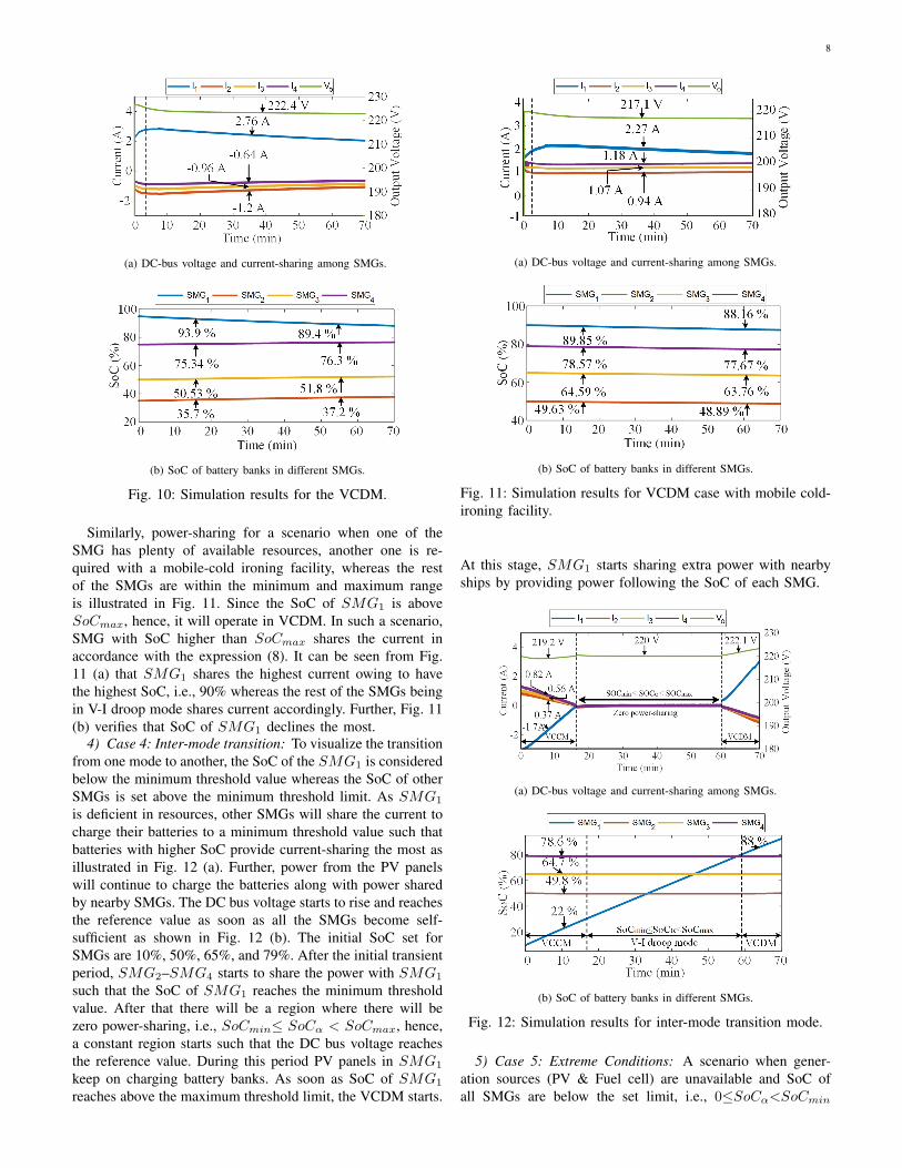
3) Case 3: When one or more of SMGs are in VCDM:Another scenario when one or more of SMGs are abundantin resources such that SoC of one or more of the SMGs areabove the maximum set limit (SoCmax), i.e., SoCα>SoCmaxis considered here, in such a scenario, Vo is greater than Vref(Vo > Vref ) as shown in Fig. 10 (a). The SoC of battery forindividual SMGs in this case are assumed to be SoC1 = 95%,SoC2 = 35%, SoC3 = 50%, and SoC4 = 75%. Since SMG1
is abundant in recourses, it starts to supply power with the peerships whereas SMG2 owing to have the lowest SoC absorbsthe highest current as illustrated in Fig. 10 (a). As soon as theSoC reaches up to the maximum set value (SoCmax), therewill be zero power-sharing. Further, it is verified from Fig. 10(b) that SMG with lower SoC absorbs the highest current andits SoC inclines the most.
8
(a) DC-bus voltage and current-sharing among SMGs.
(b) SoC of battery banks in different SMGs.
Fig. 10: Simulation results for the VCDM.
Similarly, power-sharing for a scenario when one of theSMG has plenty of available resources, another one is re-quired with a mobile-cold ironing facility, whereas the restof the SMGs are within the minimum and maximum rangeis illustrated in Fig. 11. Since the SoC of SMG1 is aboveSoCmax, hence, it will operate in VCDM. In such a scenario,SMG with SoC higher than SoCmax shares the current inaccordance with the expression (8). It can be seen from Fig.11 (a) that SMG1 shares the highest current owing to havethe highest SoC, i.e., 90% whereas the rest of the SMGs beingin V-I droop mode shares current accordingly. Further, Fig. 11(b) verifies that SoC of SMG1 declines the most.
4) Case 4: Inter-mode transition: To visualize the transitionfrom one mode to another, the SoC of the SMG1 is consideredbelow the minimum threshold value whereas the SoC of otherSMGs is set above the minimum threshold limit. As SMG1
is deficient in resources, other SMGs will share the current tocharge their batteries to a minimum threshold value such thatbatteries with higher SoC provide current-sharing the most asillustrated in Fig. 12 (a). Further, power from the PV panelswill continue to charge the batteries along with power sharedby nearby SMGs. The DC bus voltage starts to rise and reachesthe reference value as soon as all the SMGs become self-sufficient as shown in Fig. 12 (b). The initial SoC set forSMGs are 10%, 50%, 65%, and 79%. After the initial transientperiod, SMG2–SMG4 starts to share the power with SMG1
such that the SoC of SMG1 reaches the minimum thresholdvalue. After that there will be a region where there will bezero power-sharing, i.e., SoCmin≤ SoCα < SoCmax, hence,a constant region starts such that the DC bus voltage reachesthe reference value. During this period PV panels in SMG1
keep on charging battery banks. As soon as SoC of SMG1
reaches above the maximum threshold limit, the VCDM starts.
(a) DC-bus voltage and current-sharing among SMGs.
(b) SoC of battery banks in different SMGs.
Fig. 11: Simulation results for VCDM case with mobile cold-ironing facility.
At this stage, SMG1 starts sharing extra power with nearbyships by providing power following the SoC of each SMG.
(a) DC-bus voltage and current-sharing among SMGs.
(b) SoC of battery banks in different SMGs.
Fig. 12: Simulation results for inter-mode transition mode.
5) Case 5: Extreme Conditions: A scenario when gener-ation sources (PV & Fuel cell) are unavailable and SoC ofall SMGs are below the set limit, i.e., 0≤SoCα<SoCmin

9
may cause DC bus voltage to fall below the maximum lowerdeviation limit (VL) and instigate instability in the wholesystem. To cope with this challenge in an extreme scenario I-Vdroop mode is taken into account, which limits current-sharingamong different SMGs resulting in stabilizing DC bus voltageup to a value equivalent to VL (lower threshold of voltage)while limiting any further power-sharing or load fulfillment. Toverify it, initial SoC of battery banks, in this case, are assumedto be SoC1 = 5%, SoC2 = 15%, SoC3 = 20%, and SoC4 =25%. It can be observed from Fig. 13 (a) that owing to havezero power-sharing, the SoC of all SMGs remains constant andthe bus voltage remains equivalent to VL. Similarly, anotherpossibility when the SoC of all SMGs is above the maximumthreshold limit, i.e., (SoCα≥SoCmax) causes an overvoltagein the DC bus (Vo). It illustrates that batteries are charged, andexcessive generation is available due to which the bus voltagemay rise above the threshold, if not properly controlled. Hence,to stabilize the DC bus within the maximum allowable upperthreshold limit (VU ) power-sharing among different SMGs willbe limited by the I-V droop method. To verify this approach,the initial SoC of battery banks in this case are assumed to beSoC1 = 85%, SoC2 = 90%, SoC3 = 95%, and SoC4 = 100%.This sort of strategy will help to stabilize DC link voltageresulting in bus voltage equivalent to the maximum possibleupper voltage deviation limit (+5% of reference voltage). It canbe verified from Fig. 13 (b) that bus voltage remains constant,which is equivalent to the maximum possible deviation, i.e.,231 V and SoC of all SMGs remains constant. Further, in caseof excessive generation by PV in this scenario will be curtailedto stabilize the whole system.
(a) DC-bus voltage and SoC different SMGs (Mode 1).
(b) DC-bus voltage and SoC different SMGs (Mode 6).
Fig. 13: Simulation results for extreme conditions.
6) Case 6: Comparison with traditional adaptive drooptechnique: The main goal of the adaptive droop technique
proposed in our approach and the one proposed in [21]is to achieve resource balancing. Although, the convention-al adaptive approach utilized in [21] helps in proportionalpower-sharing during discharging mode but fails to achievein charging mode. Alternatively, the proposed approach pro-portionally shares power in both charging and dischargingmodes. Consider two SMGs connected in parallel where theSoC of the SMG1 is 40% and the SoC of the SMG2 is50%, which is supplied by a current-controlled source. Thesymbols I1, I2, SMG1, SMG2 illustrated in Fig. 14 areassigned to show the proposed approach whereas I3, I4,SMG3, SMG4 are used to show the approach utilized in[21]. It can be verified from Fig. 14 (a) that during chargingmode, the adaptive droop technique proposed in [21] fails toprovide proportional power-sharing and hence resources arenot balanced. Due to this, the difference between SMG3 andSMG4 keeps on increasing, on the other hand, using ourapproach, the difference between SoC1 and SoC2 decreases,hence, verifying proportional power-sharing as illustrated inFig. 14 (b).
(a) Current-sharing among SMGs.
(b) SoC of battery banks in SMGs.
Fig. 14: Comparison using our approach and the one proposedin [21].
Similarly, proportional power-sharing during charging isachieved in other modes in the proposed scheme. Consider twoSMGs connected in parallel where the SoC of the SMG1 is15% and the SoC of the SMG2 is 25%, which is supplied by acurrent-controlled source. During charging mode, if we utilizethe adaptive droop technique proposed in [21], a battery withhigher SoC (SMG2) will absorb more power in comparison tothe battery with lower SoC (SMG1) as depicted in Fig. 15 (a)and hence, resource balancing will not be achieved. Whereasin the proposed adaptive droop control, SMG with lower SoC
10
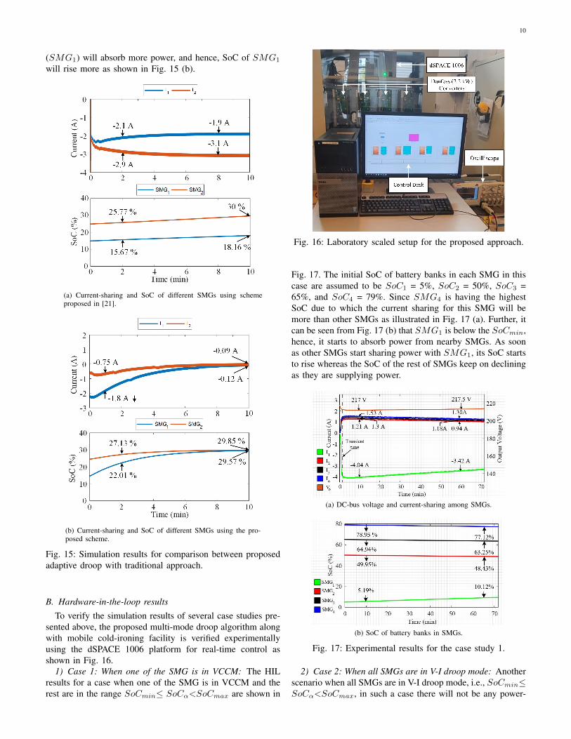
(SMG1) will absorb more power, and hence, SoC of SMG1
will rise more as shown in Fig. 15 (b).
(a) Current-sharing and SoC of different SMGs using schemeproposed in [21].
(b) Current-sharing and SoC of different SMGs using the pro-posed scheme.
Fig. 15: Simulation results for comparison between proposedadaptive droop with traditional approach.
B. Hardware-in-the-loop results
To verify the simulation results of several case studies pre-sented above, the proposed multi-mode droop algorithm alongwith mobile cold-ironing facility is verified experimentallyusing the dSPACE 1006 platform for real-time control asshown in Fig. 16.
1) Case 1: When one of the SMG is in VCCM: The HILresults for a case when one of the SMG is in VCCM and therest are in the range SoCmin≤ SoCα<SoCmax are shown in
Fig. 16: Laboratory scaled setup for the proposed approach.
Fig. 17. The initial SoC of battery banks in each SMG in thiscase are assumed to be SoC1 = 5%, SoC2 = 50%, SoC3 =65%, and SoC4 = 79%. Since SMG4 is having the highestSoC due to which the current sharing for this SMG will bemore than other SMGs as illustrated in Fig. 17 (a). Further, itcan be seen from Fig. 17 (b) that SMG1 is below the SoCmin,hence, it starts to absorb power from nearby SMGs. As soonas other SMGs start sharing power with SMG1, its SoC startsto rise whereas the SoC of the rest of SMGs keep on decliningas they are supplying power.
(a) DC-bus voltage and current-sharing among SMGs.
(b) SoC of battery banks in SMGs.
Fig. 17: Experimental results for the case study 1.
2) Case 2: When all SMGs are in V-I droop mode: Anotherscenario when all SMGs are in V-I droop mode, i.e., SoCmin≤SoCα<SoCmax, in such a case there will not be any power-

11
sharing as illustrated in Fig. 18.
(a) DC-bus voltage and current-sharing among SMGs.
(b) SoC of battery banks in SMGs.
Fig. 18: Experimental results for the case study 2.
(a) DC-bus voltage and current-sharing among SMGs.
(b) SoC of battery banks in SMGs.
Fig. 19: Experimental results for the case study 3.
It can be observed from Fig. 18 (a) that up till 3.7 minsthere is zero power-sharing such that Vo is equal to Vref andhence SoC of battery banks in all SMGs remains constant. Theinitial SoC of battery banks in each SMG, in this case, areassumed to be SoC1 = 35%, SoC2 = 50%, SoC3 = 65%, and
SoC4 = 79%. At 3.7 mins one of a diesel-based ship berthedat the seaport and is required with the mobile cold-ironingfacility, SMGs will start to share the power in accordancewith their respective SoC such that SMG4 having higher SoCshares the highest current (I4) whereas SMG1 being lowest,shares the least current (I1) as illustrated in Fig. 18 (a). Further,it can be observed from Fig. 18 (b) that SoC of SMG1 andSMG4 decreases the least and most respectively such thatall resources are efficiently used and SoC balancing will beachieved.
3) Case 3: When one of the SMG is in VCDM: A casewhen one of the SMG is abundant in resources such that theSoC of this SMG is above the maximum threshold limit, i.e.,SoCα≥SoCmax is considered here. The initial SoC of batterybanks in each SMG in this case are assumed to be SoC1 =90%, SoC2 = 79%, SoC3 = 65%, and SoC4 = 50%. To verifyexperimentally, we have taken into account that SMG1 is inVCDM whereas the rest of SMGs are in V-I droop modeproviding a mobile cold-ironing facility. It can be verifiedfrom Fig. 19 (a) that SMG1 owing to be in VCDM andhaving the highest SoC shares the highest power to a shiprequired with mobile cold-ironing facility whereas the rest ofSMGs being within the threshold hold limits, shares the powerfollowing their SoCs. Further, it is clarified from Fig. 19 (b)that SoC of SMG1 and SMG4 declines the most and theleast respectively.
(a) DC-bus voltage and current-sharing among SMGs.
(b) SoC of battery banks in SMGs.
Fig. 20: Experimental results for the case study 4.
4) Case 4: Mobile cold-ironing facility: Lastly, a casestudy is taken into consideration where all SMGs are withinthe minimum and maximum threshold limit, i.e., SoCmin≤SoCα<SoCmax and one of the newly berthed ships is con-nected and is required with the mobile cold-ironing facility.The initial SoC of battery banks in each SMG in this case

12
are assumed to be SoC1 = 35%, SoC2 = 50%, SoC3 = 65%,and SoC4 = 79%. It can be inferred from Fig. 20 (a) that thehighest current (I4) is shared by the SMG with higher SoC(SMG4) and the least current (I1) is shared by the SMG withlower SoC (SMG1). Similarly, it can be verified from Fig. 20(b) that SoC of SMG1 and SMG4 decreases the least andthe most respectively.
V. CONCLUSION
In this study, a ships-based seaport microgrid is proposed toprovide a mobile cold-ironing facility. This sort of approachis useful where providing a connection from the grid is notdeemed as a feasible solution, as building infrastructure forport electrification might not be a cost-effective solution.Further, this approach is particularly beneficial for smallerislands that have a limited source of electricity such asÆrø-island, which only relies on renewable energy resourcesmainly wind turbines. Moreover, power-sharing among variousSMGs based on a communication-less scheme is proposed,which on the basis of SoC of battery banks either absorbs orsupply the power. The proposed multi-mode adaptive droopalgorithm helps in increasing the lifetime of the battery bynot over-charging or over-discharging batteries and to attainSoC balancing in both charging and discharging modes. Thesemodes are VCCM, V-I droop mode, VCDM, and extremecondition modes. In case of an emergency, these interfacedSMGs may support the seaport by providing power fromthe battery banks, PV, and fuel cell stacks. The economicfeasibility and technical challenges including smart meteringalong with an energy management system of the proposedapproach will be addressed in the future study.
REFERENCES
[1] E. Pastori, “Modal share of freight transport to and from eu ports study,”European Parliament’s Committee on Transport and Tourism, 2015.
[2] Y. V. Fan, S. Perry, J. J. Klemes, and C. T. Lee, “A review on airemissions assessment: Transportation,” Journal of cleaner production,vol. 194, pp. 673–684, 2018.
[3] “Mobility and transport.” [Online]. Available: https://ec.europa.eu/transport/modes/maritime en.
[4] M. U. Mutarraf, Y. Terriche, M. Nasir, K. A. K. Niazi, J. C. Vasquez, andJ. M. Guerrero, “Hybrid energy storage systems for voltage stabilizationin shipboard microgrids,” in 2019 9th International Conference on Powerand Energy Systems (ICPES). IEEE, 2019, pp. 1–6.
[5] O. Merk, “Shipping emissions in ports,” 2014.[6] M. M. Rahim, M. T. Islam, and S. Kuruppu, “Regulating global shipping
corporations accountability for reducing greenhouse gas emissions in theseas,” Marine Policy, vol. 69, pp. 159–170, 2016.
[7] “The european union’s maritime transport policy for 2018.”[Online]. Available: https://ec.europa.eu/commission/presscorner/detail/de/MEMO 09 16.
[8] K. Stobberup, M. Garza-Gil, A. Stirnemann-Relot, A. Rigaud,N. Franceschelli, and R. Blomeyer, Research for PECH Committee-Small-scale fisheries and Blue Growth in the EU, 2017.
[9] Z. Jin, G. Sulligoi, R. Cuzner, L. Meng, J. C. Vasquez, and J. M. Guer-rero, “Next-generation shipboard dc power system: Introduction smartgrid and dc microgrid technologies into maritime electrical netowrks,”IEEE Electrification Magazine, vol. 4, no. 2, pp. 45–57, 2016.
[10] M. D. Al-Falahi, T. Tarasiuk, S. G. Jayasinghe, Z. Jin, H. Enshaei, andJ. M. Guerrero, “Ac ship microgrids: control and power managementoptimization,” Energies, vol. 11, no. 6, p. 1458, 2018.
[11] S. G. Jayasinghe, L. Meegahapola, N. Fernando, Z. Jin, and J. M.Guerrero, “Review of ship microgrids: System architectures, storagetechnologies and power quality aspects,” inventions, vol. 2, no. 1, p. 4,2017.
[12] M. U. Mutarraf, Y. Terriche, K. A. K. Niazi, J. C. Vasquez, and J. M.Guerrero, “Energy storage systems for shipboard microgridsa review,”Energies, vol. 11, no. 12, p. 3492, 2018.
[13] N. B. B. Ahamad, J. M. Guerrero, C.-L. Su, J. C. Vasquez, andX. Zhaoxia, “Microgrids technologies in future seaports,” in 2018 IEEEInternational Conference on Environment and Electrical Engineeringand 2018 IEEE Industrial and Commercial Power Systems Europe(EEEIC/I&CPS Europe). IEEE, 2018, pp. 1–6.
[14] K. Mahmud, M. S. Rahman, J. Ravishankar, M. J. Hossain, and J. M.Guerrero, “Real-time load and ancillary support for a remote islandpower system using electric boats,” IEEE Transactions on IndustrialInformatics, vol. 16, no. 3, pp. 1516–1528, 2019.
[15] C.-H. Cheng, P.-J. Cheng, and M.-J. Xie, “Current sharing of paralleleddc–dc converters using ga-based pid controllers,” Expert Systems withApplications, vol. 37, no. 1, pp. 733–740, 2010.
[16] A. P. Martins, A. S. Carvalho, and A. Araujo, “Design and implementa-tion of a current controller for the parallel operation of standard upss,” inProceedings of IECON’95-21st Annual Conference on IEEE IndustrialElectronics, vol. 1. IEEE, 1995, pp. 584–589.
[17] S. K. Mazumder, M. Tahir, and K. Acharya, “Master–slave current-sharing control of a parallel dc–dc converter system over an rf commu-nication interface,” IEEE Transactions on Industrial Electronics, vol. 55,no. 1, pp. 59–66, 2008.
[18] T.-F. Wu, Y.-K. Chen, and Y.-H. Huang, “3c strategy for invertersin parallel operation achieving an equal current distribution,” IEEETransactions on Industrial Electronics, vol. 47, no. 2, pp. 273–281, 2000.
[19] J. M. Guerrero, J. C. Vasquez, J. Matas, L. G. De Vicuna, and M. Castil-la, “Hierarchical control of droop-controlled ac and dc microgrids–a general approach toward standardization,” IEEE Transactions onindustrial electronics, vol. 58, no. 1, pp. 158–172, 2010.
[20] X. Lu, K. Sun, J. M. Guerrero, J. C. Vasquez, L. Huang, and R. Teodor-escu, “Soc-based droop method for distributed energy storage in dcmicrogrid applications,” in 2012 IEEE International Symposium onIndustrial Electronics. IEEE, 2012, pp. 1640–1645.
[21] X. Lu, K. Sun, J. M. Guerrero, J. C. Vasquez, and L. Huang, “State-of-charge balance using adaptive droop control for distributed energystorage systems in dc microgrid applications,” IEEE Transactions onIndustrial electronics, vol. 61, no. 6, pp. 2804–2815, 2013.
[22] M. Nasir, Z. Jin, H. A. Khan, N. A. Zaffar, J. C. Vasquez, andJ. M. Guerrero, “A decentralized control architecture applied to dcnanogrid clusters for rural electrification in developing regions,” IEEETransactions on Power Electronics, vol. 34, no. 2, pp. 1773–1785, 2018.
[23] Z. Jin, L. Meng, and J. M. Guerrero, “Comparative admittance-basedanalysis for different droop control approaches in dc microgrids,” in2017 IEEE Second International Conference on DC Microgrids (ICD-CM). IEEE, 2017, pp. 515–522.
[24] F. Gao, S. Bozhko, A. Costabeber, C. Patel, P. Wheeler, C. I. Hill, andG. Asher, “Comparative stability analysis of droop control approachesin voltage-source-converter-based dc microgrids,” IEEE Transactions onPower Electronics, vol. 32, no. 3, pp. 2395–2415, 2016.
[25] M. Nasir, M. Anees, H. A. Khan, and J. M. Guerrero, “Dual-loopcontrol strategy applied to the cluster of multiple nanogrids for ruralelectrification applications,” IET Smart Grid, vol. 2, no. 3, pp. 327–335,2019.
[26] M. Nasir, H. A. Khan, K. A. K. Niazi, Z. Jin, and J. M. Guerrero,“Dual-loop control strategy applied to pv/battery-based islanded dcmicrogrids for swarm electrification of developing regions,” The Journalof Engineering, vol. 2019, no. 18, pp. 5298–5302, 2019.
[27] M. U. Mutarraf, Y. Terriche, M. Nasir, Y. Guan, C.-L. Su, J. C. Vasquez,and J. M. Guerrero, “A decentralized control scheme for adaptive power-sharing in ships based seaport microgrid.” in IECON 2020 The 46thAnnual Conference of the IEEE Industrial Electronics Society. IEEE,2020, pp. 3126–3131.
[28] Q. Shafiee, T. Dragicevic, J. C. Vasquez, and J. M. Guerrero, “Hierar-chical control for multiple dc-microgrids clusters,” IEEE Transactionson Energy Conversion, vol. 29, no. 4, pp. 922–933, 2014.
[29] A. Burkov and G. Y. Kuvshinov, “Study of ships electrification,” in2017 International Conference on Industrial Engineering, Applicationsand Manufacturing (ICIEAM). IEEE, 2017, pp. 1–6.