Embed Size (px)
DESCRIPTION
ansys acoustic
Citation preview

© 2011 ANSYS, Inc. March 13, 2015 1
Advanced Applications
Acoustics ACTx R160

© 2011 ANSYS, Inc. March 13, 2015 2
Linear Perturbation Process

© 2014 ANSYS, Inc. March 13, 2015 3
For an acoustic-structural coupled solution, support is available for a nonlinear static structural solution using a morphed mesh under the linear perturbation scheme (modal and harmonic prestressed).
Following is the general process for solving an acoustic-structural interaction with nonlinear static structural prestress:
Linear Perturbation Process
Step Task Comments
1 Build the model The model contains either FSI interface or displacement constraints.
2 Solve a nonlinear static structural problem Perform a standard nonlinear static structural solution with the morphing operation.
3 Start a linear perturbation process Restart the solution with the linear perturbation process.
4 Solve a modal or harmonic problem Perform a modal or harmonic acoustic analysis.

© 2014 ANSYS, Inc. March 13, 2015 4
For linear perturbation process the Acoustics Body objects must be defined in the Static analysis as well as in the modal/harmonic prestressed analysis.
Also a “Perturbation Process“ object must be defined in the static analysis.
Linear Perturbation Process

© 2014 ANSYS, Inc. March 13, 2015 5
During this prestress phase the acoustics elements will be morphed in order to use properly shaped element in the downstream harmonic/modal analysis. At the “Acoustic Body” level it is thus possible to choose if the elements of the selected bodies must be morphed or not. To improve the performance of the solution one can avoid morphing elements of bodies located far from the deformed structural elements:
Linear Perturbation Process
© 2014 ANSYS, Inc. March 13, 2015 6
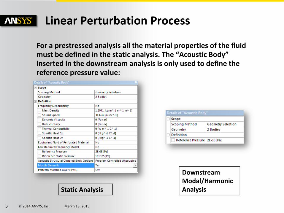
For a prestressed analysis all the material properties of the fluid must be defined in the static analysis. The “Acoustic Body” inserted in the downstream analysis is only used to define the reference pressure value:
Linear Perturbation Process
Static Analysis
Downstream Modal/Harmonic Analysis

© 2011 ANSYS, Inc. March 13, 2015 7
One Way Vibroacoustic Coupling

© 2014 ANSYS, Inc. March 13, 2015 8
One-way coupling from structure to acoustics is more computationally efficient, while the acoustic effect on the structure can be neglected. The structural results can be used as the acoustic excitation source using the one-way coupling process.
Several solutions are available for One-Way Coupling from Structure to Acoustics:
• Project Schematic Link (non-conforming mesh)
• External Data (non-conforming mesh)
• ASI File (conforming and non-conforming mesh)
One Way Vibroacoustic Coupling

© 2014 ANSYS, Inc. March 13, 2015 9
The Mechanical application allows you to apply velocities from a Structural Harmonic Response analysis as loads in an Acoustic analysis. The load transfer is applicable for the cases where the harmonic response and acoustic analyses are solved using different meshes. In this case, the velocity values are mapped and interpolated between the source and target meshes.
Drag the Solution cell of the structural system onto the Setup cell of the acoustic system.
Project Schematic link
Note: FULL and MSUP supported for structural analysis
© 2014 ANSYS, Inc. March 13, 2015 10
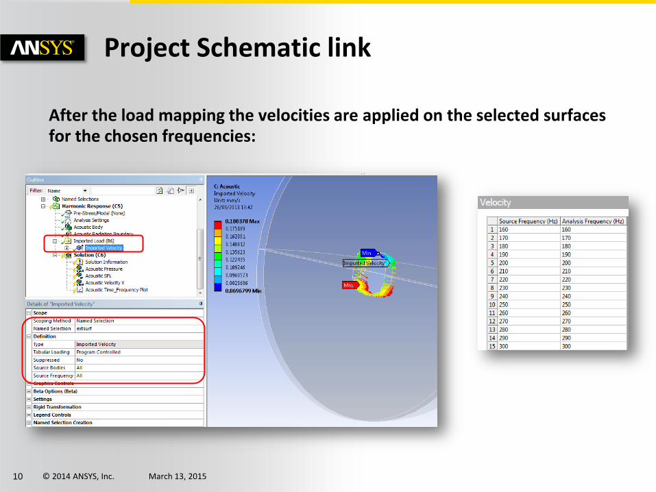
After the load mapping the velocities are applied on the selected surfaces for the chosen frequencies:
Project Schematic link

© 2014 ANSYS, Inc. March 13, 2015 11
Velocities can now be imported from text files and applied as loads in a Harmonic Response Analysis:
– Acoustics model is excited by vibration
– Uncoupled structure and acoustics are solved
– External Data component of WB converts the structure results and shares with acoustics model
– Velocity is mapped to acoustics model
External Data

© 2014 ANSYS, Inc. March 13, 2015 12
One-way Coupling via MAPDL with Multiple Frequencies or Time Steps
•Multiple Harmonic/ Transient Responses
• Full solution
•MSUP solution
Structure Model
•Nodal coordinates
•Nodal displacement (Harmonic)
•Nodal acceleration (Transient)
FSI Surface Result File: .asi • Read into mapped
results at each frequency or time step
• Acoustics Solution
Acoustics Model
SF,,FSIN,#
Using ASI one way coupling is available for harmonic and transient analyses using a conforming or nonconforming (mapping) mesh.

© 2014 ANSYS, Inc. March 13, 2015 13
A “One Way Coupling” object must be inserted
in the structural analysis:
Another “One Way Coupling” object must be inserted in the acoustic analysis:
One-way Coupling via MAPDL with Multiple Frequencies or Time Steps

© 2011 ANSYS, Inc. March 13, 2015 14
Fluent – Mechanical Coupling
© 2014 ANSYS, Inc. March 13, 2015 15
To analyze the noise inside a cavity with a vibrating wall, caused by the external turbulent flow it is required to couple Fluent results and Mechanical simulation.
Fluent allows to export in CGNS files pressure values of a transient turbulent run after its transformation in the frequency domain (for more information regarding the procedure allowing to create the CGNS files please refer to the appropriate workshop).
The CGNS files can be used in Mechanical to map the pressure of the structural component at each frequencies in harmonic response analyses.
Fluent – Mechanical Coupling

© 2014 ANSYS, Inc. March 13, 2015 16
The “Full” harmonic resolution method must be chosen here because this is currently the only solution method supported to import and map the CFD pressure from the CGNS files.
It is also worth noting that the “Frequency Spacing” and “Solution Intervals” values aren’t important here because they will be ignored during the solution. Indeed when CGNS files are imported, the solver performs the resolution for all frequencies between the “Range Minimum” and the “Range Maximum” contained in those files.
Analysis Settings

© 2014 ANSYS, Inc. March 13, 2015 17
Insert a “CFD Pressure mapping” object in the harmonic analysis from the “Tools” menu of the “Acoustics” toolbar.
Then select the faces of the plate on which the pressure will be mapped and select the cgns files (refer to AACTx_R160_WS14 - Windshield Noise (Fluent coupling).docx to see how to create the cgns files in Fluent).
Pressure Mapping
Note: Refer to FLUREAD MAPDL command for more information

© 2014 ANSYS, Inc. March 13, 2015 18
In postprocessing it is possible to display the mapped pressure at a given frequency.
If you want to plot it you need to request to save the “General Miscellaneous” output in the analysis settings:
Mapped Pressure Postprocessing

© 2014 ANSYS, Inc. March 13, 2015 19
Insert a “Fluent Mapped Pressure” result from “Results” menu of the Acoustics toolbar to plot the real and imaginary components of the mapped pressure at a given frequency:
Mapped Pressure Postprocessing


![T150-R160 (Generic 6SW) Manualcoopercrouse-hinds.com/content/dam/public/bussmann/Wireless/Re… · ESTOP FAULT LINK STATUS 1. Opening the R160 Case A. Press [E-Stop] B. Twist Clockwise](https://img.dokumen.tips/doc/110x75/6144ff7134130627ed50b495/t150-r160-generic-6sw-manualcoopercrouse-hindscomcontentdampublicbussmannwirelessre.jpg)