Embed Size (px)
Citation preview

1
A75M-HVS
User Manual
Version 1.1Published June 2011
Copyright©2011 ASRock INC. All rights reserved.

1
Engl
ish
Copyright Notice:No part of this installation guide may be reproduced, transcribed, transmitted, or trans-lated in any language, in any form or by any means, except duplication of documentation by the purchaser for backup purpose, without written consent of ASRock Inc.Products and corporate names appearing in this guide may or may not be registered trademarks or copyrights of their respective companies, and are used only for identifica-tion or explanation and to the owners’ benefit, without intent to infringe.
Disclaimer:Specifications and information contained in this guide are furnished for informational use only and subject to change without notice, and should not be constructed as a commit-ment by ASRock. ASRock assumes no responsibility for any errors or omissions that may appear in this guide. With respect to the contents of this guide, ASRock does not provide warranty of any kind, either expressed or implied, including but not limited to the implied warranties or condi-tions of merchantability or fitness for a particular purpose. In no event shall ASRock, its directors, officers, employees, or agents be liable for any indirect, special, incidental, or consequential damages (including damages for loss of profits, loss of business, loss of data, interruption of business and the like), even if ASRock has been advised of the pos-sibility of such damages arising from any defect or error in the guide or product.
This device complies with Part 15 of the FCC Rules. Operation is subject to the following two conditions: (1) this device may not cause harmful interference, and (2) this device must accept any interference received, including interference that
may cause undesired operation.
CALIFORNIA, USA ONLYThe Lithium battery adopted on this motherboard contains Perchlorate, a toxic substance controlled in Perchlorate Best Management Practices (BMP) regulations passed by the California Legislature. When you discard the Lithium battery in California, USA, please follow the related regulations in advance.“Perchlorate Material-special handling may apply, see www.dtsc.ca.gov/hazardouswaste/perchlorate”
The terms HDMI™ and HDMI High-Definition Multimedia Interface, and the HDMI logo are trademarks or registered trademarks of HDMI Licensing LLC in the United States and other countries.

3
Contents1. Introduction ................................................................. 5 1.1 Package Contents ..................................................................... 5 1.2 Specifications ............................................................................. 6 1.3 Motherboard Layout ................................................................. 11 1.4 I/O Panel .................................................................................. 12
2. Installation ................................................................... 13 Pre-installation Precautions ................................................................ 13 2.1 CPU Installation ......................................................................... 14 2.2 Installation of CPU Fan and Heatsink ...................................... 14 2.3 Installation of Memory Modules (DIMM) .................................... 15 2.4 Expansion Slots (PCI and PCI Express Slots) ........................... 16 2.5 Dual Graphics Operation Guide ................................................ 17 2.6 Dual Monitor and Surround Display Features ........................... 19 2.7 ASRock Smart Remote Installation Guide ................................. 22 2.8 Jumpers Setup ........................................................................... 23 2.9 Onboard Headers and Connectors ....................................... 24 2.10 Serial ATA3 (SATA3) Hard Disks Installation ......................... 28 2.11 Hot Plug and Hot Swap Functions for SATA3 HDDs ................. 28 2.12 SATA3 HDD Hot Plug and Hot SwapFeature and Operation Operation Guide ........................................................................ 29 2.13 Driver Installation Guide ............................................................ 31 2.14 Installing Windows® 7 / 7 64-bit / VistaTM / VistaTM 64-bit / XP / XP 64-bit With RAID Functions .................................................. 31 2.14.1 Installing Windows® XP / XP 64-bit With RAID Functions ....................................................................... 31 2.14.2 Installing Windows® 7 / 7 64-bit / VistaTM / VistaTM 64-bit With RAID Functions ..................................................... 32 2.15 Installing Windows® 7 / 7 64-bit / VistaTM / VistaTM 64-bit / XP / XP 64-bit Without RAID Functions ............................................. 33 2.15.1 Installing Windows® XP / XP 64-bit Without RAID Functions ....................................................................... 33 2.15.2 Installing Windows® 7 / 7 64-bit / VistaTM / VistaTM 64-bit Without RAID Functions ................................................ 34
4
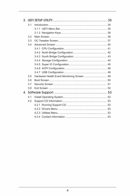
3. UEFI SETUP UTILITY.......................................................... 35 3.1 Introduction ................................................................................ 35 3.1.1 UEFI Menu Bar ................................................................ 35 3.1.2 Navigation Keys ............................................................... 36 3.2 Main Screen ............................................................................... 36 3.3 OC Tweaker Screen................................................................... 37 3.4 Advanced Screen ...................................................................... 40 3.4.1 CPU Configuration ........................................................... 41 3.4.2 North Bridge Configuration .............................................. 42 3.4.3 South Bridge Configuration ............................................. 43 3.4.4 Storage Configuration ...................................................... 44 3.4.5 Super IO Configuration .................................................... 45 3.4.6 ACPI Configuration .......................................................... 46 3.4.7 USB Configuration ........................................................... 48 3.5 Hardware Health Event Monitoring Screen ............................... 49 3.6 Boot Screen ............................................................................... 50 3.7 Security Screen ......................................................................... 51 3.8 Exit Screen ................................................................................ 52
4. Software Support ......................................................... 53 4.1 Install Operating System ............................................................ 53 4.2 Support CD Information ............................................................. 53 4.2.1 Running Support CD ....................................................... 53 4.2.2 Drivers Menu ................................................................... 53 4.2.3 Utilities Menu ................................................................... 53 4.2.4 Contact Information ......................................................... 53

5
1. IntroductionThank you for purchasing ASRock A75M-HVS motherboard, a reliable motherboard produced under ASRock’s consistently stringent quality control. It delivers excellent performance with robust design conforming to ASRock’s commitment to quality and endurance.In this manual, chapter 1 and 2 contain introduction of the motherboard and step-by-step guide to the hardware installation. Chapter 3 and 4 contain the configuration guide to BIOS setup and information of the Support CD.
Because the motherboard specifications and the BIOS software might be updated, the content of this manual will be subject to change without notice. In case any modifications of this manual occur, the updated ver-sion will be available on ASRock website without further notice. You may find the latest VGA cards and CPU support lists on ASRock website as well. ASRock website http://www.asrock.com
If you require technical support related to this motherboard, please visit our website for specific information about the model you are using.www.asrock.com/support/index.asp
1.1 Package ContentsASRock A75M-HVS Motherboard (Micro ATX Form Factor: 8.9-in x 8.5-in, 22.6 cm x 21.6 cm)ASRock A75M-HVS Quick Installation GuideASRock A75M-HVS Support CD2 x Serial ATA (SATA) Data Cables (Optional)1 x I/O Panel Shield
ASRock Reminds You...To get better performance in Windows® 7 / 7 64-bit / VistaTM / VistaTM 64 bit, it is recommended to set the BIOS option in Storage Configuration to AHCI mode. For the BIOS setup, please refer to the “User Manual” in our support CD for details.

6
1.2 Specifications
Platform - Micro ATX Form Factor: 8.9-in x 8.5-in, 22.6 cm x 21.6 cm - Solid Capacitor for CPU power CPU - Support for Socket FM1 100W processors - Supports AMD’s Cool ‘n’ QuietTM Technology - UMI-Link GEN2 Chipset - AMD A75 FCH (Hudson-D3) Memory - Dual Channel DDR3 Memory Technology (see CAUTION 1) - 2 x DDR3 DIMM slots - Support DDR3 2400+(OC)/1866/1600/1333/ 1066/800 non-ECC, un-buffered memory (see CAUTION 2) - Max. capacity of system memory: 16GB (see CAUTION 3) Expansion Slot - 1 x PCI Express 2.0 x16 slot - 1 x PCI Express 2.0 x1 slot - 1 x PCI slot - Supports AMD Dual Graphics Graphics - AMD Radeon HD 65XX/64XX graphics - DirectX 11, Pixel Shader 5.0 - Max. shared memory 512MB (see CAUTION 4) - Dual VGA Output: support HDMI and D-Sub ports by independent display controllers - Supports HDMI 1.4a Technology with max. resolution up to 1920x1200 @ 60Hz - Supports D-Sub with max. resolution up to 1920x1600 @ 60Hz - Supports Auto Lip Sync, Deep Color (12bpc), xvYCC and HBR (High Bit Rate Audio) with HDMI (Compliant HDMI monitor is required) (see CAUTION 5) - Supports Blu-ray Stereoscopic 3D with HDMI 1.4a - Supports AMD Steady VideoTM: New video post processing capability for automatic jutter reduction on home/online video - Supports HDCP function with HDMI port - Supports Full HD 1080p Blu-ray (BD) / HD-DVD playback with HDMI port Audio - 5.1 CH HD Audio (VIA® VT1705 Audio Codec) - Supports THX TruStudioTM LAN - PCIE x1 Gigabit LAN 10/100/1000 Mb/s - Realtek RTL8111E - Supports Wake-On-LAN

7
- Supports LAN Cable Detection - Supports Energy Efficient Ethernet 802.3az - Supports PXE Rear Panel I/O I/O Panel - 1 x PS/2 Mouse Port - 1 x PS/2 Keyboard Port - 1 x D-Sub Port - 1 x HDMI Port - 2 x Ready-to-Use USB 2.0 Ports - 4 x Ready-to-Use USB 3.0 Ports - 1 x RJ-45 LAN Port with LED (ACT/LINK LED and SPEED LED) - HD Audio Jack: Line in/Front Speaker/Microphone SATA3 - 6 x SATA3 6.0 Gb/s connectors, support RAID (RAID 0, RAID 1 and RAID 10), NCQ, AHCI and “Hot Plug” functions USB 3.0 - 4 x USB 3.0 ports, support USB 1.0/2.0/3.0 up to 5Gb/s Connector - 6 x SATA3 6.0Gb/s connectors - 1 x IR header - 1 x CIR header - 1 x Print port header - 1 x COM port header - CPU/Chassis/Power FAN connector - 24 pin ATX power connector - 8 pin 12V power connector - Front panel audio connector - 3 x USB 2.0 headers (support 6 USB 2.0 ports) BIOS Feature - 32Mb AMI UEFI Legal BIOS with GUI support - Supports “Plug and Play” - ACPI 1.1 Compliance Wake Up Events - Supports jumperfree - SMBIOS 2.3.1 Support - DRAM, VDDP, SB Voltage Multi-adjustment Support CD - Drivers, Utilities, AntiVirus Software (Trial Version), CyberLink MediaEspresso 6.5 Trial Unique Feature - ASRock Extreme Tuning Utility (AXTU) (see CAUTION 6) - ASRock Instant Boot - ASRock Instant Flash (see CAUTION 7) - ASRock APP Charger (see CAUTION 8) - ASRock XFast USB (see CAUTION 9)
8
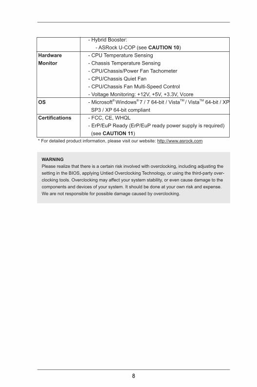
- Hybrid Booster: - ASRock U-COP (see CAUTION 10) Hardware - CPU Temperature Sensing Monitor - Chassis Temperature Sensing - CPU/Chassis/Power Fan Tachometer - CPU/Chassis Quiet Fan - CPU/Chassis Fan Multi-Speed Control - Voltage Monitoring: +12V, +5V, +3.3V, Vcore OS - Microsoft® Windows® 7 / 7 64-bit / VistaTM / VistaTM 64-bit / XP SP3 / XP 64-bit compliant Certifications - FCC, CE, WHQL - ErP/EuP Ready (ErP/EuP ready power supply is required) (see CAUTION 11) * For detailed product information, please visit our website: http://www.asrock.com
WARNINGPlease realize that there is a certain risk involved with overclocking, including adjusting the setting in the BIOS, applying Untied Overclocking Technology, or using the third-party over-clocking tools. Overclocking may affect your system stability, or even cause damage to the components and devices of your system. It should be done at your own risk and expense. We are not responsible for possible damage caused by overclocking.

9
CAUTION!1. This motherboard supports Dual Channel Memory Technology. Before
you implement Dual Channel Memory Technology, make sure to read the installation guide of memory modules on page 15 for proper installation.
2. Whether 2400/1866/1600MHz memory speed is supported depends on the CPU you adopt. If you want to adopt DDR3 2400/1866/1600 memory module on this motherboard, please refer to the memory support list on our website for the compatible memory modules.
ASRock website http://www.asrock.com3. Due to the operating system limitation, the actual memory size may be
less than 4GB for the reservation for system usage under Windows® 7 / VistaTM / XP. For Windows® 64-bit OS with 64-bit CPU, there is no such limitation.
4. The maximum shared memory size is defined by the chipset vendor and is subject to change. Please check AMD website for the latest informa-tion.
5. xvYCC and Deep Color are only supported under Windows® 7 64-bit / 7. Deep Color mode will be enabled only if the display supports 12bpc in EDID. HBR is supported under Windows® 7 64-bit / 7 / VistaTM 64-bit / VistaTM.
6. ASRock Extreme Tuning Utility (AXTU) is an all-in-one tool to ne-tune different system functions in a user-friendly interface, which is including Hardware Monitor, Fan Control and IES. In Hardware Monitor, it shows the major readings of your system. In Fan Control, it shows the fan speed and temperature for you to adjust. In IES (Intelligent Energy Saver), the voltage regulator can reduce the number of output phases to improve efficiency when the CPU cores are idle without sacrificing computing performance. Please visit our website for the operation procedures of ASRock Extreme Tuning Utility (AXTU).
ASRock website: http://www.asrock.com7. ASRock Instant Flash is a BIOS flash utility embedded in Flash ROM.
This convenient BIOS update tool allows you to update system BIOS without entering operating systems first like MS-DOS or Windows®. With this utility, you can press <F6> key during the POST or press <F2> key to BIOS setup menu to access ASRock Instant Flash. Just launch this tool and save the new BIOS file to your USB flash drive, floppy disk or hard drive, then you can update your BIOS only in a few clicks without prepar-ing an additional floppy diskette or other complicated flash utility. Please be noted that the USB flash drive or hard drive must use FAT32/16/12 file system.

10
8. If you desire a faster, less restricted way of charging your Apple devices, such as iPhone/iPod/iPad Touch, ASRock has prepared a wonderful solu-tion for you - ASRock APP Charger. Simply installing the APP Charger driver, it makes your iPhone charged much quickly from your computer and up to 40% faster than before. ASRock APP Charger allows you to quickly charge many Apple devices simultaneously and even supports continuous charging when your PC enters into Standby mode (S1), Sus-pend to RAM (S3), hibernation mode (S4) or power off (S5). With APP Charger driver installed, you can easily enjoy the marvelous charging experience than ever.
ASRock website: http://www.asrock.com/Feature/AppCharger/index.asp9. ASRock XFast USB can boost USB storage device performance. The
performance may depend on the property of the device.10. While CPU overheat is detected, the system will automatically shutdown.
Before you resume the system, please check if the CPU fan on the moth-erboard functions properly and unplug the power cord, then plug it back again. To improve heat dissipation, remember to spray thermal grease between the CPU and the heatsink when you install the PC system.
11. EuP, stands for Energy Using Product, was a provision regulated by Eu-ropean Union to define the power consumption for the completed system. According to EuP, the total AC power of the completed system shall be under 1.00W in off mode condition. To meet EuP standard, an EuP ready motherboard and an EuP ready power supply are required. According to Intel’s suggestion, the EuP ready power supply must meet the standard of 5v standby power efficiency is higher than 50% under 100 mA current consumption. For EuP ready power supply selection, we recommend you checking with the power supply manufacturer for more details.

11
1.3 Motherboard Layout
1 ATX 12V Power Connector (ATX12V1) 16 COM Port Header (COM1) 2 CPU Heatsink Retention Module 17 System Panel Header (PANEL1, White) 3 CPU Socket 18 Clear CMOS Jumper (CLRCMOS1) 4 CPU Fan Connector (CPU_FAN1) 19 Chassis Fan Connector (CHA_FAN1) 5 2 x 240-pin DDR3 DIMM Slots 20 Infrared Module Header (IR1) (Dual Channel: DDR3_A1, DDR3_B1; Blue) 21 USB 2.0 Header (USB6_7, Blue) 6 ATX Power Connector (ATXPWR1) 22 Consumer Infrared Module Header (CIR1) 7 SATA3 Connector (SATA_3, White) 23 USB 2.0 Header (USB8_9, Blue) 8 SATA3 Connector (SATA_5, White) 24 USB 2.0 Header (USB10_11, Blue) 9 SATA3 Connector (SATA_6, White) 25 Front Panel Audio Header (HD_AUDIO1, White)10 SATA3 Connector (SATA_4, White) 26 PCI Slot (PCI1)11 SATA3 Connector (SATA_2, White) 27 PCI Express 2.0 x16 Slot (PCIE2; Blue)12 SATA3 Connector (SATA_1, White) 28 PCI Express 2.0 x1 Slot (PCIE1; White) 13 Chassis Speaker Header (SPEAKER 1, White) 29 SPI Flash Memory (32Mb)14 Southbridge Controller 30 Power Fan Connector (PWR_FAN1) 15 Print Port Header (LPT1, White)
SuperI/O
CMOS
BATTERY
AT
XP
WR
1
AMDA75 FCH
(Hudson-D3)Chipset
COM1
PCIE1
PCI1
LAN
AUDIOCODEC
1
CLRCMOS1
1
CPU_FAN1
HDLED RESET
PLED PWRBTN
1
PANEL 1CHA_FAN1
SPEAKER11
HD_AUDIO1
1
22
.6c
m(8
.9-i
n)
21.6cm (8.5-in)
6
7
1 2 43 5
8
9
10
11
1213
14
1516171819202122232425
26
27
28
29
32MbBIOS
IR1
1
PCIE2
FS
B8
00
DD
R3
_A
1(6
4b
it,2
40
-pin
mo
du
le)
DD
R3
_B
1(6
4b
it,2
40
-pin
mo
du
le)
SA
TA_
2
HD
MI1
To
p:
LIN
EIN
Ce
nte
r:
FR
ON
T
Bo
ttom
:M
ICIN
RJ
-45
LA
N
11 1
USB6_7USB8_9USB10_11
PWR_FAN1
A75M-HVS
ErP/EuP Ready
Des
ign
edin
Taip
ei
RoHS
DD
R3
24
00
+D
X11
USB 2.0T: USB0B: USB1
CIR1
1
SOC
KET
FM1
SA
TA_
1
SA
TA_
4
SA
TA_
3
1
LPT1
ATX12V1
HD
MI1
.4a
PS
2
Mo
us
e
PS
2K
ey
bo
ard
VG
A1
USB 3.0T: USB2B: USB3
30
SA
TA_
6
SA
TA_
5
USB 3.0T: USB4B: USB5
Dual Graphics
XF
as
tU
SB
SATA3 6Gb/sUSB 3.0

12
1.4 I/O Panel
* There are two LED next to the LAN port. Please refer to the table below for the LAN port LED indications. LAN Port LED Indications
Activity/Link LED SPEED LEDStatus Description Status Description Off No Link Off 10Mbps connectionBlinking Data Activity Orange 100Mbps connectionOn Link Green 1Gbps connection
1 PS/2 Mouse Port (Green) 7 USB 3.0 Ports (USB45) * 2 LAN RJ-45 Port 8 USB 3.0 Ports (USB23) 3 Line In (Light Blue) 9 HDMI Port ** 4 Front Speaker (Lime) 10 D-Sub Port 5 Microphone (Pink) 11 PS/2 Keyboard Port (Purple) *** 6 USB 2.0 Ports (USB01)
LAN Port
ACT/LINK LED
SPEED LED
6791011
1 2
4
3
5
8
** To enable Multi-Streaming function, you need to connect a front panel audio cable to the front panel audio header. After restarting your computer, you will find “VIA HD Audio Deck” tool on your system. Please follow below instructions according to the OS you install. For Windows® XP / XP 64-bit OS: Please click “VIA HD Audio Deck” icon , and click “Speaker”. Then you are allowed to
select “2 Channel” or “4 Channel”. Click “Power” to save your change. For Windows® 7 / 7 64-bit / VistaTM / VistaTM 64-bit OS: Please click “VIA HD Audio Deck” icon , and click “Advanced Options” on the left side
on the bottom. In “Advanced Options” screen, select “Independent Headphone”, and click “OK” to save your change.
*** It is recommended to install the USB Keyboard/Mouse cable to USB 2.0 ports (USB01) instead of USB 3.0 ports.
13
2. Installation This is a Micro ATX form factor (8.9-in x 8.5-in, 22.6 cm x 21.6 cm) motherboard.Before you install the motherboard, study the configuration of your chassis to ensure that the motherboard fits into it.
Pre-installation PrecautionsTake note of the following precautions before you install motherboard components or change any motherboard settings.
Before you install or remove any component, ensure that the power is switched off or the power cord is detached from the power supply. Failure to do so may cause severe damage to the motherboard, peripherals, and/or components.
1. Unplug the power cord from the wall socket before touching any component.
2. To avoid damaging the motherboard components due to static elec-tricity, NEVER place your motherboard directly on the carpet or the like. Also remember to use a grounded wrist strap or touch a safety grounded object before you handle components.
3. Hold components by the edges and do not touch the ICs. 4. Whenever you uninstall any component, place it on a grounded anti-
static pad or in the bag that comes with the component.5. When placing screws into the screw holes to secure the mother-
board to the chassis, please do not over-tighten the screws! Doing so may damage the motherboard.
14
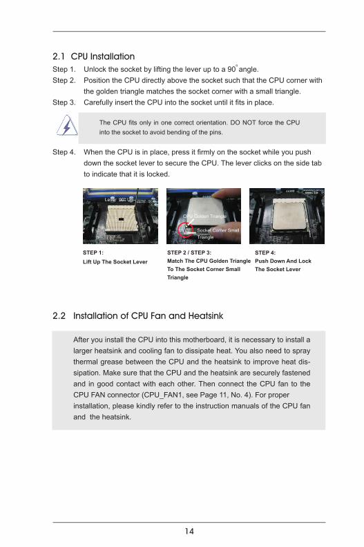
2.1 CPU Installation Step 1. Unlock the socket by lifting the lever up to a 90
o angle.Step 2. Position the CPU directly above the socket such that the CPU corner with the golden triangle matches the socket corner with a small triangle.Step 3. Carefully insert the CPU into the socket until it fits in place.
The CPU fits only in one correct orientation. DO NOT force the CPU into the socket to avoid bending of the pins.
Step 4. When the CPU is in place, press it firmly on the socket while you push down the socket lever to secure the CPU. The lever clicks on the side tab to indicate that it is locked.
2.2 Installation of CPU Fan and Heatsink
After you install the CPU into this motherboard, it is necessary to install a larger heatsink and cooling fan to dissipate heat. You also need to spray thermal grease between the CPU and the heatsink to improve heat dis-sipation. Make sure that the CPU and the heatsink are securely fastened and in good contact with each other. Then connect the CPU fan to the CPU FAN connector (CPU_FAN1, see Page 11, No. 4). For proper installation, please kindly refer to the instruction manuals of the CPU fan and the heatsink.
STEP 1:Lift Up The Socket Lever
STEP 2 / STEP 3: Match The CPU Golden TriangleTo The Socket Corner Small Triangle
STEP 4:Push Down And LockThe Socket Lever
CPU Golden Triangle
Lever 90° Up
Socket Corner Small Triangle

15
2.3 Installation of Memory Modules (DIMM)This motherboard provides two 240-pin DDR3 (Double Data Rate 3) DIMM slots, and supports Dual Channel Memory Technology. For dual channel configuration, you always need to install two identical (the same brand, speed, size and chip-type) memory modules in the DDR3 DIMM slots to activate Dual Channel Memory Technology. Otherwise, it will operate at single channel mode.
1. It is not allowed to install a DDR or DDR2 memory module into DDR3 slot;otherwise, this motherboard and DIMM may be damaged. 2. If you install only one memory module or two non-identical memory modules, it is unable to activate the Dual Channel Memory Technology.
Installing a DIMM
Please make sure to disconnect power supply before adding or removing DIMMs or the system components.
Step 1. Unlock a DIMM slot by pressing the retaining clips outward. Step 2. Align a DIMM on the slot such that the notch on the DIMM matches the break on the slot.
The DIMM only fits in one correct orientation. It will cause permanent damage to the motherboard and the DIMM if you force the DIMM into the slot at incorrect orientation.
Step 3. Firmly insert the DIMM into the slot until the retaining clips at both ends fully snap back in place and the DIMM is properly seated.

16
2.4 Expansion Slots (PCI and PCI Express Slots)There are 1 PCI slot and 2 PCI Express slots on this motherboard. PCI Slot: PCI slot is used to install expansion cards that have the 32-bit PCI interface. PCIE Slots: PCIE1 (PCIE x1 slot; White) is used for PCI Express cards with x1 lane
width cards, such as Gigabit LAN card and SATA2 card. PCIE2 (PCIE x16 slot; Blue) is used for PCI Express x16 lane width
graphics cards.
Installing an expansion card
Step 1. Before installing the expansion card, please make sure that the power supply is switched off or the power cord is unplugged. Please read the documentation of the expansion card and make necessary hardware
settings for the card before you start the installation.Step 2. Remove the system unit cover (if your motherboard is already installed
in a chassis).Step 3. Remove the bracket facing the slot that you intend to use. Keep the
screws for later use. Step 4. Align the card connector with the slot and press firmly until the card is
completely seated on the slot. Step 5. Fasten the card to the chassis with screws. Step 6. Replace the system cover.
17
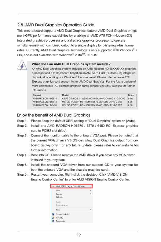
2.5 AMD Dual Graphics Operation GuideThis motherboard supports AMD Dual Graphics feature. AMD Dual Graphics brings multi-GPU performance capabilities by enabling an AMD A75 FCH (Hudson-D3) integrated graphics processor and a discrete graphics processor to operate simultaneously with combined output to a single display for blisteringly-fast frame rates. Currently, AMD Dual Graphics Technology is only supported with Windows® 7 OS, and is not available with Windows® VistaTM / XP OS.
What does an AMD Dual Graphics system include? An AMD Dual Graphics system includes an AMD Radeon HD 65XX/64XX graphics processor and a motherboard based on an AMD A75 FCH (Hudson-D3) integrated chipset, all operating in a Windows® 7 environment. Please refer to below PCI Express graphics card support list for AMD Dual Graphics. For the future update of more compatible PCI Express graphics cards, please visit AMD website for further information.
Chipset Model DriverAMD RADEON HD6670 ASUS DIS-PCIE2.1-ASUS-HDMI-EAH6670-DI-1GD3/1G-DDR3 8.86AMD RADEON HD6570 MSI DIS-PCIE2.1-MSI-HDMI-R6570-MD1GD3-LP/1G-DDR3 8.86AMD RADEON HD6450 MSI DIS-PCIE2.1-MSI-HDMI-R6450-MD1GD3-LP/1G-DDR3 8.86
Enjoy the benefit of AMD Dual Graphics Step 1. Please keep the default UEFI setting of “Dual Graphics“ option on [Auto]. Step 2. Install one AMD RADEON HD6670 / 6570 / 6450 PCI Express graphics
card to PCIE2 slot (blue). Step 3. Connect the monitor cable to the onboard VGA port. Please be noted that
the current VGA driver / VBIOS can allow Dual Graphics output from on-board display only. For any future update, please refer to our website for further information.
Step 4. Boot into OS. Please remove the AMD driver if you have any VGA driver installed in your system. Step 5. Install the onboard VGA driver from our support CD to your system for
both the onboard VGA and the discrete graphics card.Step 6. Restart your computer. Right-click the desktop. Click “AMD VISION Engine Control Center” to enter AMD VISION Engine Control Center.

18
* Dual Graphics appearing here is a registered trademark of AMD Technologies Inc., and is used only for identification or explanation and to the owners’ benefit, without intent to infringe.* For further information of AMD Dual Graphics technology, please check AMD website for up dates and details.
Step 9. Click “Enable CrossFireTM” and click “Apply“ to save your change.
Step 10. Reboot your system. Then you can freely enjoy the benefit of Dual Graphics feature.
AMD VISION Engine Control Center
Step 7. You can also click “AMD VISION Engine Control Center” on your Windows® taskbar to enter AMD VISION Engine Control Center.
Step 8. In AMD VISION Engine Control Center, please choose “Performance”. Click “AMD CrossFireTM”.
19
2. If you have installed onboard VGA driver from our support CD to your system already, you can freely enjoy the benefits of dual monitor function after your system boots. If you haven’t installed onboard VGA driver yet, please install onboard VGA driver from our support CD to your system and restart your computer.
2.6 Dual Monitor and Surround Display Features
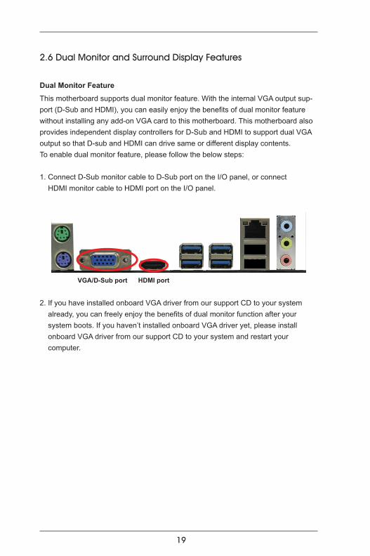
Dual Monitor Feature
This motherboard supports dual monitor feature. With the internal VGA output sup-port (D-Sub and HDMI), you can easily enjoy the benefits of dual monitor feature without installing any add-on VGA card to this motherboard. This motherboard also provides independent display controllers for D-Sub and HDMI to support dual VGA output so that D-sub and HDMI can drive same or different display contents.To enable dual monitor feature, please follow the below steps:
1. Connect D-Sub monitor cable to D-Sub port on the I/O panel, or connect HDMI monitor cable to HDMI port on the I/O panel.
HDMI portVGA/D-Sub port

20
Surround Display FeatureThis motherboard supports surround display upgrade. With the internal VGA output support (D-Sub and HDMI) and external add-on PCI Express VGA cards, you can easily enjoy the benefits of surround display feature. Please refer to the following steps to set up a surround display environment:
1. Install the PCI Express VGA cards on PCIE2 slot. Please refer to page 16 for proper expansion card installation procedures for details.2. Connect D-Sub monitor cable to D-Sub port on the I/O panel, or connect HDMI monitor cable to HDMI port on the I/O panel. Then connect other monitor cables to the corresponding connectors of the add-on PCI Express VGA cards on PCIE2 slot.3. Boot your system. Press <F2> or <Del> to enter UEFI setup. Enter “Share Memory” option to adjust the memory capability to [32MB], [64MB], [128MB], [256MB] or [512MB] to enable the function of D-sub. Please make sure that the value you select is less than the total capability of the system memory. If you do not adjust the UEFI setup, the default value of “Share Memory”, [Auto], will disable D-Sub function when the add-on VGA card is inserted to this motherboard.4. Install the onboard VGA driver and the add-on PCI Express VGA card driver to your system. If you have installed the drivers already, there is no need to install them again. 5. Set up a multi-monitor display.
For Windows® XP / XP 64-bit OS: Right click the desktop, choose “Properties”, and select the “Settings” tab so that you can adjust the parameters of the multi-monitor according to the steps below. A. Click the “Identify” button to display a large number on each monitor. B. Right-click the display icon in the Display Properties dialog that you wish to be your primary monitor, and then select “Primary”. When you use multiple monitors with your card, one monitor will always be Primary, and all additional monitors will be designated as Secondary. C. Select the display icon identified by the number 2. D. Click “Extend my Windows desktop onto this monitor”. E. Right-click the display icon and select “Attached”, if necessary. F. Set the “Screen Resolution” and “Color Quality” as appropriate for the second monitor. Click “Apply” or “OK” to apply these new values. G. Repeat steps C through E for the diaplay icon identified by the number one to four.

21
For Windows® 7 / 7 64-bit / VistaTM / VistaTM 64-bit OS: Right click the desktop, choose “Personalize”, and select the “Display Settings” tab so that you can adjust the parameters of the multi-monitor according to the steps below. A. Click the number ”2” icon. B. Click the items “This is my main monitor” and “Extend the desktop onto this monitor”. C. Click “OK” to save your change. D. Repeat steps A through C for the display icon identified by the number three to four.6. Use Surround Display. Click and drag the display icons to positions representing the physical setup of your monitors that you would like to use. The placement of display icons determines how you move items from one monitor to another.
HDCP Function HDCP function is supported on this motherboard. To use HDCP function with this motherboard, you need to adopt the monitor that supports HDCP function as well. Therefore, you can enjoy the superior display quality with high-definition HDCP encryption contents. Please refer to below instruction for more details about HDCP function.
What is HDCP? HDCP stands for High-Bandwidth Digital Content Protection, a specification developed by Intel® for protecting digital entertainment content that uses the DVI interface. HDCP is a copy protection scheme to eliminate the possibility of intercepting digital data midstream between the video source, or transmitter - such as a computer, DVD player or set-top box - and the digital display, or receiver - such as a monitor, television or projector. In other words, HDCP specification is designed to protect the integrity of content as it is being transmitted.
Products compatible with the HDCP scheme such as DVD players, satellite and cable HDTV set-top-boxes, as well as few entertainment PCs requires a secure connection to a compliant display. Due to the increase in manufacturers employing HDCP in their equipment, it is highly recommended that the HDTV or LCD monitor you purchase is compatible.

22
* ASRock Smart Remote is only supported by some of ASRock motherboards. Please refer to ASRock website for the motherboard support list: http://www.asrock.com
USB 2.0 header (9-pin, blue)
CIR header (4-pin, white)
2.7 ASRock Smart Remote Installation GuideASRock Smart Remote is only used for ASRock motherboard with CIR header. Please refer to below procedures for the quick installation and usage of ASRock Smart Remote.
Step1. Find the CIR header located next to the USB 2.0 header on ASRock motherboard.
Step2. Connect the front USB cable to the USB 2.0 header (as below, pin 1-5) and the CIR header. Please make sure the wire assignments and the pin assignments are matched correctly.
USB_PWR
P-P+
GND
ATX+5VSBIRRX
IRTXGND
DUMMY
Step3. Install Multi-Angle CIR Receiver to the front USB port. If Multi-Angle CIR Receiver cannot successfully receive the infrared signals from MCE Remote Controller, please try to install it to the other front USB port.
3 CIR sensors in different angles
1. Only one of the front USB port can support CIR function. When the CIR function is enabled, the other port will remain USB function.
2. Multi-Angle CIR Receiver is used for front USB only. Please do not use the rear USB bracket to connect it on the rear panel. Multi-Angle CIR Receiver can receive the multi-direction infrared signals (top, down and front), which is compatible with most of the chassis on the market.
3. The Multi-Angle CIR Receiver does not support Hot-Plug function. Please install it before you boot the system.
23
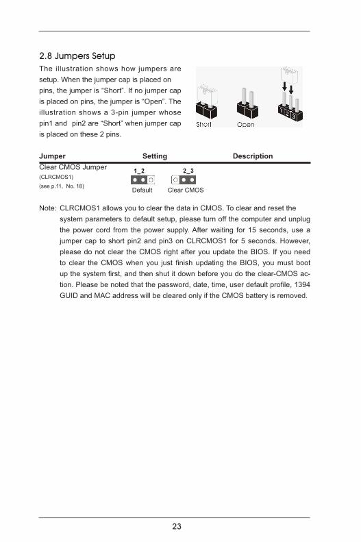
2.8 Jumpers Setup The illustration shows how jumpers are setup. When the jumper cap is placed on pins, the jumper is “Short”. If no jumper cap is placed on pins, the jumper is “Open”. The illustration shows a 3-pin jumper whose pin1 and pin2 are “Short” when jumper cap is placed on these 2 pins.
Jumper Setting DescriptionClear CMOS Jumper (CLRCMOS1)
(see p.11, No. 18)
Note: CLRCMOS1 allows you to clear the data in CMOS. To clear and reset the system parameters to default setup, please turn off the computer and unplug
the power cord from the power supply. After waiting for 15 seconds, use a jumper cap to short pin2 and pin3 on CLRCMOS1 for 5 seconds. However, please do not clear the CMOS right after you update the BIOS. If you need to clear the CMOS when you just finish updating the BIOS, you must boot up the system first, and then shut it down before you do the clear-CMOS ac-tion. Please be noted that the password, date, time, user default profile, 1394 GUID and MAC address will be cleared only if the CMOS battery is removed.
Clear CMOSDefault
24
2.9 Onboard Headers and Connectors
Onboard headers and connectors are NOT jumpers. Do NOT place jumper caps over these headers and connectors. Placing jumper caps over the headers and connectors will cause permanent damage of the motherboard!
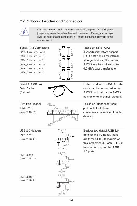
Serial ATA3 Connectors These six Serial ATA3 (SATA_1: see p.11, No. 12) (SATA3) connectors support (SATA_2: see p.11, No. 11) SATA data cables for internal (SATA_3: see p.11, No. 7) storage devices. The current (SATA_4: see p.11, No. 10) SATA3 interface allows up to(SATA_5: see p.11, No. 8) 6.0 Gb/s data transfer rate.(SATA_6: see p.11, No. 9)
Serial ATA (SATA) Either end of the SATA data Data Cable cable can be connected to the (Optional) SATA3 hard disk or the SATA3 connector on this motherboard.
1
USB_PWRP-8
GND
DUMMY
USB_PWR
P+8
GND
P-9P+9
1
USB_PWRP-10
GND
DUMMY
USB_PWR
P+10
GND
P-11P+11
USB 2.0 Headers Besides two default USB 2.0(9-pin USB6_7) ports on the I/O panel, there (see p.11 No. 21) are three USB 2.0 headers on this motherboard. Each USB 2.0 header can support two USB 2.0 ports.(9-pin USB8_9)(see p.11 No. 23)
(9-pin USB10_11)(see p.11 No. 24)
Print Port Header This is an interface for print (25-pin LPT1) port cable that allows (see p.11 No. 15) convenient connection of printer devices.
1
AFD#ERROR#
PINIT#GNDSLIN#
STB#SPD0
SPD1SPD2
SPD3SPD4
SPD5SPD6
SPD7ACK#
BUSYPE
SLCT
SATA
_2
SA
TA_4
SAT
A_6
SATA
_1
S
ATA_
3
SA
TA_5
25
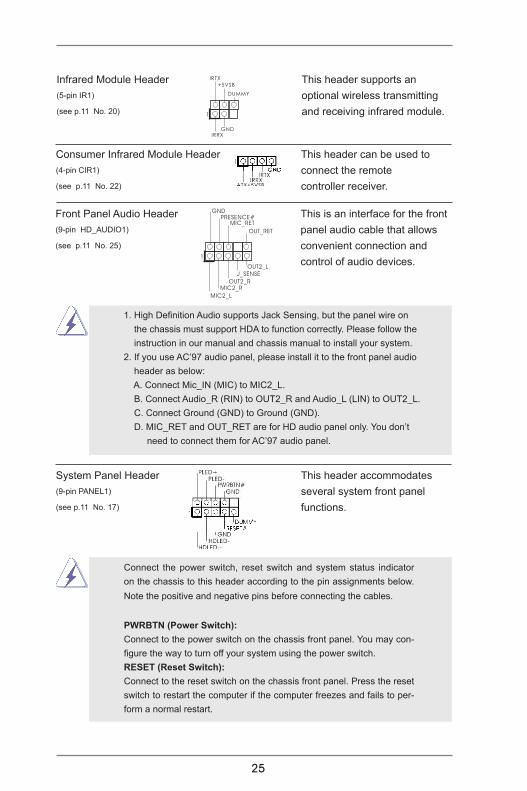
Infrared Module Header This header supports an(5-pin IR1) optional wireless transmitting(see p.11 No. 20) and receiving infrared module.
Front Panel Audio Header This is an interface for the front (9-pin HD_AUDIO1) panel audio cable that allows (see p.11 No. 25) convenient connection and control of audio devices.
Consumer Infrared Module Header This header can be used to (4-pin CIR1) connect the remote (see p.11 No. 22) controller receiver.
1
IRTX
+5VSB
DUMMY
IRRXGND
J_SENSE
OUT2_L
1
MIC_RETPRESENCE#
GND
OUT2_RMIC2_R
MIC2_L
OUT_RET
1. High Definition Audio supports Jack Sensing, but the panel wire on the chassis must support HDA to function correctly. Please follow the instruction in our manual and chassis manual to install your system.
2. If you use AC’97 audio panel, please install it to the front panel audio header as below:
A. Connect Mic_IN (MIC) to MIC2_L. B. Connect Audio_R (RIN) to OUT2_R and Audio_L (LIN) to OUT2_L. C. Connect Ground (GND) to Ground (GND). D. MIC_RET and OUT_RET are for HD audio panel only. You don’t
need to connect them for AC’97 audio panel.
System Panel Header This header accommodates(9-pin PANEL1) several system front panel (see p.11 No. 17) functions.
Connect the power switch, reset switch and system status indicator on the chassis to this header according to the pin assignments below. Note the positive and negative pins before connecting the cables.
PWRBTN (Power Switch): Connect to the power switch on the chassis front panel. You may con-figure the way to turn off your system using the power switch.
RESET (Reset Switch): Connect to the reset switch on the chassis front panel. Press the reset switch to restart the computer if the computer freezes and fails to per-form a normal restart.

26
PLED (System Power LED): Connect to the power status indicator on the chassis front panel. The LED is on when the system is operating. The LED keeps blinking when the sys-tem is in S1 sleep state. The LED is off when the system is in S3/S4 sleep state or powered off (S5).
HDLED (Hard Drive Activity LED): Connect to the hard drive activity LED on the chassis front panel. The LED is on when the hard drive is reading or writing data.
The front panel design may differ by chassis. A front panel module mainly consists of power switch, reset switch, power LED, hard drive activity LED, speaker and etc. When connecting your chassis front panel module to this header, make sure the wire assignments and the pin assign-ments are matched correctly.
Chassis Speaker Header Please connect the chassis (4-pin SPEAKER 1) speaker to this header.(see p.11 No. 13)
Chassis and Power Fan Connectors Please connect the fan cables (4-pin CHA_FAN1) to the fan connectors and (see p.11 No. 19) match the black wire to the ground pin. (3-pin PWR_FAN1)(see p.11 No. 30)
GND+12V
CHA_FAN_SPEED
FAN_SPEED_CONTROL
CPU Fan Connectors Please connect the CPU fan (4-pin CPU_FAN1) cable to the connector and (see p.11 No. 4) match the black wire to the ground pin.
Though this motherboard provides 4-Pin CPU fan (Quiet Fan) support, the 3-Pin CPU fan still can work successfully even without the fan speed control function. If you plan to connect the 3-Pin CPU fan to the CPU fan connector on this motherboard, please connect it to Pin 1-3.
Pin 1-3 Connected
3-Pin Fan Installation
GND+12V
CPU_FAN_SPEED
FAN_SPEED_CONTROL
1 2 3 4
ATX Power Connector Please connect an ATX power (24-pin ATXPWR1) supply to this connector. (see p.11 No. 6)
12
1
24
13

27
Though this motherboard provides 24-pin ATX power connector, it can still work if you adopt a traditional 20-pin ATX power supply. To use the 20-pin ATX power supply, please plug your power supply along with Pin 1 and Pin 13.
ATX 12V Power Connector Please connect an ATX 12V (8-pin ATX12V1) power supply to this connector.(see p.11 No. 1)
Though this motherboard provides 8-pin ATX 12V power connector, it can still work if you adopt a traditional 4-pin ATX 12V power supply. To use the 4-pin ATX power supply, please plug your power supply along with Pin 1 and Pin 5.
20-Pin ATX Power Supply Installation
4-Pin ATX 12V Power Supply Installation
12
1
24
13
5 1
8 4
5 1
8 4
Serial port Header This COM1 header supports a (9-pin COM1) serial port module. (see p.11 No.16)
28
2.10 Serial ATA3 (SATA3) Hard Disks Installation This motherboard adopts AMD A75 FCH (Hudson-D3) chipset that supports Serial ATA3 (SATA3) hard disks and RAID (RAID 0, RAID 1 and RAID 10) functions. You may install SATA3 hard disks on this motherboard for internal storage devices. This section will guide you to install the SATA3 hard disks.
STEP 1: Install the SATA3 hard disks into the drive bays of your chassis. STEP 2: Connect the SATA power cable to the SATA3 hard disk.STEP 3: Connect one end of the SATA data cable to the motherboard’s SATA3 con-
nector.STEP 4: Connect the other end of the SATA data cable to the SATA3 hard disk.
2.11 Hot Plug and Hot Swap Functions for SATA3 HDDs This motherboard supports Hot Plug and Hot Swap functions for SATA3 in RAID / AHCI mode. AMD A75 FCH (Hudson-D3) chipset provides hardware support for Advanced Host controller Interface (AHCI), a new programming interface for SATA host controllers developed thru a joint industry effort.
NOTE What is Hot Plug Function?If the SATA3 HDDs are NOT set for RAID configuration, it is called “Hot Plug” for the action to insert and remove the SATA3 HDDs while the system is still power-on and in working condition. However, please note that it cannot perform Hot Plug if the OS has been installed into the SATA3 HDD.
What is Hot Swap Function?If SATA3 HDDs are built as RAID 1 then it is called “Hot Swap” for the ac-tion to insert and remove the SATA3 HDDs while the system is still power-on and in working condition.

29
Caution1. Without SATA 15-pin power connector interface, the SATA3 Hot Plug cannot be processed.2. Even some SATA3 HDDs provide both SATA 15-pin power connector and IDE 1x4-pin conventional power connector interfaces, the IDE 1x4-pin conventional power connector interface is definitely not able to support Hot Plug and will cause the HDD damage and data loss.
SATA 7-pinconnector
A. SATA data cable (Red) B. SATA power cable
2.12 SATA3 HDD Hot Plug Feature and Operation GuideThis motherboard supports Hot Plug feature for SATA3 HDD in RAID / AHCI mode. Please read below operation guide of Hot Plug feature carefully. Before you process the SATA3 HDD Hot Plug, please check below cable accessories from the motherboard gift box pack.A. 7-pin SATA data cableB. SATA power cable with SATA 15-pin power connector interface
The SATA 15-pin power connector (Black) connect to SATA3 HDD
Points of attention, before you process the Hot Plug: 1. Below operation procedure is designed only for our motherboard, which supports SATA3 HDD Hot Plug. * The SATA3 Hot Plug feature might not be supported by the chipset because of its limitation, the SATA3 Hot Plug support information of our motherboard is indicated in the product spec on our website: www.asrock.com2. Make sure your SATA3 HDD can support Hot Plug function from your dealer or HDD user manual. The SATA3 HDD, which cannot support Hot Plug function, will be damaged under the Hot Plug operation.3. Please make sure the SATA3 driver is installed into system properly. The latest SATA3 driver is available on our support website: www.asrock.com4. Make sure to use the SATA power cable & data cable, which are from our motherboard package.5. Please follow below instructions step by step to reduce the risk of HDD crash or data loss.
1x4-pin conventionalpower connector (White)connect to power supply

30
How to Hot Plug a SATA3 HDD:Points of attention, before you process the Hot Plug:Please do follow below instruction sequence to process the Hot Plug, improper procedure will cause the SATA3 HDD damage and data loss.
Connect SATA 15-pin power cable connector (Black) end to SATA3 HDD.
How to Hot Unplug a SATA3 HDD:
Points of attention, before you process the Hot Unplug:Please do follow below instruction sequence to process the Hot Unplug, improper procedure will cause the SATA3 HDD damage and data loss.
Please connect SATA power cable 1x4-pinend (White) to the power supply 1x4-pin cable.
Step 1 Step 2
Step 4
Step 2
SATA power cable 1x4-pinpower connector (White)
Unplug SATA data cable from SATA3 HDD side.
Unplug SATA 15-pin power cable connector (Black) from SATA3 HDD side.
Step 1
Connect SATA data cable to the SATA3 HDD.
Step 3
Connect SATA data cable to the motherboard’s SATAII / SATA3 connector.

31
2.13 Driver Installation GuideTo install the drivers to your system, please insert the support CD to your optical drive first. Then, the drivers compatible to your system can be auto-detected and listed on the support CD driver page. Please follow the order from up to bottom side to install those required drivers. Therefore, the drivers you install can work properly.
2.14 Installing Windows® 7 / 7 64-bit / VistaTM / VistaTM 64-bit / XP /
XP 64-bit With RAID FunctionsIf you want to install Windows® 7 / 7 64-bit / VistaTM / VistaTM 64-bit / XP / XP 64-bit on a RAID disk composed of 2 or more SATA3 HDDs with RAID functions, please follow below procedures according to the OS you install.
2.14.1 Installing Windows® XP / XP 64-bit With RAID FunctionsIf you want to install Windows® XP / XP 64-bit on a RAID disk composed of 2 or more SATA3 HDDs with RAID functions, please follow below steps.
STEP 1: Set up UEFI.A. Enter UEFI SETUP UTILITY Advanced screen Storage Configuration.B. Set the “SATA Mode” option to [RAID]. STEP 2: Make a SATA3 Driver Diskette. (Please use USB floppy or floppy disk.) A. Insert the ASRock Support CD into your optical drive to boot your system. B. During POST at the beginning of system boot-up, press <F11> key, and then a window for boot devices selection appears. Please select CD-ROM
as the boot device.C. When you see the message on the screen, “Generate Serial ATA driver
diskette [YN]?”, press <Y>.D. Then you will see these messages, Please insert a diskette into the floppy drive. WARNING! Formatting the floppy diskette will lose ALL data in it! Start to format and copy files [YN]? Please insert a floppy diskette into the floppy drive, and press any key.E. The system will start to format the floppy diskette and copy SATA3 drivers
into the floppy diskette.

32
2.14.2 Installing Windows® 7 / 7 64-bit / VistaTM / VistaTM 64-bit With
RAID FunctionsIf you want to install Windows® 7 / 7 64-bit / VistaTM / VistaTM 64-bit on a RAID disk composed of 2 or more SATA3 HDDs with RAID functions, please follow below steps.
STEP 1: Set up UEFI.A. Enter UEFI SETUP UTILITY Advanced screen Storage Configuration.B. Set the “SATA Mode” option to [RAID]. STEP 2: Use “RAID Installation Guide” to set RAID configuration. Before you start to configure RAID function, you need to check the RAID installation guide in the Support CD for proper configuration. Please refer to the BIOS RAID installation guide part of the document in the following path in the Support CD: .. \ RAID Installation GuideSTEP 3: Make a SATA3 Driver Diskette.Make a SATA3 driver diskette by following section 2.14.1 step 2 on page 31.STEP 4: Install Windows® 7 / 7 64-bit / VistaTM / VistaTM 64-bit OS on your system.
STEP 3: Use “RAID Installation Guide” to set RAID configuration. Before you start to configure RAID function, you need to check the RAID installation guide in the Support CD for proper configuration. Please refer to the BIOS RAID installation guide part of the document in the following path in the Support CD: .. \ RAID Installation GuideSTEP 4: Install Windows® XP / XP 64-bit OS on your system. After step 1, 2, 3, you can start to install Windows® XP / XP 64-bit OS on your system. At the beginning of Windows® setup, press F6 to install a third-party RAID driver. When prompted, insert the SATA3 driver diskette containing the AMD RAID driver. After reading the floppy disk, the driver will be presented. Select the driver to install according to the OS you install.
33
Using SATA3 HDDs without NCQ and Hot Plug functions (IDE mode)
STEP 1: Set up UEFI.A. Enter UEFI SETUP UTILITY Advanced screen Storage Configuration.B. Set the “SATA Mode” option to [IDE]. STEP 2: Install Windows® XP / XP 64-bit OS on your system.
2.15 Installing Windows® 7 / 7 64-bit / VistaTM / VistaTM 64-bit / XP /
XP 64-bit Without RAID FunctionsIf you want to install Windows® 7 / 7 64-bit / VistaTM / VistaTM 64-bit / XP / XP 64-bit OS on your SATA3 HDDs without RAID functions, please follow below procedures according to the OS you install.
2.15.1 Installing Windows® XP / XP 64-bit Without RAID FunctionsIf you want to install Windows® XP / XP 64-bit on your SATA3 HDDs without RAID functions, please follow below steps.
Using SATA3 HDDs with NCQ and Hot Plug functions (AHCI mode)
STEP 1: Set up UEFI.A. Enter UEFI SETUP UTILITY Advanced screen Storage Configuration.B. Set the “SATA Mode” option to [AHCI]. STEP 2: Make a SATA3 Driver Diskette.Make a SATA3 driver diskette by following section 2.14.1 step 2 on page 31.STEP 3: Install Windows® XP / XP 64-bit OS on your system.You can start to install Windows® XP / XP 64-bit OS on your system. At the begin-ning of Windows® setup, press F6 to install a third-party AHCI driver. When prompt-ed, insert the SATA3 driver diskette containing the AMD AHCI driver. After reading the floppy disk, the driver will be presented. Select the driver to install according to the OS you install.

34
STEP 1: Set up UEFI.A. Enter UEFI SETUP UTILITY Advanced screen Storage Configuration.B. Set the “SATA Mode” option to [IDE]. STEP 2: Install Windows® 7 / 7 64-bit / VistaTM / VistaTM 64-bit OS on your system.
Using SATA3 HDDs without NCQ and Hot Plug functions (IDE mode)
2.15.2 Installing Windows® 7 / 7 64-bit / VistaTM / VistaTM 64-bit
Without RAID FunctionsIf you want to install Windows® 7 / 7 64-bit / VistaTM / VistaTM 64-bit on your SATA3 HDDs without RAID functions, please follow below steps.
Using SATA3 HDDs with NCQ and Hot Plug functions (AHCI mode)
STEP 1: Set up UEFI.A. Enter UEFI SETUP UTILITY Advanced screen Storage Configuration.B. Set the “SATA Mode” option to [AHCI]. STEP 2: Install Windows® 7 / 7 64-bit / VistaTM / VistaTM 64-bit OS on your system.

35
3. UEFI SETUP UTILITY3.1 IntroductionThis section explains how to use the UEFI SETUP UTILITY to configure your sys-tem. The SPI Memory on the motherboard stores the UEFI SETUP UTILITY. You may run the UEFI SETUP UTILITY when you start up the computer. Please press <F2> or <Del> during the Power-On-Self-Test (POST) to enter the UEFI SETUP UTILITY, otherwise, POST will continue with its test routines.If you wish to enter the UEFI SETUP UTILITY after POST, restart the system by pressing <Ctl> + <Alt> + <Delete>, or by pressing the reset button on the system chassis. You may also restart by turning the system off and then back on.
Because the UEFI software is constantly being updated, the following UEFI setup screens and descriptions are for reference purpose only, and they may not exactly match what you see on your screen.
3.1.1 UEFI Menu Bar The top of the screen has a menu bar with the following selections: Main To set up the system time/date informationOC Tweaker To set up overclocking featuresAdvanced To set up the advanced UEFI featuresH/W Monitor To display current hardware statusBoot To set up the default system device to locate and load the
Operating SystemSecurity To set up the security featuresExit To exit the current screen or the UEFI SETUP UTILITY Use < > key or < > key to choose among the selections on the menu bar, and then press <Enter> to get into the sub screen.

36
3.1.2 Navigation Keys Please check the following table for the function description of each navigation key. Navigation Key(s) Function Description / Moves cursor left or right to select Screens / Moves cursor up or down to select items + / - To change option for the selected items<Enter> To bring up the selected screen<F1> To display the General Help Screen <F9> To load optimal default values for all the settings<F10> To save changes and exit the UEFI SETUP UTILITY<ESC> To jump to the Exit Screen or exit the current screen
3.2 Main ScreenWhen you enter the UEFI SETUP UTILITY, the Main screen will appear and display the system overview.
System Time [Hour:Minute:Second] Use this item to specify the system time. System Date [Day Month/Date/Year] Use this item to specify the system date.

37
3.3 OC Tweaker ScreenIn the OC Tweaker screen, you can set up overclocking features.
CPU ConfigurationSpread Spectrum
This item should always be [Auto] for better system stability. AMD Turbo Core Technology This item appears only when the processor you adopt supports this fea-
ture. Use this to select enable or disable AMD Turbo Core Technology. Configuration options: [Auto] and [Disabled]. The default value is [Auto].
Processor Maximum Frequency It will display Processor Maximum Frequency for reference.Processor Maximum Voltage It will display Processor Maximum Voltage for reference.Multiplier/Voltage Change This item is set to [Auto] by default. If it is set to [Manual], you may adjust
the value of Processor Frequency and Processor Voltage. However, it is recommended to keep the default value for system stability. CPU Frequency Multiplier For safety and system stability, it is not recommended to adjust the value
of this item. CPU Voltage It allows you to adjust the value of CPU voltage. However, for safety and
system stability, it is not recommended to adjust the value of this item.
DRAM Configuration DRAM Frequency
If [Auto] is selected, the motherboard will detect the memory module(s)inserted and assigns appropriate frequency automatically.

38
DRAM Timing Control
Power Down EnableUse this item to enable or disable DDR power down mode.
Bank InterleavingInterleaving allows memory accesses to be spread out over banks on the same node, or accross nodes, decreasing access contention.
Channel InterleavingIt allows you to enable Channel Memory Interleaving. Configuration op-tions: [Disabled], [Auto]. The default value is [Auto].
CAS# Latency (tCL) Use this item to change CAS# Latency (tCL) Auto/Manual setting. The default is [Auto]. RAS# to CAS# Delay (tRCD) Use this item to change RAS# to CAS# Delay (tRCD) Auto/Manual setting. The default is [Auto]. Row Precharge Time (tRP) Use this item to change Row Precharge Time (tRP) Auto/Manual setting. The default is [Auto]. RAS# Active Time (tRAS) Use this item to change RAS# Active Time (tRAS) Auto/Manual setting. The default is [Auto]. Command Rate (CR) Use this item to change Command Rate (CR) Auto/Manual setting. Min: 1T. Max: 2T. The default is [Auto]. RAS# Cycle Time (tRC) Use this item to change RAS# Cycle Time (tRC) Auto/Manual setting. The default is [Auto]. Write Recovery Time (tWR) Use this item to change Write Recovery Time (tWR) Auto/Manual setting. The default is [Auto].

39
Refresh Cyle Time (tRFC) Use this item to change Refresh Cyle Time (tRFC) Auto/Manual setting. The default is [Auto]. RAS to RAS Delay (tRRD) Use this item to change RAS to RAS Delay (tRRD) Auto/Manual setting. The default is [Auto]. Write to Read Delay (tWTR) Use this item to change Write to Read Delay (tWTR) Auto/Manual setting. The default is [Auto]. Read to Precharge (tRTP) Use this item to change Read to Precharge (tRTP) Auto/Manual setting. The default is [Auto]. Four Activate Window (tFAW) Use this item to change Four Activate Window (tFAW) Auto/Manual setting. The default is [Auto]. Voltage Control DRAM Voltage Use this to select DRAM Voltage. The default value is [Auto]. APU PCIE Voltage VDDP Use this to select APU PCIE Voltage VDDP. The default value is [Auto]. CPU Load-Line Calibration CPU Load-Line Calibration helps prevent CPU voltage droop when the system is under heavy load. SB Voltage Use this to select SB Voltage. The default value is [Auto].
Would you like to save current setting user defaults? In this option, you are allowed to load and save three user defaults according to your own requirements.
40
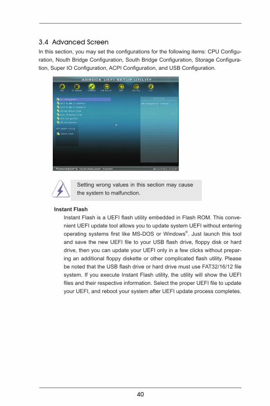
Instant FlashInstant Flash is a UEFI flash utility embedded in Flash ROM. This conve-nient UEFI update tool allows you to update system UEFI without entering operating systems first like MS-DOS or Windows®. Just launch this tool and save the new UEFI file to your USB flash drive, floppy disk or hard drive, then you can update your UEFI only in a few clicks without prepar-ing an additional floppy diskette or other complicated flash utility. Please be noted that the USB flash drive or hard drive must use FAT32/16/12 file system. If you execute Instant Flash utility, the utility will show the UEFI files and their respective information. Select the proper UEFI file to update your UEFI, and reboot your system after UEFI update process completes.
3.4 Advanced ScreenIn this section, you may set the configurations for the following items: CPU Configu-ration, Nouth Bridge Configuration, South Bridge Configuration, Storage Configura-tion, Super IO Configuration, ACPI Configuration, and USB Configuration.
Setting wrong values in this section may cause the system to malfunction.
41
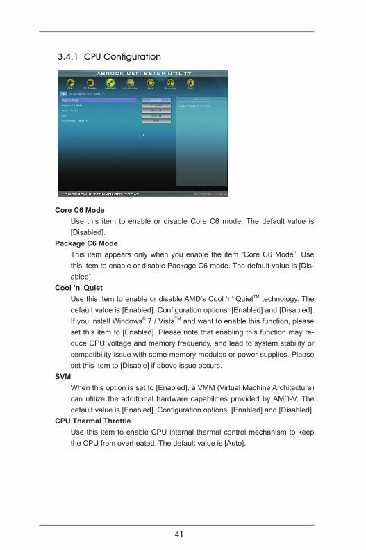
3.4.1 CPU Configuration
Core C6 Mode Use this item to enable or disable Core C6 mode. The default value is
[Disabled]. Package C6 Mode
This item appears only when you enable the item “Core C6 Mode”. Use this item to enable or disable Package C6 mode. The default value is [Dis-abled].
Cool ‘n’ Quiet Use this item to enable or disable AMD’s Cool ‘n’ QuietTM technology. The
default value is [Enabled]. Configuration options: [Enabled] and [Disabled]. If you install Windows® 7 / VistaTM and want to enable this function, please set this item to [Enabled]. Please note that enabling this function may re-duce CPU voltage and memory frequency, and lead to system stability or compatibility issue with some memory modules or power supplies. Please set this item to [Disable] if above issue occurs.
SVM When this option is set to [Enabled], a VMM (Virtual Machine Architecture)
can utilize the additional hardware capabilities provided by AMD-V. The default value is [Enabled]. Configuration options: [Enabled] and [Disabled].
CPU Thermal Throttle Use this item to enable CPU internal thermal control mechanism to keep
the CPU from overheated. The default value is [Auto].

42
3.4.2 North Bridge Configuration
Primary Graphics Adapter This item will switch the PCI Bus scanning order while searching for video
card. It allows you to select the type of Primary VGA in case of multiple video controllers. The default value of this feature is [PCI Express]. Con-figuration options: [Onboard], [PCI] and [PCI Express].
Share MemoryThis allows you to set the share memory feature. The default value is [Auto]. Configuration options: [Auto], [32MB], [64MB], [128MB], [256MB] and [512MB].
Onboard HDMI HD Audio This allows you to enable or disable the “Onboard HDMI HD Audio” fea-ture.
Dual Graphics This item appears only when you install AMD RADEON HD6670 / 6570
/ 6450 graphics card on this motherboard. Use this to enable or disable Dual Graphics feature. If you enable this option, the primary monitor will be onboard VGA. If you select [Auto], Dual Graphics function will be auto-matically enabled when you install AMD RADEON HD6670 / 6570 / 6450 graphics card. The default value is [Auto].

43
3.4.3 South Bridge Configuration
Onboard HD AudioSelect [Auto], [Enabled] or [Disabled] for the onboard HD Audio feature. If you select [Auto], the onboard HD Audio will be disabled when PCI Sound Card is plugged.Front Panel
Select [Auto] or [Disabled] for the onboard HD Audio Front Panel. Onboard LAN
This allows you to enable or disable the onboard LAN feature. Good Night LED
Enable this option to turn off Power LED and Port80 LED when the system is power on. The keyboard LED will also be turned off in S1, S3 and S4 state. The default value is [Auto].

44
3.4.4 Storage Configuration
SATA Controller Use this item to enable or disable the “SATA Controller” feature. SATA Mode
Use this item to adjust SATA Mode. The default value of this option is [IDE Mode]. Configuration options: [AHCI Mode], [RAID Mode] and [IDE Mode].
If you set this item to RAID mode, it is suggested to install SATA ODD driver on SATA_5 and SATA_6 ports.
SATA IDE Combined Mode This item is for SATA_5 and SATA_6 ports. Use this item to enable or dis-
able SATA IDE combined mode. The default value is [Enabled].
If you want to build RAID on SATA_5 and SATA_6 ports, please disable this item.
Hard Disk S.M.A.R.T. Use this item to enable or disable the S.M.A.R.T. (Self-Monitoring, Analy-
sis, and Reporting Technology) feature. Configuration options: [Disabled], [Auto], [Enabled].
45
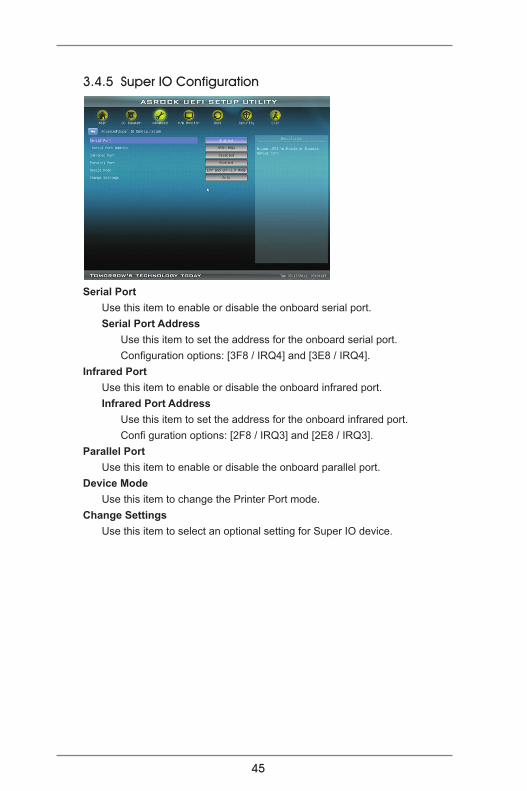
3.4.5 Super IO Configuration
Serial Port Use this item to enable or disable the onboard serial port. Serial Port Address Use this item to set the address for the onboard serial port. Configuration options: [3F8 / IRQ4] and [3E8 / IRQ4].Infrared Port Use this item to enable or disable the onboard infrared port. Infrared Port Address Use this item to set the address for the onboard infrared port. Confi guration options: [2F8 / IRQ3] and [2E8 / IRQ3].Parallel Port Use this item to enable or disable the onboard parallel port. Device Mode Use this item to change the Printer Port mode.Change Settings Use this item to select an optional setting for Super IO device.

46
3.4.6 ACPI Configuration
Suspend to RAMUse this item to select whether to auto-detect or disable the Suspend-to-RAM feature. Select [Auto] will enable this feature if the OS supports it.
Check Ready Bit Use this item to enable or disable the feature Check Ready Bit.
Restore on AC/Power LossThis allows you to set the power state after an unexpected AC/power loss. If [Power Off] is selected, the AC/power remains off when the power re-covers. If [Power On] is selected, the AC/power resumes and the system starts to boot up when the power recovers.
PS/2 Keyboard Power On Use this item to enable or disable PS/2 keyboard to turn on the system
from the power-soft-off mode.PCI Devices Power On Use this item to enable or disable PCI devices to turn on the system from
the power-soft-off mode. Ring-In Power On Use this item to enable or disable Ring-In signals to turn on the system
from the power-soft-off mode. RTC Alarm Power On Use this item to enable or disable RTC (Real Time Clock) to power on the
system.USB Keyboard/Remote Power On Use this item to enable or disable USB Keyboard/Remote to power on the
system.USB Mouse Power On Use this item to enable or disable USB Mouse to power on the system.

47
ACPI HPET table Use this item to enable or disable ACPI HPET Table. The default value is
[Enabled]. Please set this option to [Enabled] if you plan to use this moth-erboard to submit Windows® VistaTM certification.
48
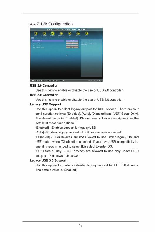
3.4.7 USB Configuration
USB 2.0 Controller Use this item to enable or disable the use of USB 2.0 controller.USB 3.0 Controller Use this item to enable or disable the use of USB 3.0 controller.Legacy USB Support Use this option to select legacy support for USB devices. There are four
confi guration options: [Enabled], [Auto], [Disabled] and [UEFI Setup Only]. The default value is [Enabled]. Please refer to below descriptions for the details of these four options:
[Enabled] - Enables support for legacy USB. [Auto] - Enables legacy support if USB devices are connected. [Disabled] - USB devices are not allowed to use under legacy OS and
UEFI setup when [Disabled] is selected. If you have USB compatibility is-sue, it is recommended to select [Disabled] to enter OS.
[UEFI Setup Only] - USB devices are allowed to use only under UEFI setup and Windows / Linux OS.
Legacy USB 3.0 Support Use this option to enable or disable legacy support for USB 3.0 devices.
The default value is [Enabled].

49
CPU Fan 1 Setting This allows you to set the CPU fan 1 speed. Confi guration options: [Full
On] and [Automatic Mode]. The default is value [Full On].Chassis Fan 1 Setting This allows you to set the chassis fan 1 speed. Confi guration options: [Full
On], [Manual Mode] and [Automatic Mode]. The default is value [Full On].
3.5 Hardware Health Event Monitoring ScreenIn this section, it allows you to monitor the status of the hardware on your system, including the parameters of the CPU temperature, motherboard temperature, CPU fan speed, chassis fan speed, and the critical voltage.
50
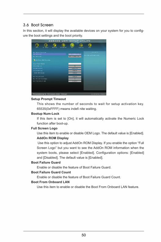
3.6 Boot ScreenIn this section, it will display the available devices on your system for you to config-ure the boot settings and the boot priority.
Setup Prompt Timeout This shows the number of seconds to wait for setup activation key.
65535(0xFFFF) means indefi nite waiting.Bootup Num-Lock If this item is set to [On], it will automatically activate the Numeric Lock
function after boot-up.Full Screen Logo Use this item to enable or disable OEM Logo. The default value is [Enabled]. AddOn ROM Display Use this option to adjust AddOn ROM Display. If you enable the option “Full
Screen Logo” but you want to see the AddOn ROM information when the system boots, please select [Enabled]. Configuration options: [Enabled] and [Disabled]. The default value is [Enabled].
Boot Failure Guard Enable or disable the feature of Boot Failure Guard.Boot Failure Guard Count Enable or disable the feature of Boot Failure Guard Count.Boot From Onboard LAN Use this item to enable or disable the Boot From Onboard LAN feature.

51
3.7 Security ScreenIn this section, you may set or change the supervisor/user password for the system. For the user password, you may also clear it.
52
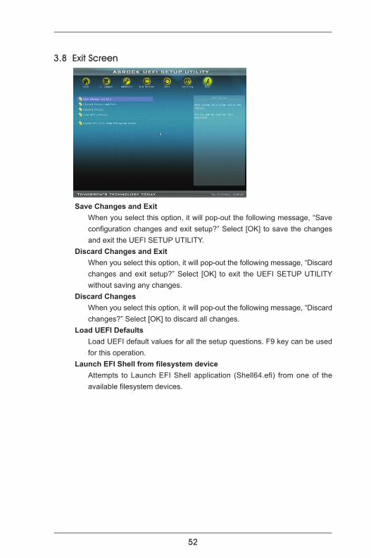
3.8 Exit Screen
Save Changes and ExitWhen you select this option, it will pop-out the following message, “Save configuration changes and exit setup?” Select [OK] to save the changes and exit the UEFI SETUP UTILITY.
Discard Changes and ExitWhen you select this option, it will pop-out the following message, “Discard changes and exit setup?” Select [OK] to exit the UEFI SETUP UTILITY without saving any changes.
Discard ChangesWhen you select this option, it will pop-out the following message, “Discard changes?” Select [OK] to discard all changes.
Load UEFI Defaults Load UEFI default values for all the setup questions. F9 key can be used for this operation.
Launch EFI Shell from filesystem deviceAttempts to Launch EFI Shell application (Shell64.efi) from one of the available filesystem devices.

53
4. Software Support 4.1 Install Operating System This motherboard supports various Microsoft® Windows® operating systems: 7 / 7 64-bit / VistaTM / VistaTM 64-bit / XP SP3 / XP 64-bit. Because motherboard settings and hardware options vary, use the setup procedures in this chapter for general reference only. Refer to your OS documentation for more information.
4.2 Support CD InformationThe Support CD that came with the motherboard contains necessary drivers and useful utilities that enhance the motherboard features.
4.2.1 Running The Support CD To begin using the support CD, insert the CD into your CD-ROM drive. The CD automatically displays the Main Menu if “AUTORUN” is enabled in your com-puter. If the Main Menu did not appear automatically, locate and double click on the file “ASSETUP.EXE” from the BIN folder in the Support CD to display the menus.
4.2.2 Drivers MenuThe Drivers Menu shows the available devices drivers if the system detects the installed devices. Please install the necessary drivers to activate the devices.
4.2.3 Utilities MenuThe Utilities Menu shows the applications software that the motherboard sup-ports. Click on a specific item then follow the installation wizard to install it.
4.2.4 Contact Information If you need to contact ASRock or want to know more about ASRock, welcome to visit ASRock’s website at http://www.asrock.com; or you may contact your dealer for further information.
54
Installing OS on a HDD Larger Than 2TBThis motherboard is adopting UEFI BIOS that allows Windows® OS to be installed on a large size HDD (>2TB). Please follow below procedure to install the operating system.
1. Please make sure to use Windows® VistaTM 64-bit (with SP1 or above) or Windows® 7 64-bit. 2. Press <F2> or <Delete> at system POST. Set AHCI Mode in UEFI Setup Utility > Advanced > Storage Configuration > SATA Mode. 3. Choose the item “UEFI:xxx“ to boot in UEFI Setup Utility > Boot > Boot Option #1. (“xxx” is the device which contains your Windows® installation files. Normally it is an optical drive.) You can also press <F11> to launch boot menu at system POST and choose the item “UEFI:xxx“ to boot. 4. Start Windows® installation.