Embed Size (px)
Citation preview

A4LDE Automatic Transmission
09/97 Scorpio ’95 00-01-1
A4LDE Automatic Transmission Assembly – Dismantle and Assemble (17 214 8)Special Tools
15008
15-008Dial indicator fixture
15–022 A
15-022ADial indicator fixture
15058
15-058Pinion seal installer
17002
17-002Installer, transmissionextension housing seal
17006B
17-006BMounting bracket
17007A
17-007ACompressor, clutch spring
17008
17-008Installer, shift lever seal
1700901A
17-009-01AAligner, transmission fluidpump
17010A
17-010AInstaller, transmission fluidpump seal
17011A
17-011ARemover, transmission fluidpump seal
17012
17-012Gauge, rear servo piston rod
17029
17-029Torque wrench, brake band
17030
17-030Aligner screws, control unit
17055
17-055Gauge bar
17058
17-058Spring compressor, clutch
17067
17-067Guide sleeve, one–wayclutch
17068
17-068Setting gauge, transmissionrange sensor
21179
21-179Separator, sump
Proprietary Tools
Dial indicator
Depth gauge
Workshop Equipment
Assembly stand
A4LDE Automatic Transmission
09/97 Scorpio ’95 00-01-2
Materials
Set of gaskets
Vaseline
Paraffin
ELJ1701101
Dismantle
NOTE: The torque converter is filled withautomatic transmission fluid.
1. Take out the torque converter.
� Shake the torque converter and pour thetransmission fluid through a very fine filter.
� Check the transmission fluid (see GeneralNotes).
ELJ1701102
2. Withdraw the input shaft.
ELS1701151
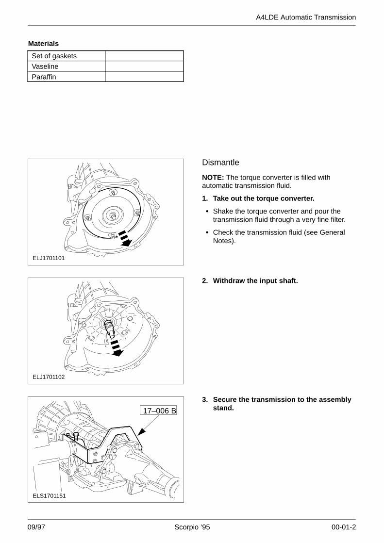
17–006 B
3. Secure the transmission to the assemblystand.
A4LDE Automatic Transmission
09/97 Scorpio ’95 00-01-3
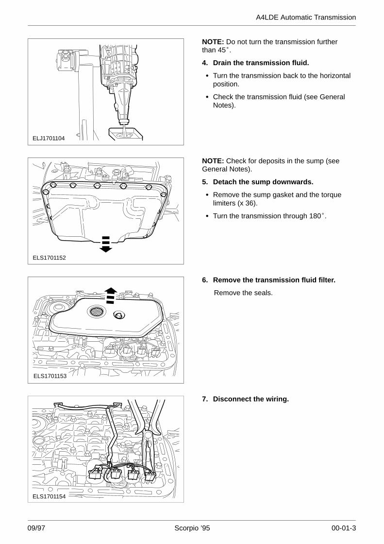
ELJ1701104
NOTE: Do not turn the transmission furtherthan 45�.
4. Drain the transmission fluid.
� Turn the transmission back to the horizontalposition.
� Check the transmission fluid (see GeneralNotes).
ELS1701152
NOTE: Check for deposits in the sump (seeGeneral Notes).
5. Detach the sump downwards.
� Remove the sump gasket and the torquelimiters (x 36).
� Turn the transmission through 180�.
ELS1701153
6. Remove the transmission fluid filter.
Remove the seals.
ELS1701154
7. Disconnect the wiring.
A4LDE Automatic Transmission
09/97 Scorpio ’95 00-01-4
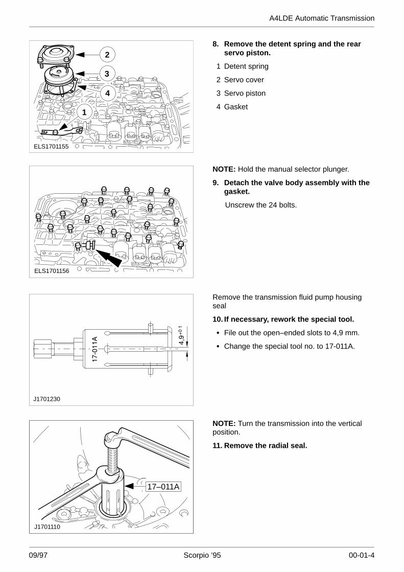
ELS1701155
1
4
3
28. Remove the detent spring and the rear
servo piston.
1 Detent spring
2 Servo cover
3 Servo piston
4 Gasket
ELS1701156
NOTE: Hold the manual selector plunger.
9. Detach the valve body assembly with thegasket.
Unscrew the 24 bolts.
J1701230
Remove the transmission fluid pump housingseal
10. If necessary, rework the special tool.
� File out the open–ended slots to 4,9 mm.
� Change the special tool no. to 17-011A.
17–011A
J1701110
NOTE: Turn the transmission into the verticalposition.
11. Remove the radial seal.
A4LDE Automatic Transmission
09/97 Scorpio ’95 00-01-5
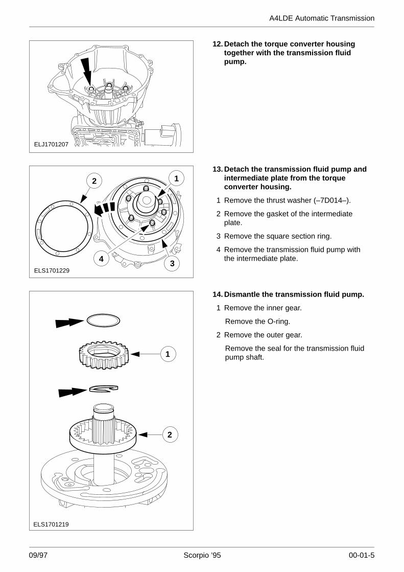
ELJ1701207
12. Detach the torque converter housingtogether with the transmission fluidpump.
ELS1701229
2 1
34
13. Detach the transmission fluid pump andintermediate plate from the torqueconverter housing.
1 Remove the thrust washer (–7D014–).
2 Remove the gasket of the intermediateplate.
3 Remove the square section ring.
4 Remove the transmission fluid pump withthe intermediate plate.
ELS1701219
1
2
14. Dismantle the transmission fluid pump.
1 Remove the inner gear.
Remove the O-ring.
2 Remove the outer gear.
Remove the seal for the transmission fluidpump shaft.
A4LDE Automatic Transmission
09/97 Scorpio ’95 00-01-6
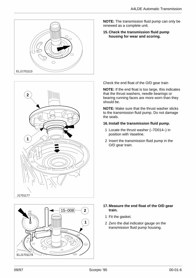
ELJ1701113
NOTE: The transmission fluid pump can only berenewed as a complete unit.
15. Check the transmission fluid pumphousing for wear and scoring.
1
2
J1701177
Check the end float of the O/D gear train
NOTE: If the end float is too large, this indicatesthat the thrust washers, needle bearings orbearing running faces are more worn than theyshould be.
NOTE: Make sure that the thrust washer sticksto the transmission fluid pump. Do not damagethe seals.
16. Install the transmission fluid pump.
1 Locate the thrust washer (–7D014–) inposition with Vaseline.
2 Insert the transmission fluid pump in theO/D gear train.
1
2
ELJ1701178
15–00817. Measure the end float of the O/D gear
train.
1 Fit the gasket.
2 Zero the dial indicator gauge on thetransmission fluid pump housing.
A4LDE Automatic Transmission
09/97 Scorpio ’95 00-01-7
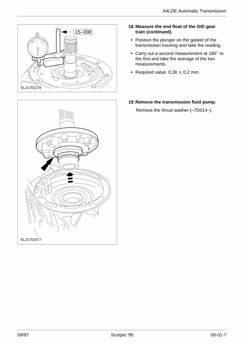
ELJ1701179
15–00818. Measure the end float of the O/D gear
train (continued).
� Position the plunger on the gasket of thetransmission housing and take the reading.
� Carry out a second measurement at 180� tothe first and take the average of the twomeasurements.
� Required value: 0,38 �� 0,2 mm.
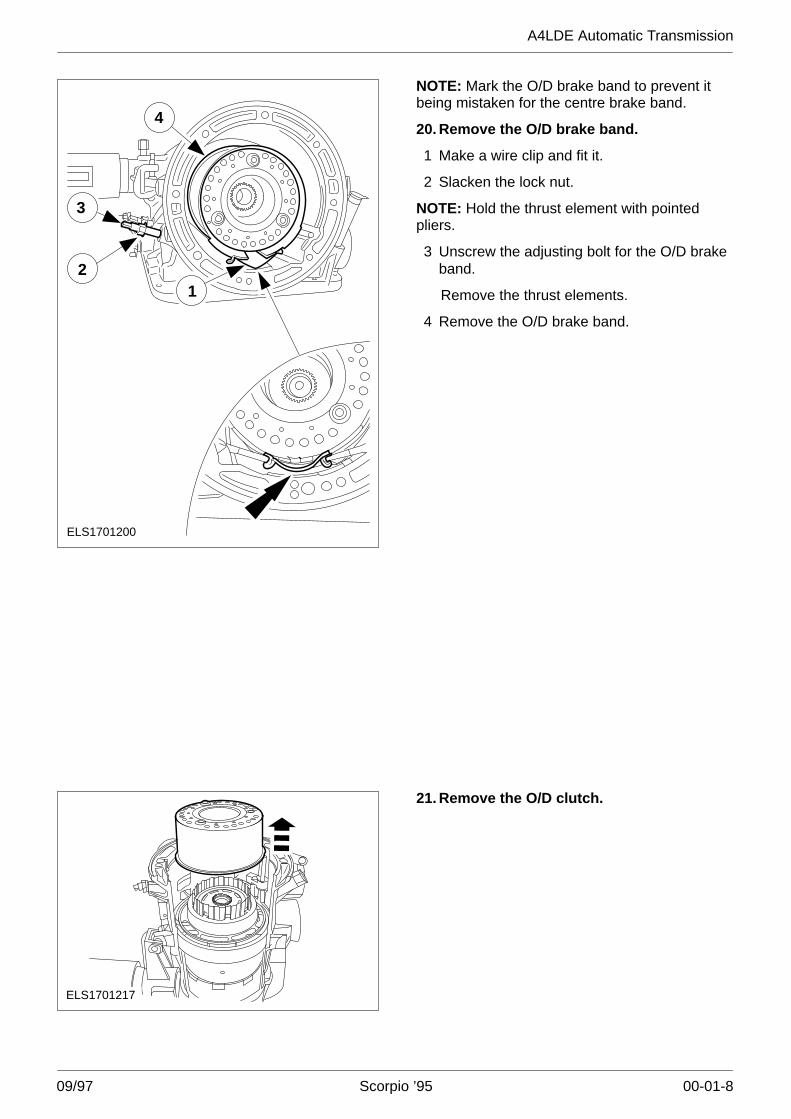
ELJ1701677
19. Remove the transmission fluid pump.
Remove the thrust washer (–7D014–).
A4LDE Automatic Transmission
09/97 Scorpio ’95 00-01-8
4
12
3
ELS1701200
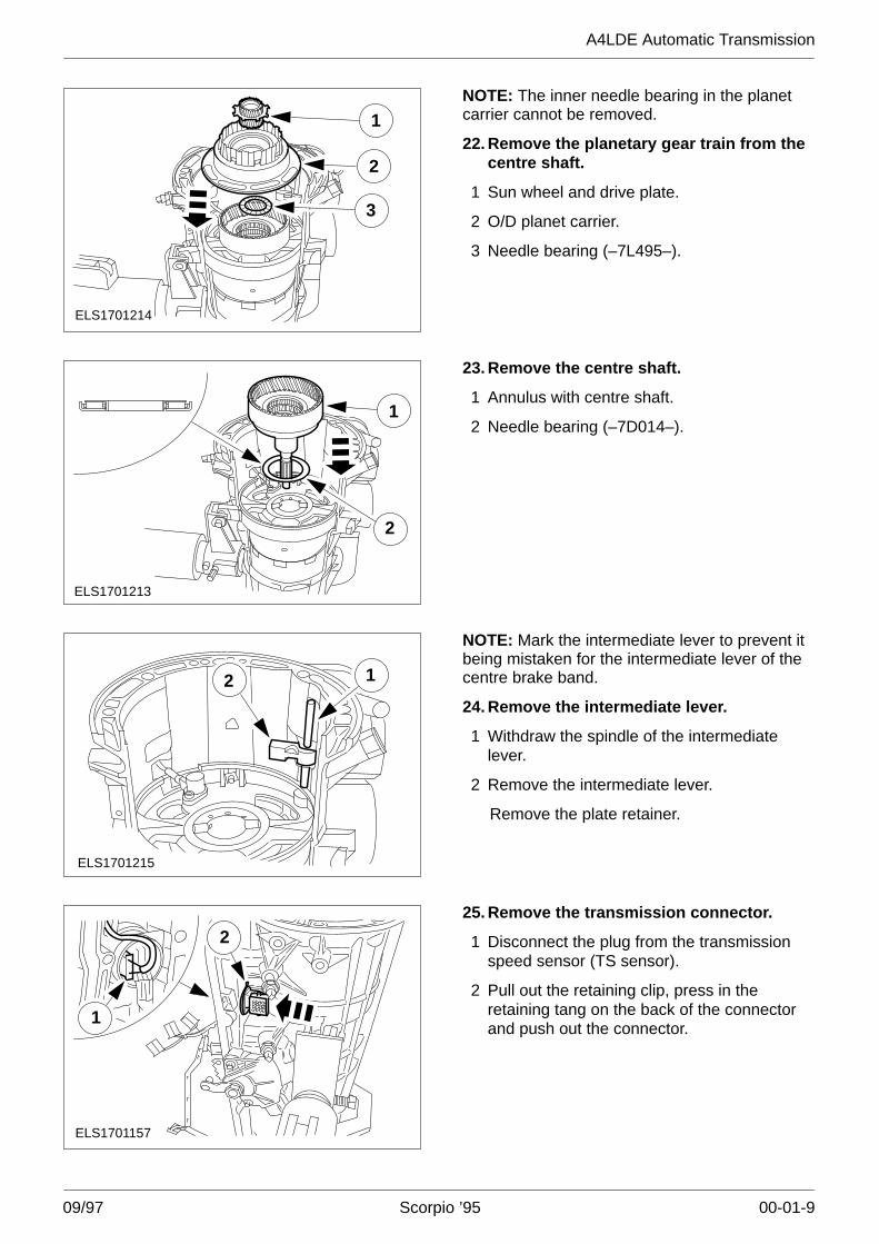
NOTE: Mark the O/D brake band to prevent itbeing mistaken for the centre brake band.
20. Remove the O/D brake band.
1 Make a wire clip and fit it.
2 Slacken the lock nut.
NOTE: Hold the thrust element with pointedpliers.
3 Unscrew the adjusting bolt for the O/D brakeband.
Remove the thrust elements.
4 Remove the O/D brake band.
ELS1701217
21. Remove the O/D clutch.
A4LDE Automatic Transmission
09/97 Scorpio ’95 00-01-9
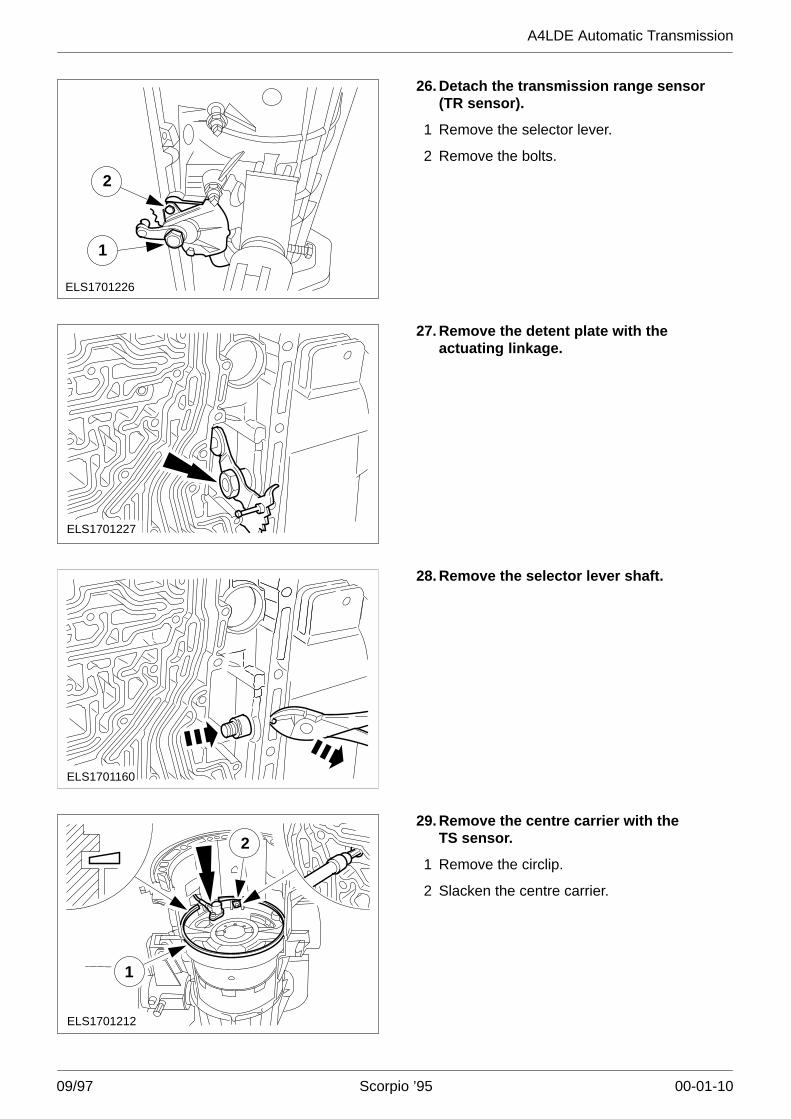
ELS1701214
3
2
1NOTE: The inner needle bearing in the planetcarrier cannot be removed.
22. Remove the planetary gear train from thecentre shaft.
1 Sun wheel and drive plate.
2 O/D planet carrier.
3 Needle bearing (–7L495–).
ELS1701213
1
2
23. Remove the centre shaft.
1 Annulus with centre shaft.
2 Needle bearing (–7D014–).
ELS1701215
2 1
NOTE: Mark the intermediate lever to prevent itbeing mistaken for the intermediate lever of thecentre brake band.
24. Remove the intermediate lever.
1 Withdraw the spindle of the intermediatelever.
2 Remove the intermediate lever.
Remove the plate retainer.
ELS1701157
2
1
25. Remove the transmission connector.
1 Disconnect the plug from the transmissionspeed sensor (TS sensor).
2 Pull out the retaining clip, press in theretaining tang on the back of the connectorand push out the connector.
A4LDE Automatic Transmission
09/97 Scorpio ’95 00-01-10
ELS1701226
1
2
26. Detach the transmission range sensor(TR sensor).
1 Remove the selector lever.
2 Remove the bolts.
ELS1701227
27. Remove the detent plate with theactuating linkage.
ELS1701160
28. Remove the selector lever shaft.
ELS1701212
1
229. Remove the centre carrier with the
TS sensor.
1 Remove the circlip.
2 Slacken the centre carrier.

A4LDE Automatic Transmission
09/97 Scorpio ’95 00-01-11
ELS1701211
1
2
30. Remove the centre carrier with theTS sensor (continued).
�CAUTION: Do not damage the TS sensorwiring.
1 Remove the centre carrier.
2 Needle bearing (–7D014–).
Remove the Viton seals from the centrecarrier.
ESS1701164
1
2
3
4NOTE: Mark the brake band to prevent it beingmistaken for the O/D brake band.
31. Remove the centre brake band.
1 Make a wire clip and fit it.
2 Slacken the lock nut.
3 Remove the adjusting bolt.
4 Remove the thrust elements with pointedpliers.
Remove the brake band.
ELS1701201
1
2
3
4
6
7
8
9
5
Remove the centre gear train.
32. Exploded view of centre gear train.
1 Reverse and direct drive clutch
2 Thrust washer (–7D428–)
3 Forward clutch
4 Needle bearing (–7D234–)
5 Bronze bush (–7D045–)
6 Annulus with hub
7 Needle bearing (–7F374–)
8 Front planet carrier
9 Input bell housing
A4LDE Automatic Transmission
09/97 Scorpio ’95 00-01-12
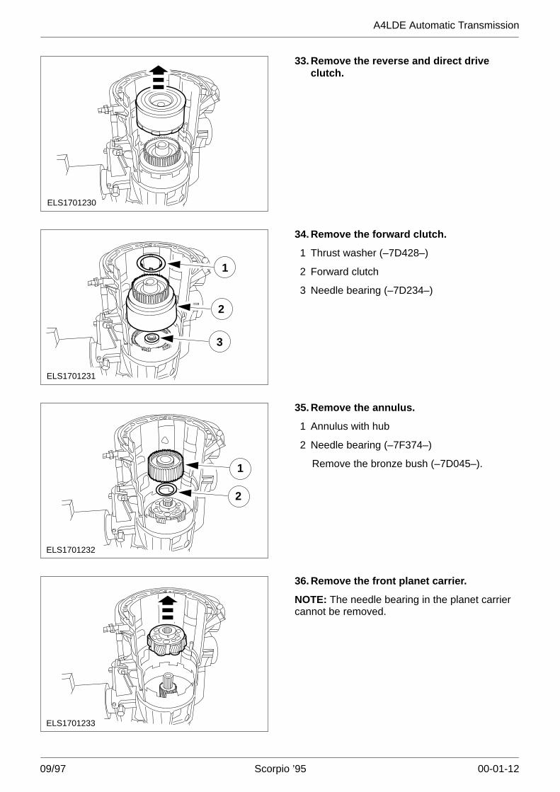
ELS1701230
33. Remove the reverse and direct driveclutch.
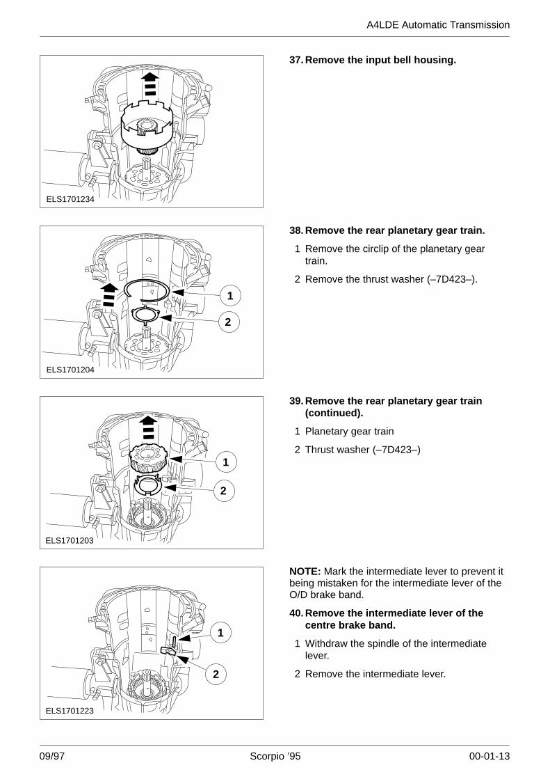
ELS1701231
2
1
3
34. Remove the forward clutch.
1 Thrust washer (–7D428–)
2 Forward clutch
3 Needle bearing (–7D234–)
2
1
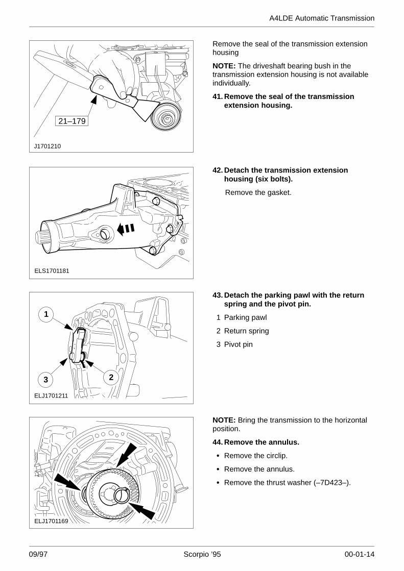
ELS1701232
35. Remove the annulus.
1 Annulus with hub
2 Needle bearing (–7F374–)
Remove the bronze bush (–7D045–).
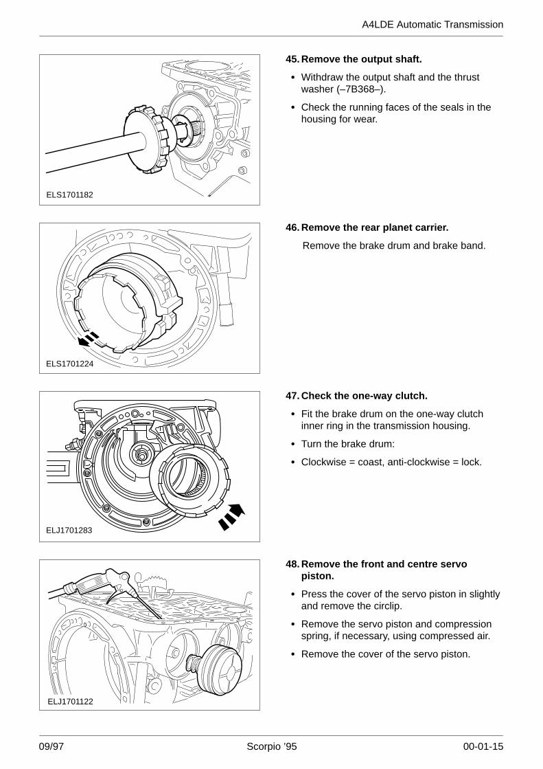
ELS1701233
36. Remove the front planet carrier.
NOTE: The needle bearing in the planet carriercannot be removed.
A4LDE Automatic Transmission
09/97 Scorpio ’95 00-01-13
ELS1701234
37. Remove the input bell housing.
ELS1701204
2
1
38. Remove the rear planetary gear train.
1 Remove the circlip of the planetary geartrain.
2 Remove the thrust washer (–7D423–).
ELS1701203
1
2
39. Remove the rear planetary gear train(continued).
1 Planetary gear train
2 Thrust washer (–7D423–)
ELS1701223
2
1
NOTE: Mark the intermediate lever to prevent itbeing mistaken for the intermediate lever of theO/D brake band.
40. Remove the intermediate lever of thecentre brake band.
1 Withdraw the spindle of the intermediatelever.
2 Remove the intermediate lever.
A4LDE Automatic Transmission
09/97 Scorpio ’95 00-01-14
J1701210
21–179
Remove the seal of the transmission extensionhousing
NOTE: The driveshaft bearing bush in thetransmission extension housing is not availableindividually.
41. Remove the seal of the transmissionextension housing.
ELS1701181
42. Detach the transmission extensionhousing (six bolts).
Remove the gasket.
ELJ1701211
3
1
2
43. Detach the parking pawl with the returnspring and the pivot pin.
1 Parking pawl
2 Return spring
3 Pivot pin
ELJ1701169
NOTE: Bring the transmission to the horizontalposition.
44. Remove the annulus.
� Remove the circlip.
� Remove the annulus.
� Remove the thrust washer (–7D423–).
A4LDE Automatic Transmission
09/97 Scorpio ’95 00-01-15
ELS1701182
45. Remove the output shaft.
� Withdraw the output shaft and the thrustwasher (–7B368–).
� Check the running faces of the seals in thehousing for wear.
ELS1701224
46. Remove the rear planet carrier.
Remove the brake drum and brake band.
ELJ1701283
47. Check the one-way clutch.
� Fit the brake drum on the one-way clutchinner ring in the transmission housing.
� Turn the brake drum:
� Clockwise = coast, anti-clockwise = lock.
ELJ1701122
48. Remove the front and centre servopiston.
� Press the cover of the servo piston in slightlyand remove the circlip.
� Remove the servo piston and compressionspring, if necessary, using compressed air.
� Remove the cover of the servo piston.
A4LDE Automatic Transmission
09/97 Scorpio ’95 00-01-16
1
ELJ1701164
2
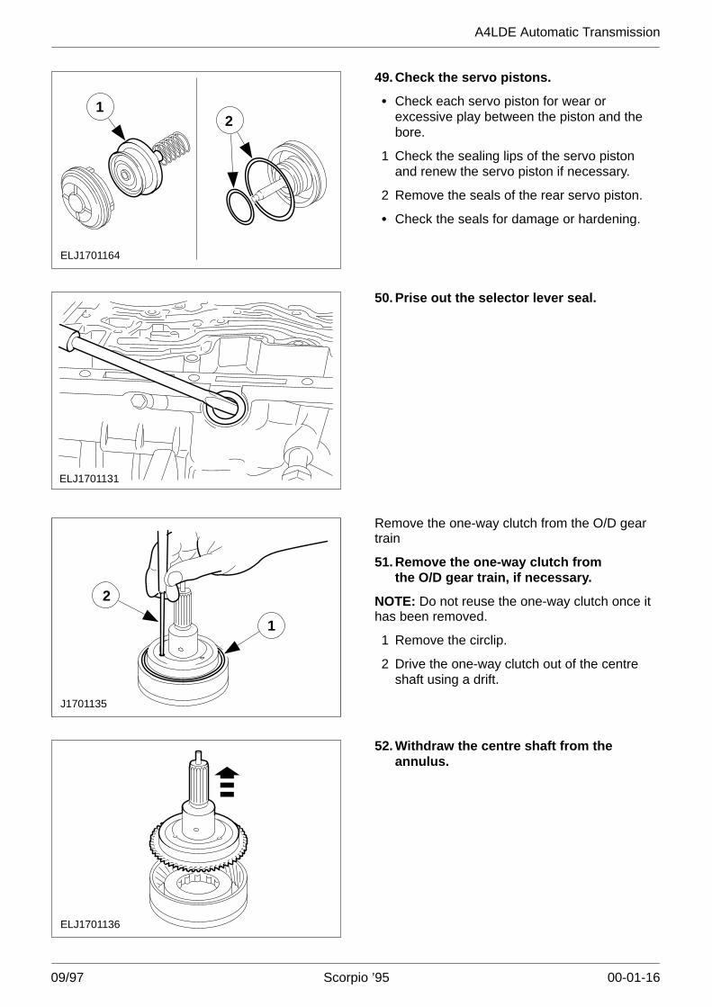
49. Check the servo pistons.
� Check each servo piston for wear orexcessive play between the piston and thebore.
1 Check the sealing lips of the servo pistonand renew the servo piston if necessary.
2 Remove the seals of the rear servo piston.
� Check the seals for damage or hardening.
ELJ1701131
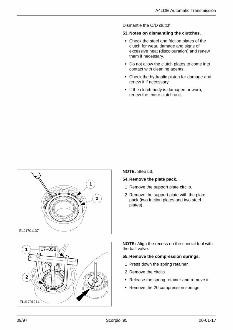
50. Prise out the selector lever seal.
J1701135
1
2
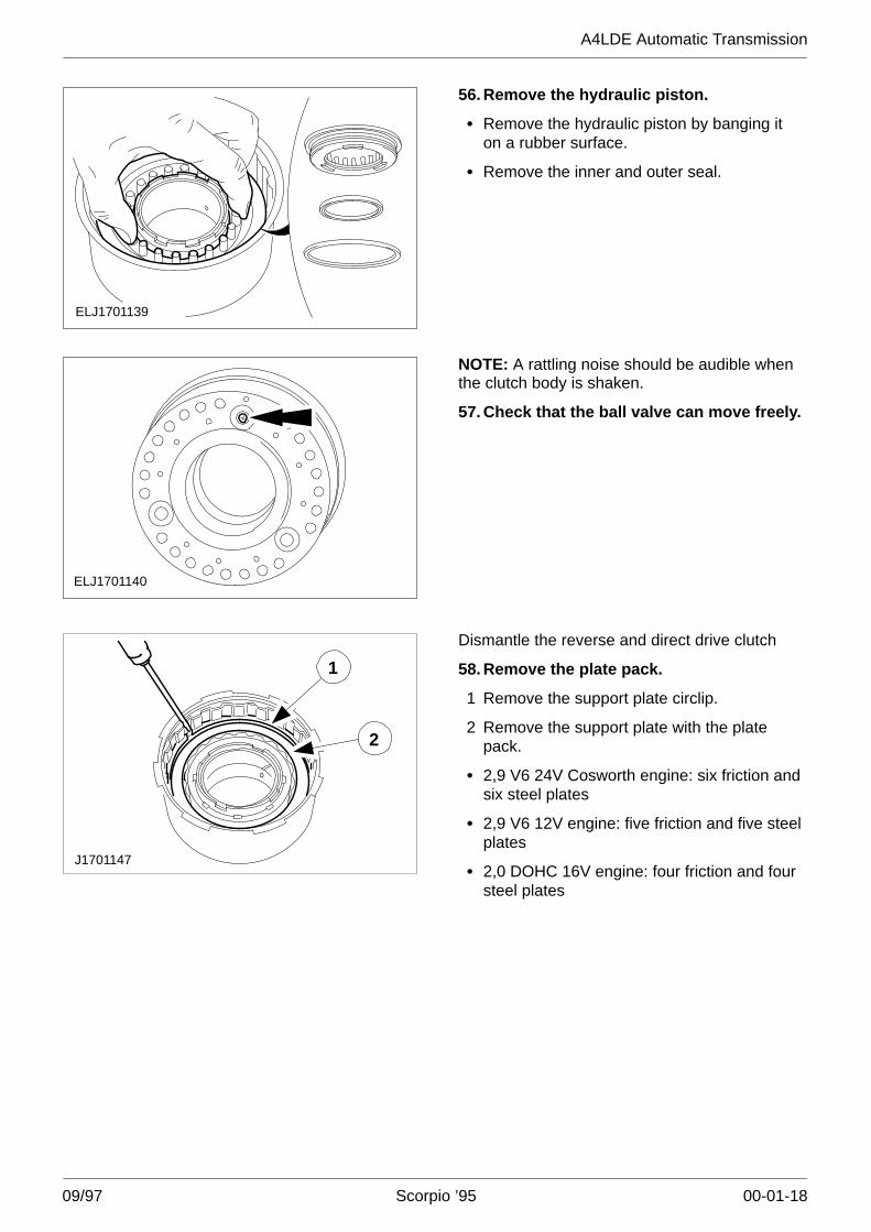
Remove the one-way clutch from the O/D geartrain
51. Remove the one-way clutch fromthe O/D gear train, if necessary.
NOTE: Do not reuse the one-way clutch once ithas been removed.
1 Remove the circlip.
2 Drive the one-way clutch out of the centreshaft using a drift.
ELJ1701136
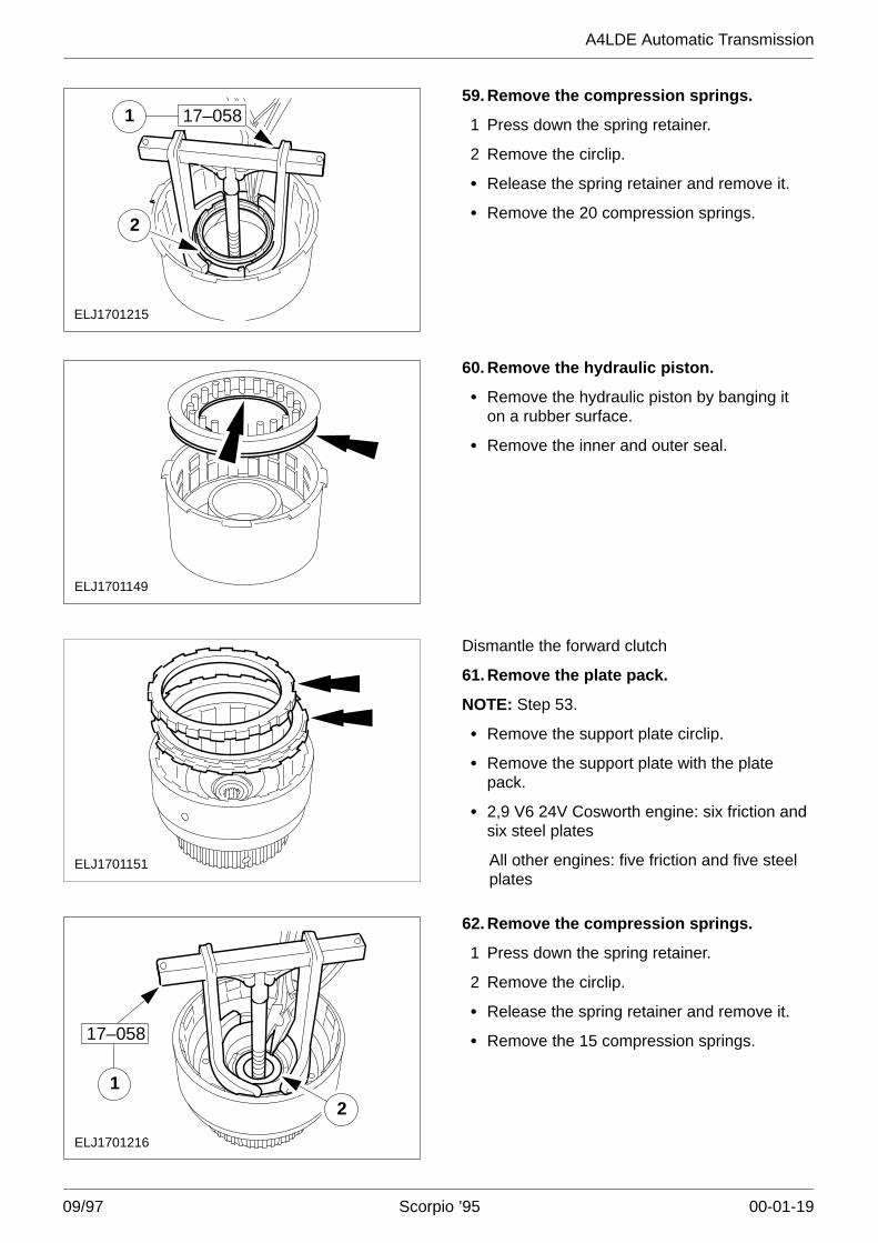
52. Withdraw the centre shaft from theannulus.
A4LDE Automatic Transmission
09/97 Scorpio ’95 00-01-17
Dismantle the O/D clutch
53. Notes on dismantling the clutches.
� Check the steel and friction plates of theclutch for wear, damage and signs ofexcessive heat (discolouration) and renewthem if necessary.
� Do not allow the clutch plates to come intocontact with cleaning agents.
� Check the hydraulic piston for damage andrenew it if necessary.
� If the clutch body is damaged or worn,renew the entire clutch unit.
ELJ1701137
1
2
NOTE: Step 53.
54. Remove the plate pack.
1 Remove the support plate circlip.
2 Remove the support plate with the platepack (two friction plates and two steelplates).
ELJ1701214
1
2
17–058NOTE: Align the recess on the special tool withthe ball valve.
55. Remove the compression springs.
1 Press down the spring retainer.
2 Remove the circlip.
� Release the spring retainer and remove it.
� Remove the 20 compression springs.
A4LDE Automatic Transmission
09/97 Scorpio ’95 00-01-18
ELJ1701139
56. Remove the hydraulic piston.
� Remove the hydraulic piston by banging iton a rubber surface.
� Remove the inner and outer seal.
ELJ1701140
NOTE: A rattling noise should be audible whenthe clutch body is shaken.
57. Check that the ball valve can move freely.
2
1
J1701147
Dismantle the reverse and direct drive clutch
58. Remove the plate pack.
1 Remove the support plate circlip.
2 Remove the support plate with the platepack.
� 2,9 V6 24V Cosworth engine: six friction andsix steel plates
� 2,9 V6 12V engine: five friction and five steelplates
� 2,0 DOHC 16V engine: four friction and foursteel plates
A4LDE Automatic Transmission
09/97 Scorpio ’95 00-01-19
ELJ1701215
2
17–058159. Remove the compression springs.
1 Press down the spring retainer.
2 Remove the circlip.
� Release the spring retainer and remove it.
� Remove the 20 compression springs.
ELJ1701149
60. Remove the hydraulic piston.
� Remove the hydraulic piston by banging iton a rubber surface.
� Remove the inner and outer seal.
ELJ1701151
Dismantle the forward clutch
61. Remove the plate pack.
NOTE: Step 53.
� Remove the support plate circlip.
� Remove the support plate with the platepack.
� 2,9 V6 24V Cosworth engine: six friction andsix steel plates
All other engines: five friction and five steelplates
ELJ1701216
21
17–058
62. Remove the compression springs.
1 Press down the spring retainer.
2 Remove the circlip.
� Release the spring retainer and remove it.
� Remove the 15 compression springs.
A4LDE Automatic Transmission
09/97 Scorpio ’95 00-01-20
ELJ1701153
1
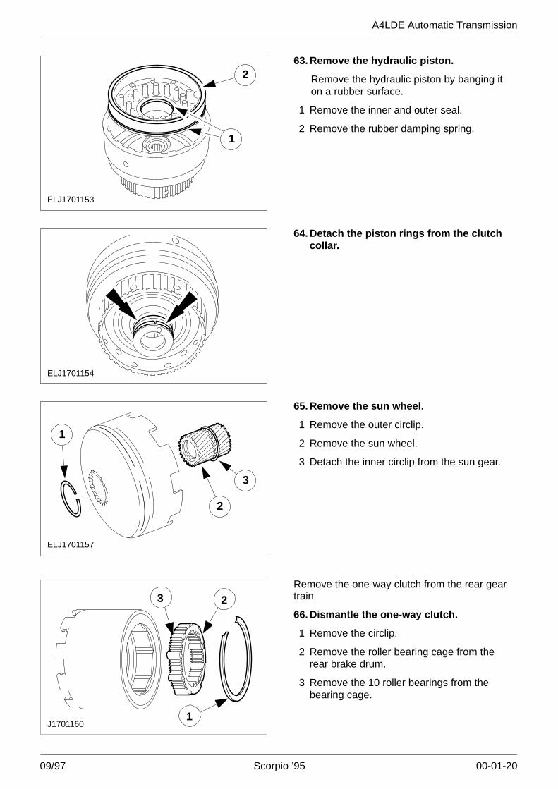
263. Remove the hydraulic piston.
Remove the hydraulic piston by banging iton a rubber surface.
1 Remove the inner and outer seal.
2 Remove the rubber damping spring.
ELJ1701154
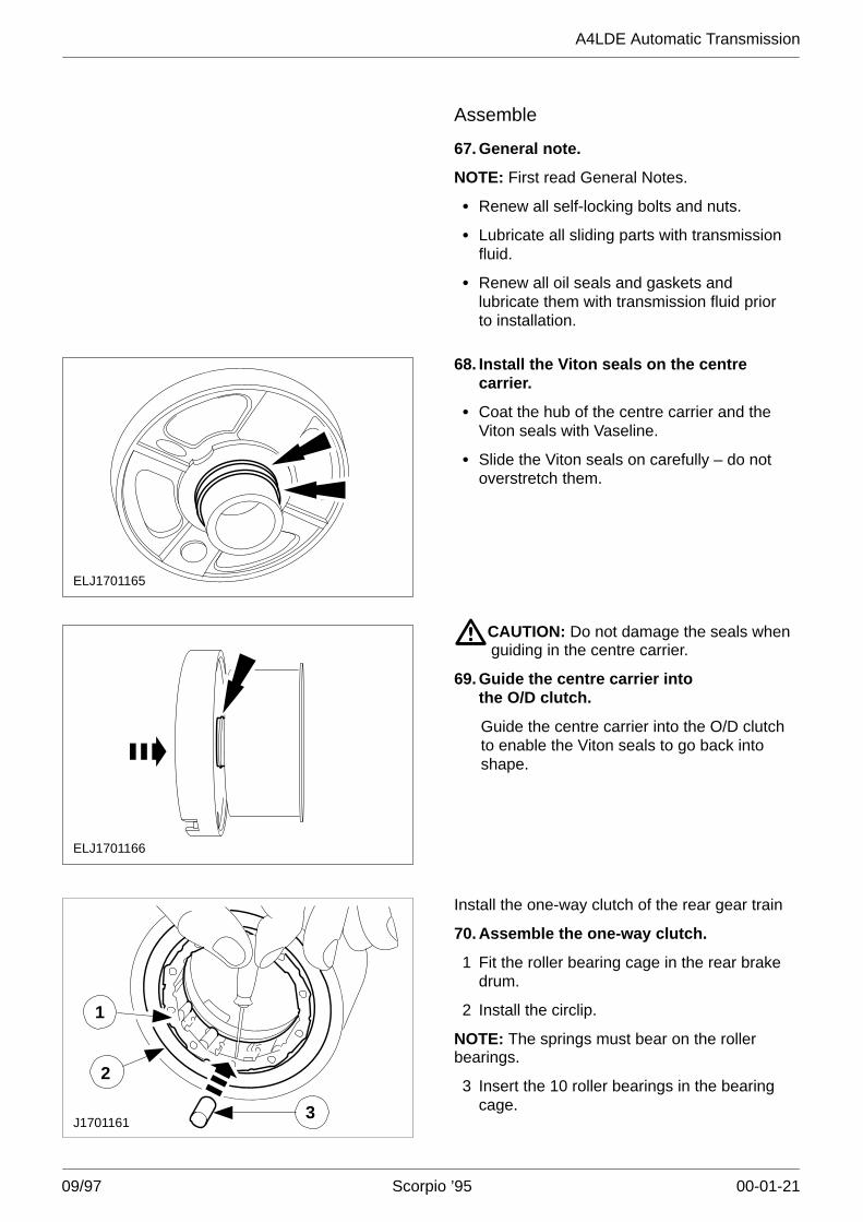
64. Detach the piston rings from the clutchcollar.
ELJ1701157
3
1
2
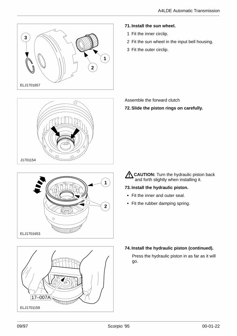
65. Remove the sun wheel.
1 Remove the outer circlip.
2 Remove the sun wheel.
3 Detach the inner circlip from the sun gear.
J17011601
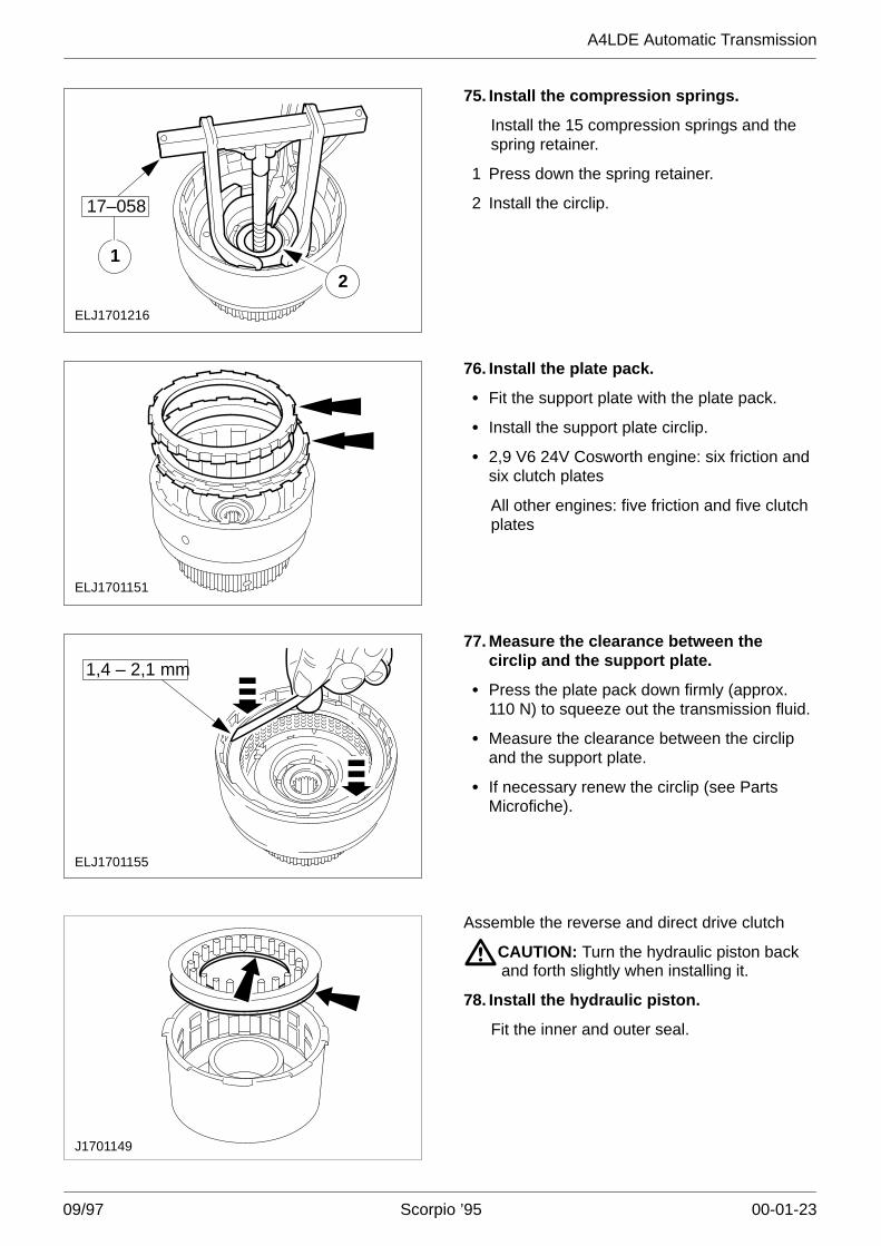
23Remove the one-way clutch from the rear geartrain
66. Dismantle the one-way clutch.
1 Remove the circlip.
2 Remove the roller bearing cage from therear brake drum.
3 Remove the 10 roller bearings from thebearing cage.
A4LDE Automatic Transmission
09/97 Scorpio ’95 00-01-21
Assemble
67. General note.
NOTE: First read General Notes.
� Renew all self-locking bolts and nuts.
� Lubricate all sliding parts with transmissionfluid.
� Renew all oil seals and gaskets andlubricate them with transmission fluid priorto installation.
ELJ1701165
68. Install the Viton seals on the centrecarrier.
� Coat the hub of the centre carrier and theViton seals with Vaseline.
� Slide the Viton seals on carefully – do notoverstretch them.
ELJ1701166
�CAUTION: Do not damage the seals whenguiding in the centre carrier.
69. Guide the centre carrier intothe O/D clutch.
Guide the centre carrier into the O/D clutchto enable the Viton seals to go back intoshape.
1
3J1701161
2
Install the one-way clutch of the rear gear train
70. Assemble the one-way clutch.
1 Fit the roller bearing cage in the rear brakedrum.
2 Install the circlip.
NOTE: The springs must bear on the rollerbearings.
3 Insert the 10 roller bearings in the bearingcage.
A4LDE Automatic Transmission
09/97 Scorpio ’95 00-01-22
2
ELJ1701657
3
1
71. Install the sun wheel.
1 Fit the inner circlip.
2 Fit the sun wheel in the input bell housing.
3 Fit the outer circlip.
J1701154
Assemble the forward clutch
72. Slide the piston rings on carefully.
ELJ1701653
1
2
�CAUTION: Turn the hydraulic piston backand forth slightly when installing it.
73. Install the hydraulic piston.
� Fit the inner and outer seal.
� Fit the rubber damping spring.
ELJ1701159
17–007A
74. Install the hydraulic piston (continued).
Press the hydraulic piston in as far as it willgo.
A4LDE Automatic Transmission
09/97 Scorpio ’95 00-01-23
ELJ1701216
21
17–058
75. Install the compression springs.
Install the 15 compression springs and thespring retainer.
1 Press down the spring retainer.
2 Install the circlip.
ELJ1701151
76. Install the plate pack.
� Fit the support plate with the plate pack.
� Install the support plate circlip.
� 2,9 V6 24V Cosworth engine: six friction andsix clutch plates
All other engines: five friction and five clutchplates
ELJ1701155
1,4 – 2,1 mm
77. Measure the clearance between thecirclip and the support plate.
� Press the plate pack down firmly (approx.110 N) to squeeze out the transmission fluid.
� Measure the clearance between the circlipand the support plate.
� If necessary renew the circlip (see PartsMicrofiche).
J1701149
Assemble the reverse and direct drive clutch
�CAUTION: Turn the hydraulic piston backand forth slightly when installing it.
78. Install the hydraulic piston.
Fit the inner and outer seal.
A4LDE Automatic Transmission
09/97 Scorpio ’95 00-01-24
ELJ1701215
2
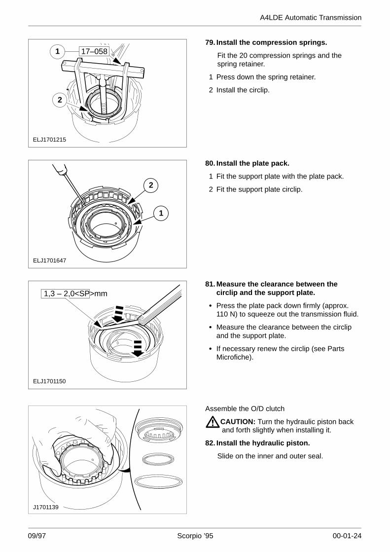
17–058179. Install the compression springs.
Fit the 20 compression springs and thespring retainer.
1 Press down the spring retainer.
2 Install the circlip.
ELJ1701647
2
1
80. Install the plate pack.
1 Fit the support plate with the plate pack.
2 Fit the support plate circlip.
1,3 – 2,0<SP>mm
ELJ1701150
81. Measure the clearance between thecirclip and the support plate.
� Press the plate pack down firmly (approx.110 N) to squeeze out the transmission fluid.
� Measure the clearance between the circlipand the support plate.
� If necessary renew the circlip (see PartsMicrofiche).
J1701139
Assemble the O/D clutch
�CAUTION: Turn the hydraulic piston backand forth slightly when installing it.
82. Install the hydraulic piston.
Slide on the inner and outer seal.
A4LDE Automatic Transmission
09/97 Scorpio ’95 00-01-25
ELJ1701214
1
2
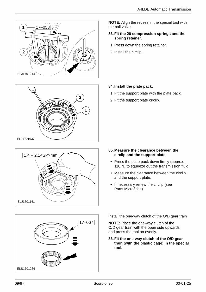
17–058NOTE: Align the recess in the special tool withthe ball valve.
83. Fit the 20 compression springs and thespring retainer.
1 Press down the spring retainer.
2 Install the circlip.
ELJ1701637
2
1
84. Install the plate pack.
1 Fit the support plate with the plate pack.
2 Fit the support plate circlip.
ELJ1701141
1,4 – 2,1<SP>mm85. Measure the clearance between the
circlip and the support plate.
� Press the plate pack down firmly (approx.110 N) to squeeze out the transmission fluid.
� Measure the clearance between the circlipand the support plate.
� If necessary renew the circlip (seeParts Microfiche).
ELS1701236
17–067
Install the one-way clutch of the O/D gear train
NOTE: Place the one-way clutch of the O/D gear train with the open side upwardsand press the tool on evenly.
86. Fit the one-way clutch of the O/D geartrain (with the plastic cage) in the specialtool.
A4LDE Automatic Transmission
09/97 Scorpio ’95 00-01-26
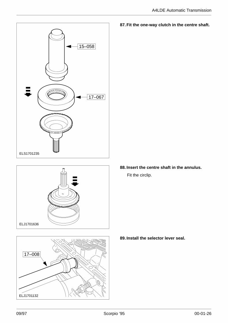
17–067
ELS1701235
15–058
87. Fit the one-way clutch in the centre shaft.
ELJ1701636
88. Insert the centre shaft in the annulus.
Fit the circlip.
ELJ1701132
17–008
89. Install the selector lever seal.
A4LDE Automatic Transmission
09/97 Scorpio ’95 00-01-27
ELS1701183
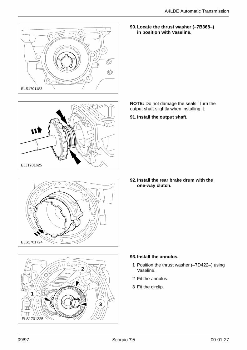
90. Locate the thrust washer (–7B368–)in position with Vaseline.
ELJ1701625
NOTE: Do not damage the seals. Turn theoutput shaft slightly when installing it.
91. Install the output shaft.
ELS1701724
92. Install the rear brake drum with theone-way clutch.
ELS1701225
3
2
1
93. Install the annulus.
1 Position the thrust washer (–7D422–) usingVaseline.
2 Fit the annulus.
3 Fit the circlip.
A4LDE Automatic Transmission
09/97 Scorpio ’95 00-01-28
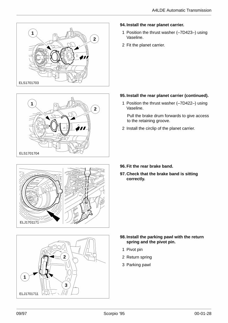
ELS1701703
12
94. Install the rear planet carrier.
1 Position the thrust washer (–7D423–) usingVaseline.
2 Fit the planet carrier.
ELS1701704
21
95. Install the rear planet carrier (continued).
1 Position the thrust washer (–7D422–) usingVaseline.
Pull the brake drum forwards to give accessto the retaining groove.
2 Install the circlip of the planet carrier.
ELJ1701171
96. Fit the rear brake band.
97. Check that the brake band is sittingcorrectly.
ELJ1701711
1
3
2
98. Install the parking pawl with the returnspring and the pivot pin.
1 Pivot pin
2 Return spring
3 Parking pawl
A4LDE Automatic Transmission
09/97 Scorpio ’95 00-01-29
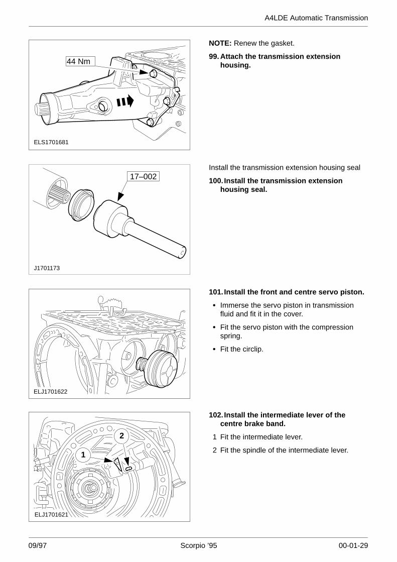
ELS1701681
44 Nm
NOTE: Renew the gasket.
99. Attach the transmission extensionhousing.
J1701173
17–002Install the transmission extension housing seal
100. Install the transmission extensionhousing seal.
ELJ1701622
101. Install the front and centre servo piston.
� Immerse the servo piston in transmissionfluid and fit it in the cover.
� Fit the servo piston with the compressionspring.
� Fit the circlip.
ELJ1701621
1
2
102. Install the intermediate lever of thecentre brake band.
1 Fit the intermediate lever.
2 Fit the spindle of the intermediate lever.
A4LDE Automatic Transmission
09/97 Scorpio ’95 00-01-30
ELS1701701
1
2
3
4
5
6
7
9
8
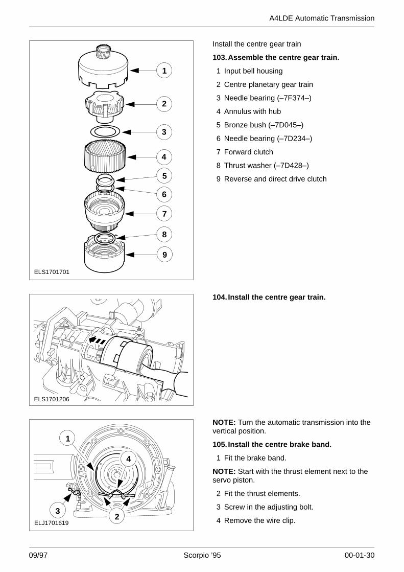
Install the centre gear train
103.Assemble the centre gear train.
1 Input bell housing
2 Centre planetary gear train
3 Needle bearing (–7F374–)
4 Annulus with hub
5 Bronze bush (–7D045–)
6 Needle bearing (–7D234–)
7 Forward clutch
8 Thrust washer (–7D428–)
9 Reverse and direct drive clutch
ELS1701206
104. Install the centre gear train.
ELJ1701619
3
1
4
2
NOTE: Turn the automatic transmission into thevertical position.
105. Install the centre brake band.
1 Fit the brake band.
NOTE: Start with the thrust element next to theservo piston.
2 Fit the thrust elements.
3 Screw in the adjusting bolt.
4 Remove the wire clip.
A4LDE Automatic Transmission
09/97 Scorpio ’95 00-01-31
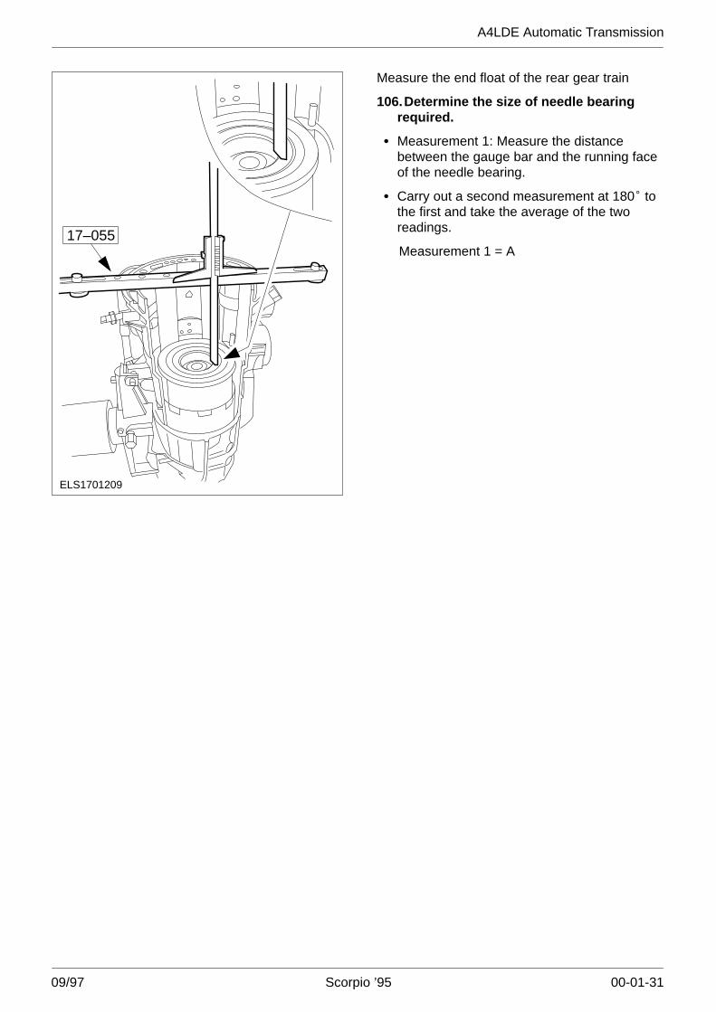
17–055
ELS1701209
Measure the end float of the rear gear train
106.Determine the size of needle bearingrequired.
� Measurement 1: Measure the distancebetween the gauge bar and the running faceof the needle bearing.
� Carry out a second measurement at 180� tothe first and take the average of the tworeadings.
Measurement 1 = A
A4LDE Automatic Transmission
09/97 Scorpio ’95 00-01-32
ELS1701208
17–055
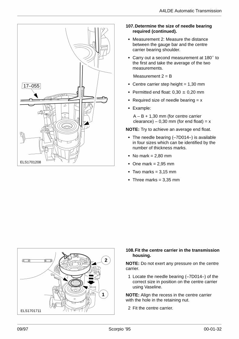
107.Determine the size of needle bearingrequired (continued).
� Measurement 2: Measure the distancebetween the gauge bar and the centrecarrier bearing shoulder.
� Carry out a second measurement at 180� tothe first and take the average of the twomeasurements.
Measurement 2 = B
� Centre carrier step height = 1,30 mm
� Permitted end float: 0,30 �� 0,20 mm
� Required size of needle bearing = x
� Example:
A – B + 1,30 mm (for centre carrierclearance) – 0,30 mm (for end float) = x
NOTE: Try to achieve an average end float.
� The needle bearing (–7D014–) is availablein four sizes which can be identified by thenumber of thickness marks.
� No mark = 2,80 mm
� One mark = 2,95 mm
� Two marks = 3,15 mm
� Three marks = 3,35 mm
ELS1701711
1
2
108.Fit the centre carrier in the transmissionhousing.
NOTE: Do not exert any pressure on the centrecarrier.
1 Locate the needle bearing (–7D014–) of thecorrect size in position on the centre carrierusing Vaseline.
NOTE: Align the recess in the centre carrierwith the hole in the retaining nut.
2 Fit the centre carrier.
A4LDE Automatic Transmission
09/97 Scorpio ’95 00-01-33
ELJ1701194
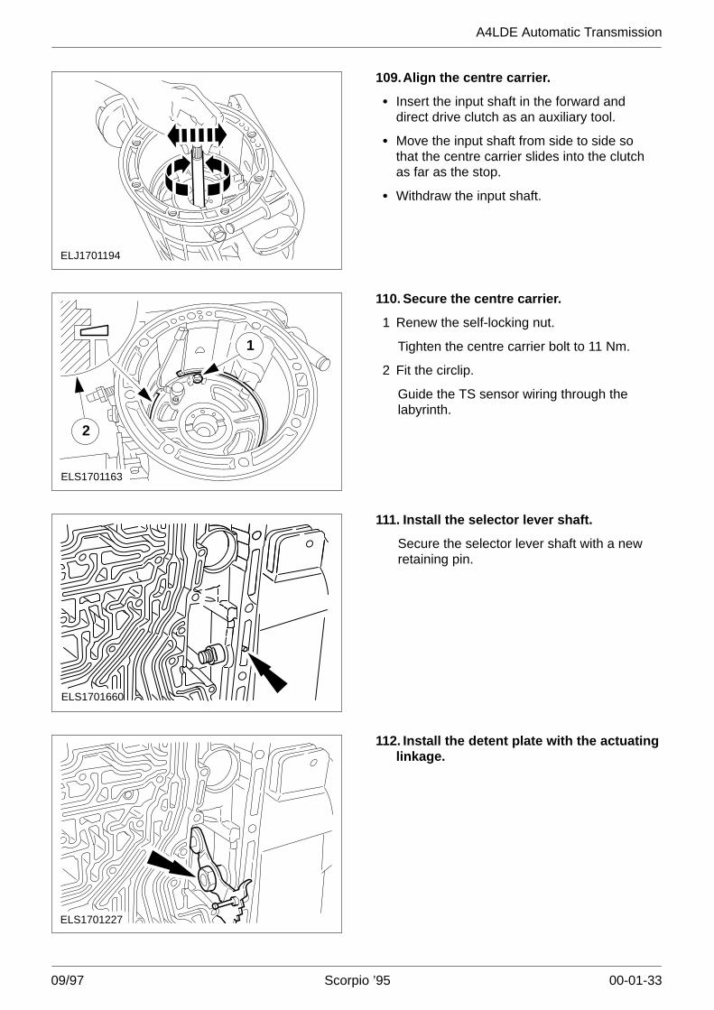
109.Align the centre carrier.
� Insert the input shaft in the forward anddirect drive clutch as an auxiliary tool.
� Move the input shaft from side to side sothat the centre carrier slides into the clutchas far as the stop.
� Withdraw the input shaft.
2
ELS1701163
1
110. Secure the centre carrier.
1 Renew the self-locking nut.
Tighten the centre carrier bolt to 11 Nm.
2 Fit the circlip.
Guide the TS sensor wiring through thelabyrinth.
ELS1701660
111. Install the selector lever shaft.
Secure the selector lever shaft with a newretaining pin.
ELS1701227
112. Install the detent plate with the actuatinglinkage.
A4LDE Automatic Transmission
09/97 Scorpio ’95 00-01-34
ELS1701726
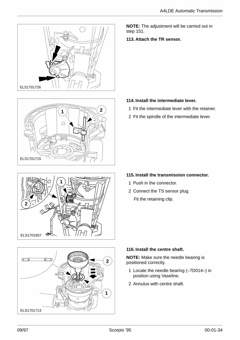
NOTE: The adjustment will be carried out instep 151.
113. Attach the TR sensor.
ELS1701715
1 2
114. Install the intermediate lever.
1 Fit the intermediate lever with the retainer.
2 Fit the spindle of the intermediate lever.
ELS1701657
2
1115. Install the transmission connector.
1 Push in the connector.
2 Connect the TS sensor plug.
Fit the retaining clip.
ELS1701713
2
1
116. Install the centre shaft.
NOTE: Make sure the needle bearing ispositioned correctly.
1 Locate the needle bearing (–7D014–) inposition using Vaseline.
2 Annulus with centre shaft.
A4LDE Automatic Transmission
09/97 Scorpio ’95 00-01-35
ELS1701714
1
2
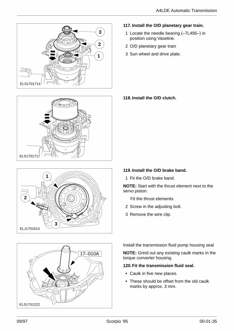
3117. Install the O/D planetary gear train.
1 Locate the needle bearing (–7L495–) inposition using Vaseline.
2 O/D planetary gear train
3 Sun wheel and drive plate.
ELS1701717
118. Install the O/D clutch.
ELJ1701614
1
2
3
119. Install the O/D brake band.
1 Fit the O/D brake band.
NOTE: Start with the thrust element next to theservo piston.
Fit the thrust elements.
2 Screw in the adjusting bolt.
3 Remove the wire clip.
ELS1701222
17–010A
Install the transmission fluid pump housing seal
NOTE: Grind out any existing caulk marks in thetorque converter housing.
120.Fit the transmission fluid seal.
� Caulk in five new places.
� These should be offset from the old caulkmarks by approx. 3 mm.
A4LDE Automatic Transmission
09/97 Scorpio ’95 00-01-36
1
2
J1701177
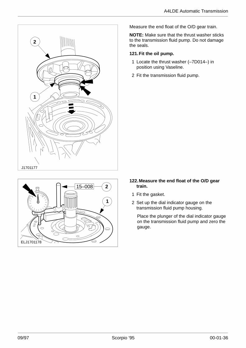
Measure the end float of the O/D gear train.
NOTE: Make sure that the thrust washer sticksto the transmission fluid pump. Do not damagethe seals.
121.Fit the oil pump.
1 Locate the thrust washer (–7D014–) inposition using Vaseline.
2 Fit the transmission fluid pump.
1
2
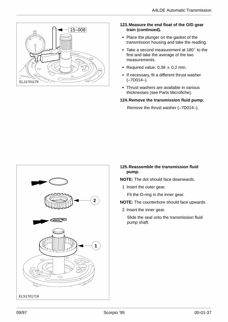
ELJ1701178
15–008122.Measure the end float of the O/D gear
train.
1 Fit the gasket.
2 Set up the dial indicator gauge on thetransmission fluid pump housing.
Place the plunger of the dial indicator gaugeon the transmission fluid pump and zero thegauge.
A4LDE Automatic Transmission
09/97 Scorpio ’95 00-01-37
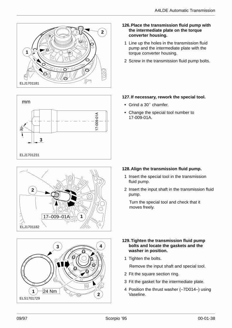
ELJ1701179
15–008123.Measure the end float of the O/D gear
train (continued).
� Place the plunger on the gasket of thetransmission housing and take the reading.
� Take a second measurement at 180� to thefirst and take the average of the twomeasurements.
� Required value: 0,38 �� 0,2 mm.
� If necessary, fit a different thrust washer(–7D014–).
� Thrust washers are available in variousthicknesses (see Parts Microfiche).
124.Remove the transmission fluid pump.
Remove the thrust washer (–7D014–).
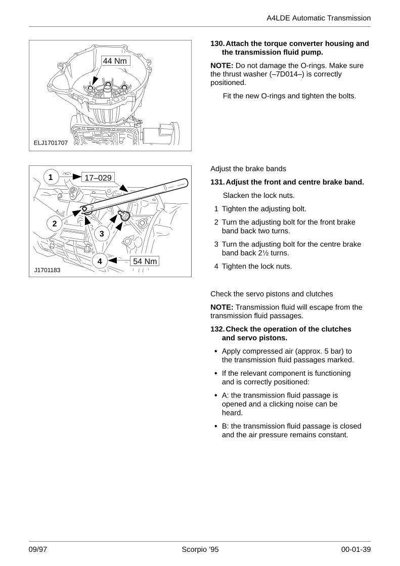
ELS1701719
1
2
125.Reassemble the transmission fluidpump.
NOTE: The dot should face downwards.
1 Insert the outer gear.
Fit the O-ring in the inner gear.
NOTE: The counterbore should face upwards.
2 Insert the inner gear.
Slide the seal onto the transmission fluidpump shaft.
A4LDE Automatic Transmission
09/97 Scorpio ’95 00-01-38
ELJ1701181
2
1
126.Place the transmission fluid pump withthe intermediate plate on the torqueconverter housing.
1 Line up the holes in the transmission fluidpump and the intermediate plate with thetorque converter housing.
2 Screw in the transmission fluid pump bolts.
3
ELJ1701231
mm127. If necessary, rework the special tool.
� Grind a 30� chamfer.
� Change the special tool number to17-009-01A.
ELJ1701182
2
17–009–01A 1
128.Align the transmission fluid pump.
1 Insert the special tool in the transmissionfluid pump.
2 Insert the input shaft in the transmission fluidpump.
Turn the special tool and check that itmoves freely.
ELS1701729
4
2
3
1 24 Nm
129.Tighten the transmission fluid pumpbolts and locate the gaskets and thewasher in position.
1 Tighten the bolts.
Remove the input shaft and special tool.
2 Fit the square section ring.
3 Fit the gasket for the intermediate plate.
4 Position the thrust washer (–7D014–) usingVaseline.
A4LDE Automatic Transmission
09/97 Scorpio ’95 00-01-39
ELJ1701707
44 Nm
130.Attach the torque converter housing andthe transmission fluid pump.
NOTE: Do not damage the O-rings. Make surethe thrust washer (–7D014–) is correctlypositioned.
Fit the new O-rings and tighten the bolts.
J1701183
1 17–029
2
54 Nm4
3
Adjust the brake bands
131.Adjust the front and centre brake band.
Slacken the lock nuts.
1 Tighten the adjusting bolt.
2 Turn the adjusting bolt for the front brakeband back two turns.
3 Turn the adjusting bolt for the centre brakeband back 2� turns.
4 Tighten the lock nuts.
Check the servo pistons and clutches
NOTE: Transmission fluid will escape from thetransmission fluid passages.
132.Check the operation of the clutchesand servo pistons.
� Apply compressed air (approx. 5 bar) tothe transmission fluid passages marked.
� If the relevant component is functioningand is correctly positioned:
� A: the transmission fluid passage isopened and a clicking noise can beheard.
� B: the transmission fluid passage is closedand the air pressure remains constant.
A4LDE Automatic Transmission
09/97 Scorpio ’95 00-01-40
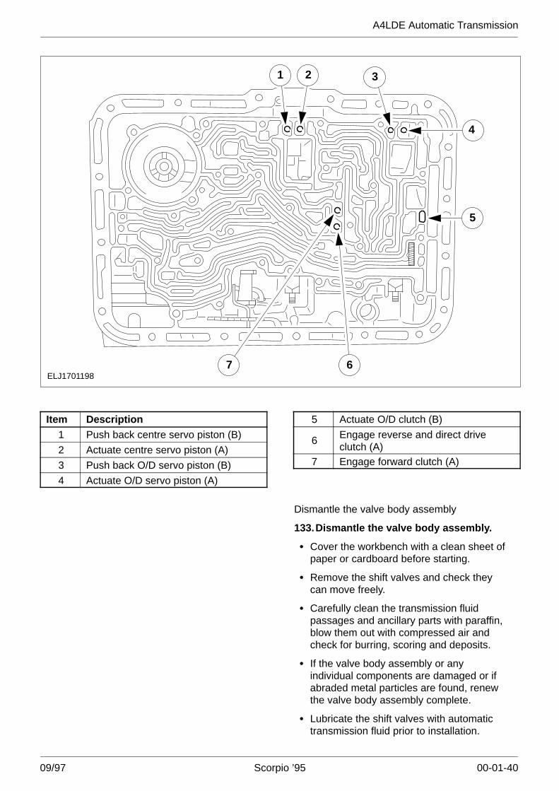
ELJ1701198
3
5
4
7 6
21
Item Description1 Push back centre servo piston (B)
2 Actuate centre servo piston (A)
3 Push back O/D servo piston (B)
4 Actuate O/D servo piston (A)
5 Actuate O/D clutch (B)
6 Engage reverse and direct driveclutch (A)
7 Engage forward clutch (A)
Dismantle the valve body assembly
133.Dismantle the valve body assembly.
� Cover the workbench with a clean sheet ofpaper or cardboard before starting.
� Remove the shift valves and check theycan move freely.
� Carefully clean the transmission fluidpassages and ancillary parts with paraffin,blow them out with compressed air andcheck for burring, scoring and deposits.
� If the valve body assembly or anyindividual components are damaged or ifabraded metal particles are found, renewthe valve body assembly complete.
� Lubricate the shift valves with automatictransmission fluid prior to installation.
A4LDE Automatic Transmission
09/97 Scorpio ’95 00-01-41
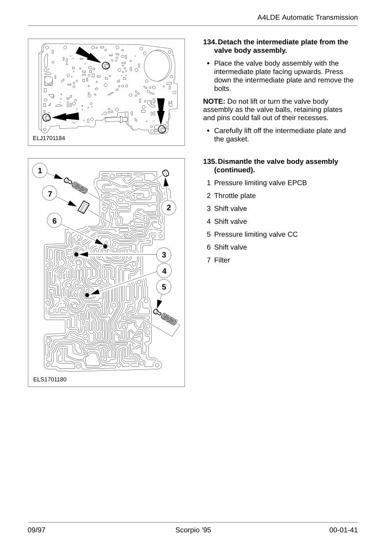
ELJ1701184
134.Detach the intermediate plate from thevalve body assembly.
� Place the valve body assembly with theintermediate plate facing upwards. Pressdown the intermediate plate and remove thebolts.
NOTE: Do not lift or turn the valve bodyassembly as the valve balls, retaining platesand pins could fall out of their recesses.
� Carefully lift off the intermediate plate andthe gasket.
ELS1701180
2
3
4
5
6
7
1135.Dismantle the valve body assembly
(continued).
1 Pressure limiting valve EPCB
2 Throttle plate
3 Shift valve
4 Shift valve
5 Pressure limiting valve CC
6 Shift valve
7 Filter
A4LDE Automatic Transmission
09/97 Scorpio ’95 00-01-42
ELS17012285
67
9
10
11
83
4
2
1
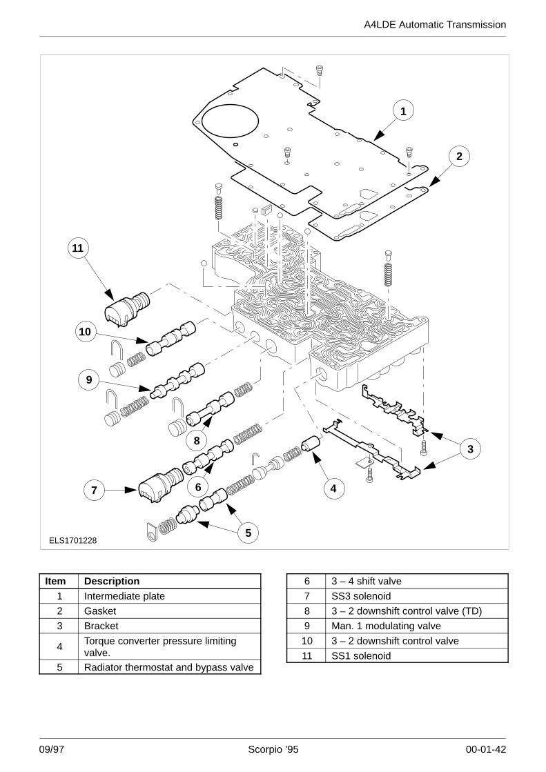
Item Description1 Intermediate plate
2 Gasket
3 Bracket
4 Torque converter pressure limitingvalve.
5 Radiator thermostat and bypass valve
6 3 – 4 shift valve
7 SS3 solenoid
8 3 – 2 downshift control valve (TD)
9 Man. 1 modulating valve
10 3 – 2 downshift control valve
11 SS1 solenoid
A4LDE Automatic Transmission
09/97 Scorpio ’95 00-01-43
ELS1701186
11
9
8
6
7
5
3
4
2
1
10
1213
14
15
16
17
18
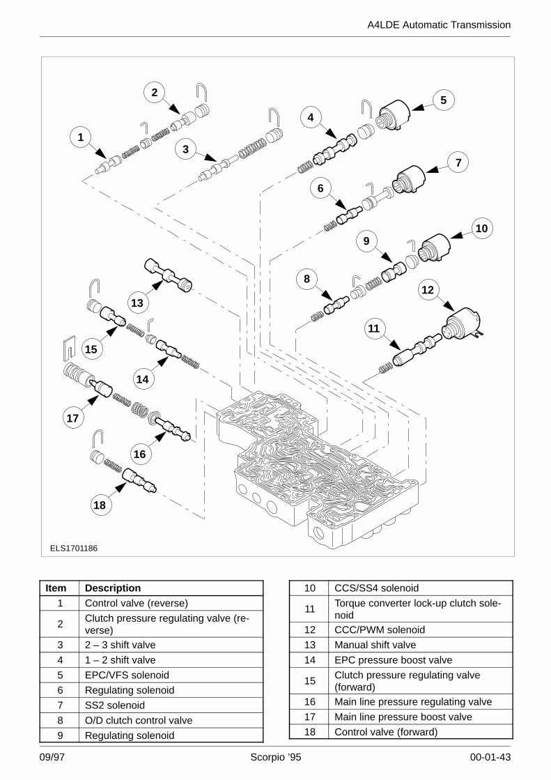
Item Description1 Control valve (reverse)
2 Clutch pressure regulating valve (re-verse)
3 2 – 3 shift valve
4 1 – 2 shift valve
5 EPC/VFS solenoid
6 Regulating solenoid
7 SS2 solenoid
8 O/D clutch control valve
9 Regulating solenoid
10 CCS/SS4 solenoid
11 Torque converter lock-up clutch sole-noid
12 CCC/PWM solenoid
13 Manual shift valve
14 EPC pressure boost valve
15 Clutch pressure regulating valve(forward)
16 Main line pressure regulating valve
17 Main line pressure boost valve
18 Control valve (forward)
A4LDE Automatic Transmission
09/97 Scorpio ’95 00-01-44
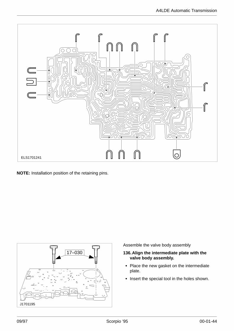
ELS1701241
NOTE: Installation position of the retaining pins.
17–030
J1701195
Assemble the valve body assembly
136.Align the intermediate plate with thevalve body assembly.
� Place the new gasket on the intermediateplate.
� Insert the special tool in the holes shown.
A4LDE Automatic Transmission
09/97 Scorpio ’95 00-01-45
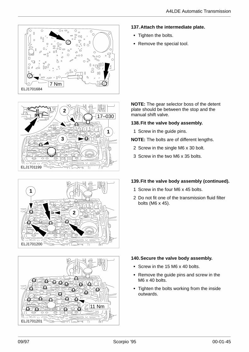
ELJ17016847 Nm
137.Attach the intermediate plate.
� Tighten the bolts.
� Remove the special tool.
3
217–030
1
ELJ1701199
NOTE: The gear selector boss of the detentplate should be between the stop and themanual shift valve.
138.Fit the valve body assembly.
1 Screw in the guide pins.
NOTE: The bolts are of different lengths.
2 Screw in the single M6 x 30 bolt.
3 Screw in the two M6 x 35 bolts.
2
ELJ1701200
1
139.Fit the valve body assembly (continued).
1 Screw in the four M6 x 45 bolts.
2 Do not fit one of the transmission fluid filterbolts (M6 x 45).
ELJ1701201
11 Nm
140.Secure the valve body assembly.
� Screw in the 15 M6 x 40 bolts.
� Remove the guide pins and screw in theM6 x 40 bolts.
� Tighten the bolts working from the insideoutwards.
A4LDE Automatic Transmission
09/97 Scorpio ’95 00-01-46
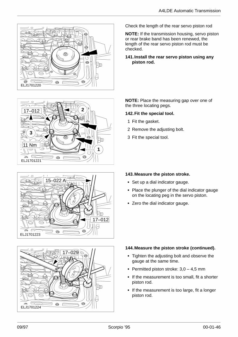
ELJ1701220
Check the length of the rear servo piston rod
NOTE: If the transmission housing, servo pistonor rear brake band has been renewed, thelength of the rear servo piston rod must bechecked.
141. Install the rear servo piston using anypiston rod.
111 Nm
ELJ1701221
17–012
3
2
NOTE: Place the measuring gap over one ofthe three locating pegs.
142.Fit the special tool.
1 Fit the gasket.
2 Remove the adjusting bolt.
3 Fit the special tool.
17–012
15–022 A
ELJ1701223
143.Measure the piston stroke.
� Set up a dial indicator gauge.
� Place the plunger of the dial indicator gaugeon the locating peg in the servo piston.
� Zero the dial indicator gauge.
ELJ1701224
17–029144.Measure the piston stroke (continued).
� Tighten the adjusting bolt and observe thegauge at the same time.
� Permitted piston stroke: 3,0 – 4,5 mm
� If the measurement is too small, fit a shorterpiston rod.
� If the measurement is too large, fit a longerpiston rod.
A4LDE Automatic Transmission
09/97 Scorpio ’95 00-01-47
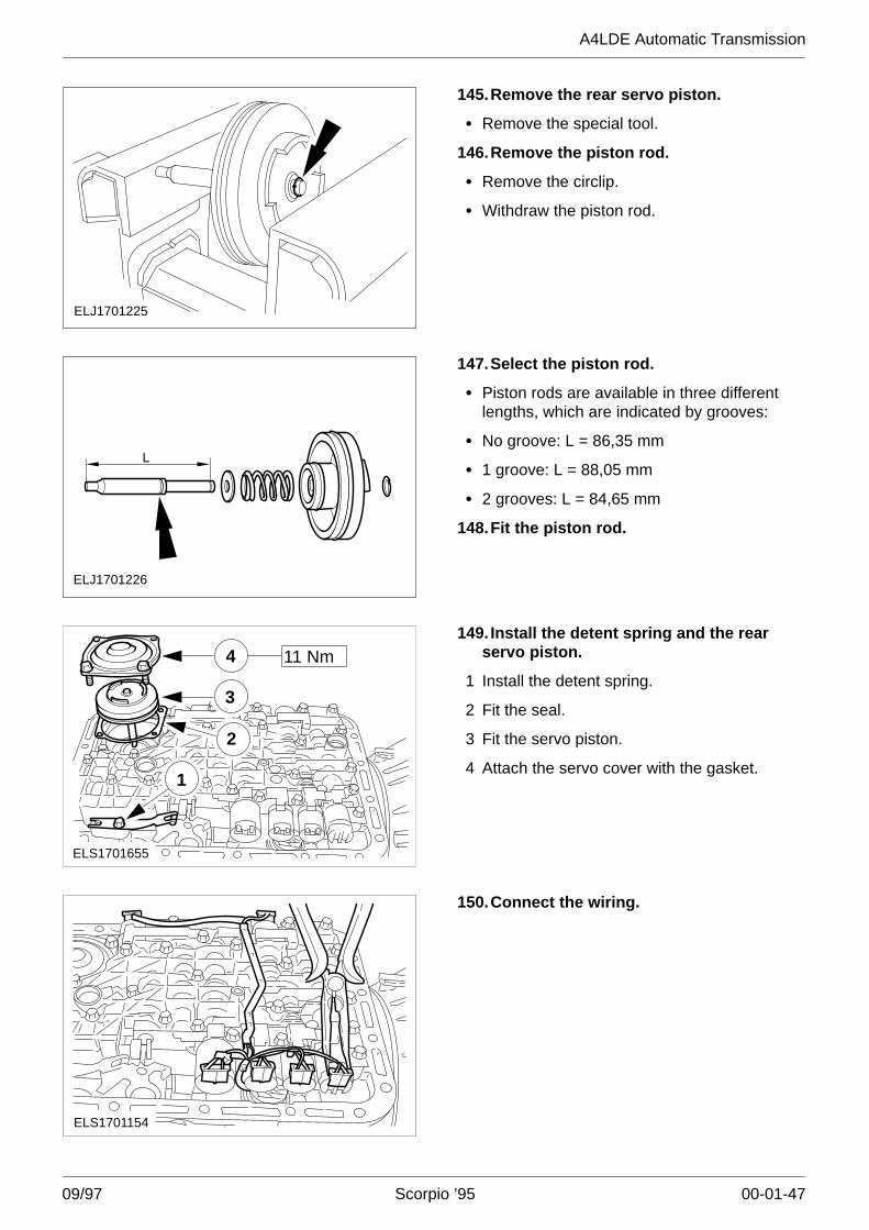
ELJ1701225
145.Remove the rear servo piston.
� Remove the special tool.
146.Remove the piston rod.
� Remove the circlip.
� Withdraw the piston rod.
ELJ1701226
L
147.Select the piston rod.
� Piston rods are available in three differentlengths, which are indicated by grooves:
� No groove: L = 86,35 mm
� 1 groove: L = 88,05 mm
� 2 grooves: L = 84,65 mm
148.Fit the piston rod.
ELS1701655
1
3
2
4 11 Nm149. Install the detent spring and the rear
servo piston.
1 Install the detent spring.
2 Fit the seal.
3 Fit the servo piston.
4 Attach the servo cover with the gasket.
ELS1701154
150.Connect the wiring.
A4LDE Automatic Transmission
09/97 Scorpio ’95 00-01-48
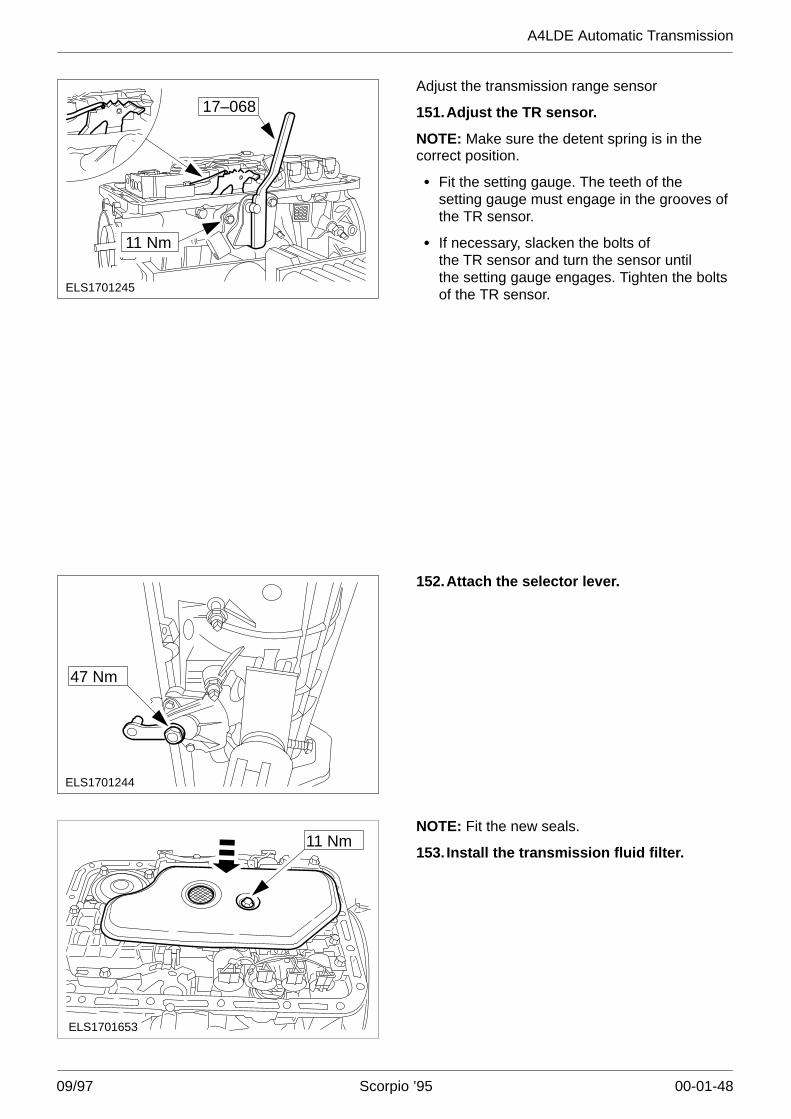
ELS1701245
17–068
11 Nm
Adjust the transmission range sensor
151.Adjust the TR sensor.
NOTE: Make sure the detent spring is in thecorrect position.
� Fit the setting gauge. The teeth of thesetting gauge must engage in the grooves ofthe TR sensor.
� If necessary, slacken the bolts ofthe TR sensor and turn the sensor untilthe setting gauge engages. Tighten the boltsof the TR sensor.
ELS1701244
47 Nm
152.Attach the selector lever.
11 Nm
ELS1701653
NOTE: Fit the new seals.
153. Install the transmission fluid filter.
A4LDE Automatic Transmission
09/97 Scorpio ’95 00-01-49
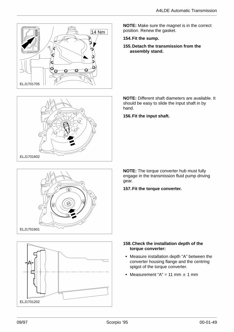
ELJ1701705
14 NmNOTE: Make sure the magnet is in the correctposition. Renew the gasket.
154.Fit the sump.
155.Detach the transmission from theassembly stand.
ELJ1701602
NOTE: Different shaft diameters are available. Itshould be easy to slide the input shaft in byhand.
156.Fit the input shaft.
ELJ1701601
NOTE: The torque converter hub must fullyengage in the transmission fluid pump drivinggear.
157.Fit the torque converter.
A
ELJ1701202
158.Check the installation depth of thetorque converter:
� Measure installation depth “A” between theconverter housing flange and the centringspigot of the torque converter.
� Measurement “A” = 11 mm � 1 mm