Embed Size (px)
Citation preview
3rd Worldwide Aerospace Conference
September, 24-26, 2001
1
MILITARY TRANSPORT AIRCRAFT DIVISION
A340-600 FAN COWLS FINITE ELEMENT MODEL:
USING MSC.Nastran TO MODEL CFC SECONDARY STRUCTURES
WITH CONTACT BOUNDARY CONDITIONS. 2001-43
Sofía Ponce Borrero, Juan Pablo Juste Mencía
Stress Department
Engineering Division
EADS CASA.
Military Transport Aircraft Division
Avda. John Lennon s/n, Getafe, Madrid (Spain)
Tf. +34 91 6242373
e-mail [email protected], [email protected]
ABSTRACT
EADS CASA has large experience in Finite Element Model techniques, making full aircraft
or component models. But since a few years, the modelisation of secondary structures has
taken more importance, up to become an essential part in their analysis, and also because they
are finally integrated into the full component FEM.
The optimisation of the codes and the inclusion of new capabilities in the FEM solvers, in
combination with the increasing in the computer performances have allowed the analysis of
structures under very complex load and boundary conditions using detailed FEMs.
EADS CASA Military Transport Aircraft Division is responsible under AIRCELLE contract
of the design and manufacturing of A340-600 Fan Cowl.
This article describes the process to analyse the A340-600 Fan Cowls using a non-linear
MSC.Nastran solution with contacts and large displacements.
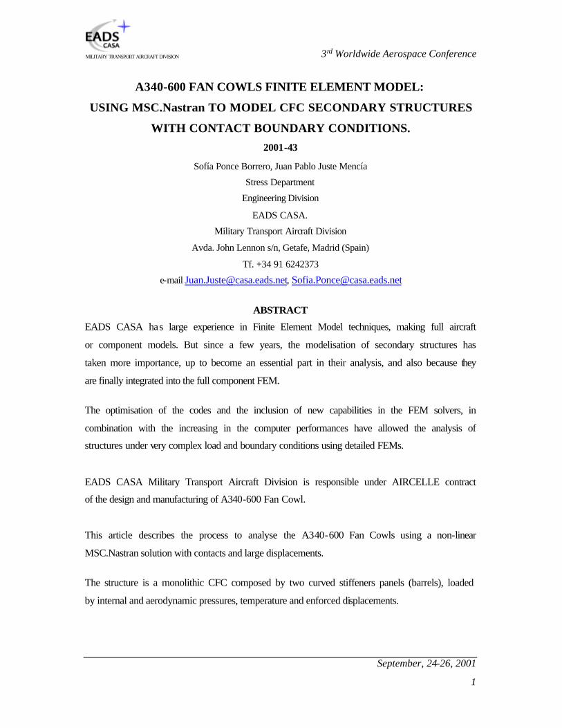
The structure is a monolithic CFC composed by two curved stiffeners panels (barrels), loaded
by internal and aerodynamic pressures, temperature and enforced displacements.

3rd Worldwide Aerospace Conference
September, 24-26, 2001
2
MILITARY TRANSPORT AIRCRAFT DIVISION
The structure is very high affected by the particular supporting and boundaries conditions:
four hinge fittings per side, pretension latches in between and enforced by the displacement of
the rest of the engine devices in the contour.
This method has been successfully used in EADS CASA to obtain stress and strains in CFC
panels and also to predict the correct shape of the tools, due to deformations under
temperature cycles during the manufacturing process.

3rd Worldwide Aerospace Conference
September, 24-26, 2001
3
MILITARY TRANSPORT AIRCRAFT DIVISION
1. Introduction.
EADS CASA is an aircraft manufacturer company that has developed a technological and
productive capacity, which allows it to compete in the international market. It has large
experience in the Finite Element Model techniques in component ones and in
Multidisciplinary Global Aircraft Finite Element Model to be applied to the full aircraft
FEMs.
This article describes the A340-500 TRENT Fan Cowl model and the complexity of its study
due to the special characteristics and requirements involved (non-linear analysis, enforced
displacements, temperature effect, contact elements…). The use of pre-tension loads in order
to fulfil the aerodynamic tolerances and controlling the scooping effect within acceptable
margins is one of the most remarkable features of the Fan Cowl analysis.
The Fan Cowl model herein outlined was built up to allow its integration in the Nacelle
integrated FEM. Improved structural behaviour and more reliability on interface loads are
then achieved.

3rd Worldwide Aerospace Conference
September, 24-26, 2001
4
MILITARY TRANSPORT AIRCRAFT DIVISION
2. Fan Cowl Finite Element Model.
The Fan Cowl Finite Element Model has been generated based on CATIA surfaces in a
directed communication between CATIA and MSC.Patran (CATIA Direct Access). The
monolithic CFC structure composed by two curved stiffeners panels has been modelled using
CQUAD4 and CTRIA3 plate elements. The rest of the model corresponds to the metallic
parts have been simulated by CROD and CBEAM elements. Figure 9.1 represents a general
view.
The model, quite complex due to the high curvature of the surface, includes in addition to the
monolithic CFC structure:
q Four hinges (per side) which represent the interface with the pylon, the landings to
support in the fan case,
q Four latches to assure the perfect closure,
q Two axial locators and a retainer (per side) to restrict the axial and radial displacement
respectively,
q Two Hold Open Rod (per side) when the fan cowl is open for,
q One actuator (per side) to open it.
All of these elements can be seen in figures in point 9.
In order to analyse and show compliance with the Fan Cowls structural requirements, three
different models were necessary to be used:
q The Ground Model used for the study of opening and closing design cases allows the
analysis of each one of the discrete opening angles by rotating of coordinate axis. Linear
Static Solution (SOL 101) has been used for this model. The Hold Open Rods and
Actuator together with the Hinge fittings are the support conditions on this model (Figure
9.5).
q The Flight Model contains non-linear elements like gaps that represent the Inlet and the
Thrust Reverse support and the contact between the two sides of the Fan Cowl. There are
other parts simulated in the flight model as latches, axial locators, retainers that mustn’t
3rd Worldwide Aerospace Conference
September, 24-26, 2001
5
MILITARY TRANSPORT AIRCRAFT DIVISION
work when the Fan Cowl is open. MSC.Nastran’s Non-linear Static Solution (SOL 106)
has been used for the flight model. (Figure 9.1). Large displacements have been
considered to take into account the membrane effect.
q The “Damage Tolerance” model has been created to be able to demonstrate the structure
can withstand large debonding of the stiffener up to limit load. The model consists of a
refined mesh in the critical area for this condition, and the simulation of anti-peeling bolts
by means of CELAS elements between coincident nodes at the stiffener-skin interface.
The required stiffener debonded area is simulated by disconnecting the corresponding
CELAS elements (Figure 9.8).
q Fail safe conditions corresponding to Ground and Flight models have been also
considered.
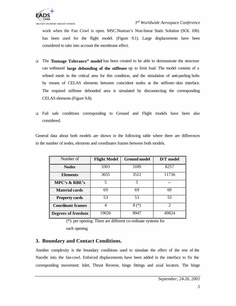
General data about both models are shown in the following table where there are differences
in the number of nodes, elements and coordinates frames between both models.
Number of Flight Model Ground model D/T model
Nodes 3303 3189 8257
Elements 3655 3512 11736
MPC’s & RBE’s 5 5 --
Material cards 69 69 69
Property cards 53 53 53
Coordinate frames 4 8 (*) 2
Degrees of freedom 19026 8947 49824
(*): per opening. There are different co-ordinate systems for
each opening.
3. Boundary and Contact Conditions.
Another complexity is the boundary conditions used to simulate the effect of the rest of the
Nacelle into the fan-cowl. Enforced displacements have been added in the interface to fix the
corresponding movement: Inlet, Thrust Reverse, hinge fittings and axial locators. The hinge
3rd Worldwide Aerospace Conference
September, 24-26, 2001
6
MILITARY TRANSPORT AIRCRAFT DIVISION
fittings have all their degrees of freedom restricted except for the axial displacement that is
only restricted in Inlet and Thrust Reverse.
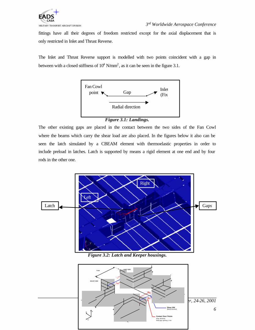
The Inlet and Thrust Reverse support is modelled with two points coincident with a gap in
between with a closed stiffness of 104 N/mm2, as it can be seen in the figure 3.1.
Figure 3.1: Landings.
The other existing gaps are placed in the contact between the two sides of the Fan Cowl
where the beams which carry the shear load are also placed. In the figures below it also can be
seen the latch simulated by a CBEAM element with thermoelastic properties in order to
include preload in latches. Latch is supported by means a rigid element at one end and by four
rods in the other one.
Figure 3.2: Latch and Keeper housings.
Radial direction
• • Inlet (Fix
point)
Fan Cowl point Gap
Latch
Right
Left
Gaps
Shear PIN(Beam Element)
Contact Door Points(Gap Element)Initial gap opening 1 mm
X
Y
Z
RIGHT SIDE
LEFT SIDE1 mm

3rd Worldwide Aerospace Conference
September, 24-26, 2001
7
MILITARY TRANSPORT AIRCRAFT DIVISION
Figure 3.3: Gaps in latches.
The axial locator modelisation is also simulated by two coincident nodes attached in
longitudinal direction with stiffness in open and closed condition.
Figure 3.3: Axial locator
The retainer is also performed giving stiffness to correspond CGAP element when is open and
closed but in radial direction.
Figure 3.4:Radial retainer.
4. Loads.
Several flight cases as well as ground ones have been covered with the complete Fan Cowl
analysis.
Flight Load cases:
This type of cases is composed by several loads:
q External Cp (aerodynamic coefficient of pressure) values are provided and taken as
basis to simulate the pressure with PLOAD4 cards.
q Internal pressure is also taken into account by means of PLOAD4 cards.
q The fan cowl weight is included through a GRAV card.
q The temperature effect has been considered in the material properties and some higher
temperatures have been used in the analysis of the duct burst event.
Axial direction
• • Inlet (Fix
point)
Fan Cowl point Gap
Radial direction
• • Inlet (Fix
point)
Fan Cowl point Gap

3rd Worldwide Aerospace Conference
September, 24-26, 2001
8
MILITARY TRANSPORT AIRCRAFT DIVISION
q Pretension load in the latches. This pretension load is simulated by nodal temperature
cards applied in the extremes of the latch, represented by a beam. Therefore TEMPD cards
have been added
q Enforced displacements coming from the Nacelle integrated FEM. They simulate the
interface with the fan case and the joint to the pylon, which have a very high influence in
the interface loads.
A significant effect studied is the scooping. It must be considered an additional internal
pressure in those cases in which displacements in the Inlet area are higher than the
thickness, due to the air stream is allowed to come into the fan cowl. This effect is included
in the loads analysed.
Ground Load cases:
The ground cases analysed are taking into account the different fan cowl openings up to 55
grades. The values for Actuator and Hold Open Rod loads, obtained for 45 Knots cases
supported on actuator and 60 Knots cases supported on Hold Open Rod, depend so much
on the fan cowl opening.
Different boundary conditions combinations are studied for the different openings due to a
few conditions of HOR and Actuator support. In one of the intermediate apertures, 38º the
HOR are blocked and they are assumed not to go down from this opening. This effect has
been considered supposing the HOR only withstand tension loads and not compression.
With 55 º the Fan Cowl is only supported in HOR and not in Actuator.
When the Fan Cowl is open it is not supported in the Inlet and Thrust Reverse, therefore
there aren’t enforced displacements in the analysis. However the Hold Open Rod and the
actuator are supported on the engine.
All these points are necessary to take into account all the requirements that must fulfil the Fan
Cowl, and they make its analysis quite complex and time consuming. 82 static cases, 30
fatigue cases, 121 fail safe cases and 2200 ground cases have been considered. It has been
necessary to create automatic procedures to be able to study all these cases, methods that read

3rd Worldwide Aerospace Conference
September, 24-26, 2001
9
MILITARY TRANSPORT AIRCRAFT DIVISION
the MSC.Nastran output files. With these results it has been obtained the interface loads,
strains and stress values in skin and stiffeners, displacements in Inlet and Thrust Reverse, …
5. Analysis.
The different models are analysed in different ways:
q For all the flight cases, non-linear analysis has been studied because there are non-linear
elements as the gaps that simulate the supports in Inlet and Thrust Reverse and the contact
between both sides in the latch area.
As it is a non-linear analysis there are quite important parameters used in the NLPARM
card to assure the solution convergence.
NLPARM card Default Used
NINC 10 25
KMETHOD AUTO SEMI
KSTEP 5
MAXITER 25
CONV PW
INTOUT NO
EPSU 0.01
EPSP 1.0E-3 0.01
EPSW 1.0E-7
1.0E-5 1.0E-6
q In the ground cases these elements do not appear because the fan cowl is open, therefore
it can be used a linear solution (SOL 101) to analyse the results. A non-linear solution is
not necessary because the most important effect is bending and not membrane one, and
because there aren’t gaps.
q The “Damage Tolerance” model study has been performed using a buckling solution
(SOL 105).
Some results for the three models are shown in figures 9.6-9.8.
The parameters in the case control statement are the following:

3rd Worldwide Aerospace Conference
September, 24-26, 2001
10
MILITARY TRANSPORT AIRCRAFT DIVISION
- LGDISP=1: Large displacement effects (updated element co-ordinates and follower
forces).
- AUTOSPC=NO: The singularities are not constrained.
- K6ROT=100: It’s a high value to be able to suppress the grid point singularities.
Another analyses performed with the Fan Cowl model are Engine Imbalance and
environmental dynamic analysis. These dynamic analyses have the particularity to combine a
non-linear FEM structural model with input loads that are given in terms of vibration spectra
(which in turn implies linear calculation). The first work consists of studying linearised
conditions approach and then develops the methodology and application to the Fan Cowls
considering non-linear conditions. The second one starts with the linearisation of boundary
conditions and goes on with the application of the vibration envelope spectrum to the Fan
Cowl. Figures 9.9 and 9.10 show different responses.
6. Quality Assurance.
A full static and dynamic quality assurance has been performed with the Fan Cowl model to
assure a quality level giving good static and dynamic responses following EADS CASA
procedures.
The geometrical checks, performed using the MSC.Nastran V68.2.3 with solution 101 and
with MSC.Patran V8.0, are the following: coincident nodes only in boundaries between the
Fan-Cowl and the nacelle, and in the door area; coincident elements connecting coincident
nodes in door area; free edges, element warping, interior angles, ELAS and GAP elements,
rigid elements, co-ordinate systems, connectivity and element co-ordinates, material co-
ordinate systems…
In the static validation the model is loaded with a test load case in order to check the general
model performances.
The results of the static checks show there are only reactions where the model is supported,
the MPC forces in latches are in the right direction, the applied load resultant is equal to the
reaction forces resultant, maximum ratio, epsilon and external work are under limit values,…

3rd Worldwide Aerospace Conference
September, 24-26, 2001
11
MILITARY TRANSPORT AIRCRAFT DIVISION
In the dynamic validation the structure is free without interface with the nacelle. Seven
different runs have been performed using different values for PARAM and SPC.
7. Future Improvements.
A possible improvement that can be developed in the future is the use of Superelements to
replace the enforced displacements nowadays applied. With the use of imported stiffness
matrix to simulate the rest of the structure the results accuracy would be improved.
8. Conclusions.
The analysis performed by EADS CASA for the Fan Cowl study has demonstrated that the
modelisation of secondary structures is an essential work to reproduce the real behaviour of
the structure with a high precision, integrating it then in a full component model.
The boundary conditions complexity simulating the contact with the rest of the nacelle, the
non-linear solutions analysed, the amount of load cases studied let us reproduce the real
behaviour of the structure with more accuracy taking into account all the possible situations in
flight and in ground.

3rd Worldwide Aerospace Conference
September, 24-26, 2001
12
MILITARY TRANSPORT AIRCRAFT DIVISION
9. Figures.
Figure 9.1.- General Fan Cowl view.
FWD
RWD

3rd Worldwide Aerospace Conference
September, 24-26, 2001
13
MILITARY TRANSPORT AIRCRAFT DIVISION
Figure 9.2.-: Hinge fitting view.
Figure 9.3. Locator and retainer positions.
Figure 9.4. Landing positions.
Lower right locator
Lower left locator Retainers
Thrust reverse
landings
Inlet
landings

3rd Worldwide Aerospace Conference
September, 24-26, 2001
14
MILITARY TRANSPORT AIRCRAFT DIVISION
Figure 9.5.- Fan Cowl open.
Figure 9.6.- Duct burst case displacements.
Actuators
Hold Open
Rods

3rd Worldwide Aerospace Conference
September, 24-26, 2001
15
MILITARY TRANSPORT AIRCRAFT DIVISION
Figure 9.7. Displacements
Figure 9.8.- Stiffener disbonding.

3rd Worldwide Aerospace Conference
September, 24-26, 2001
16
MILITARY TRANSPORT AIRCRAFT DIVISION
Figure 9.9. A340-500/600 fan cowl normal mode: Local first upper fitting mode (89.08 Hz).
Figure 9.10. A340-500/600 fan cowl normal mode: Local rear latch mode (93.40 Hz).