Embed Size (px)
Citation preview
A3
A3
A3
A3
A3
A3
A3
A3
A3
A3
A3
A3
A3
A3
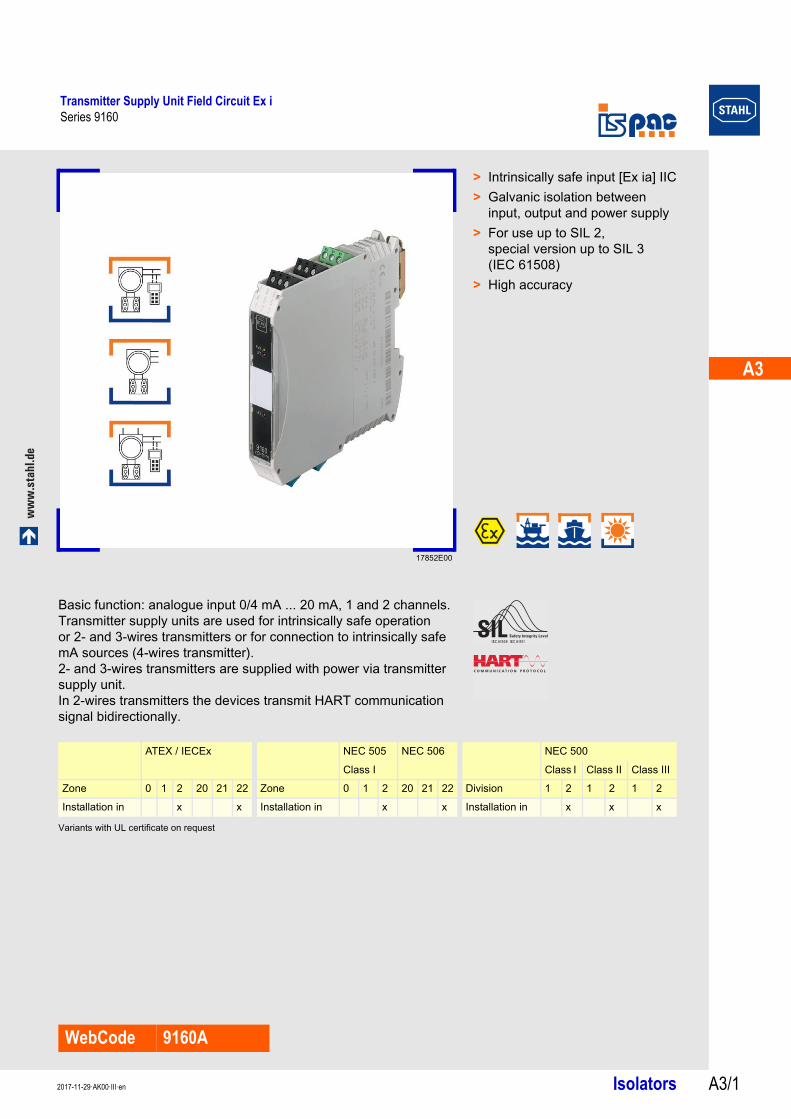
Transmitter Supply Unit Field Circuit Ex iSeries 9160
ww
w.s
tah
l.d
e
Isolators A3/12017-11-29·AK00·III·en
Series 9160 A3
17852E00
WebCode 9160A
> Intrinsically safe input [Ex ia] IIC
> Galvanic isolation between input, output and power supply
> For use up to SIL 2, special version up to SIL 3 (IEC 61508)
> High accuracy
Basic function: analogue input 0/4 mA ... 20 mA, 1 and 2 channels.Transmitter supply units are used for intrinsically safe operation or 2- and 3-wires transmitters or for connection to intrinsically safe mA sources (4-wires transmitter).2- and 3-wires transmitters are supplied with power via transmitter supply unit.In 2-wires transmitters the devices transmit HART communication signal bidirectionally.
Variants with UL certificate on request
ATEX / IECEx NEC 505 NEC 506 NEC 500
Class I Class I Class II Class III
Zone 0 1 2 20 21 22 Zone 0 1 2 20 21 22 Division 1 2 1 2 1 2
Installation in x x Installation in x x Installation in x x x
Transmitter Supply Unit Field Circuit Ex iSeries 9160
Isolators 2017-11-29·AK00·III·enA3/2
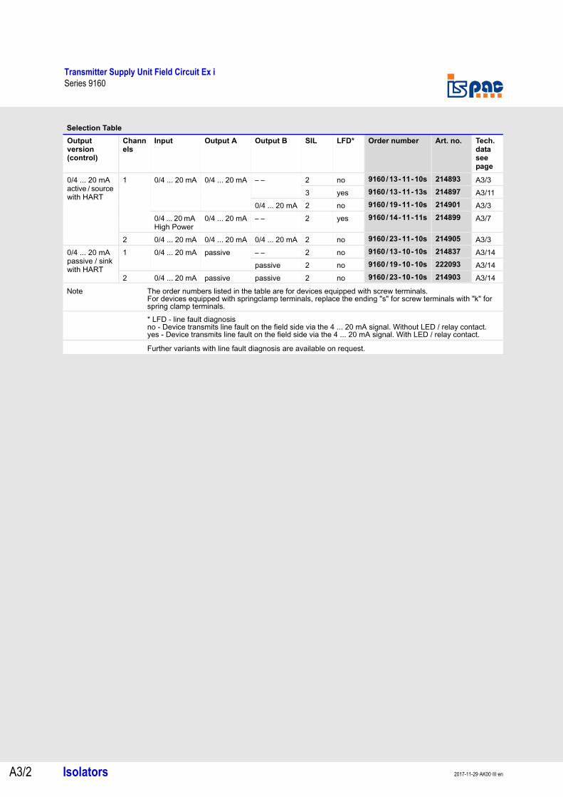
Selection Table
Output version (control)
Channels
Input Output A Output B SIL LFD* Order number Art. no. Tech. data see page
0/4 ... 20 mA active / source with HART
1 0/4 ... 20 mA 0/4 ... 20 mA – – 2 no 9160/13-11-10s 214893 A3/3
3 yes 9160/13-11-13s 214897 A3/11
0/4 ... 20 mA 2 no 9160/19-11-10s 214901 A3/3
0/4 ... 20 mA High Power
0/4 ... 20 mA – – 2 yes 9160/14-11-11s 214899 A3/7
2 0/4 ... 20 mA 0/4 ... 20 mA 0/4 ... 20 mA 2 no 9160/23-11-10s 214905 A3/3
0/4 ... 20 mA passive / sink with HART
1 0/4 ... 20 mA passive – – 2 no 9160/13-10-10s 214837 A3/14
passive 2 no 9160/19-10-10s 222093 A3/14
2 0/4 ... 20 mA passive passive 2 no 9160/23-10-10s 214903 A3/14
Note The order numbers listed in the table are for devices equipped with screw terminals.For devices equipped with springclamp terminals, replace the ending "s" for screw terminals with "k" for spring clamp terminals.* LFD - line fault diagnosisno - Device transmits line fault on the field side via the 4 ... 20 mA signal. Without LED / relay contact.yes - Device transmits line fault on the field side via the 4 ... 20 mA signal. With LED / relay contact.
Further variants with line fault diagnosis are available on request.
A3
A3
A3
A3
A3
A3
A3
A3
A3
A3
A3
A3
A3
A3
Transmitter Supply Unit Field Circuit Ex iSeries 9160/xx-11-10
Isolators A3/32017-11-29·AK00·III·en
Series 9160/xx-11-10
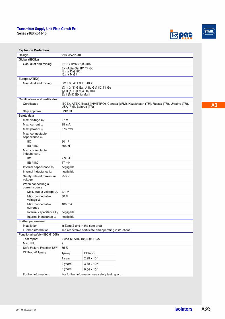
Explosion Protection
Design 9160/xx-11-10Global (IECEx)
Gas, dust and mining IECEx BVS 08.0050XEx nA [ia Ga] IIC T4 Gc[Ex ia Da] IIIC[Ex ia Ma] I
Europe (ATEX)Gas, dust and mining DMT 03 ATEX E 010 X
E II 3 (1) G Ex nA [ia Ga] IIC T4 GcE II (1) D [Ex ia Da] IIICE I (M1) [Ex ia Ma] I
Certifications and certificatesCertificates IECEx, ATEX, Brasil (INMETRO), Canada (cFM), Kazakhstan (TR), Russia (TR), Ukraine (TR),
USA (FM), Belarus (TR)Ship approval DNV GL
Safety dataMax. voltage Uo 27 V Max. current Io 88 mA Max. power Po 576 mW Max. connectable capacitance Co
IIC 90 nFIIB / IIIC 705 nF
Max. connectable inductance Lo
IIC 2.3 mHIIB / IIIC 17 mH
Internal capacitance Ci negligibleInternal inductance Li negligibleSafety-related maximum voltage
253 V
When connecting a current source
Max. output voltage Uo 4.1 V Max. connectable voltage Ui
30 V
Max. connectable current Ii
100 mA
Internal capacitance Ci negligibleInternal inductance Li negligible
Further parametersInstallation in Zone 2 and in the safe areaFurther information see respective certificate and operating instructions
Functional safety (IEC 61508)Test report Exida STAHL 10/02-01 R027Max. SIL 2Safe Failure Fraction SFF 85 %PFDAVG at T[Proof]
Further information For further information see safety test report.
T[Proof] PFDAVG
1 year 2.29 x 10⁻⁴
2 years 3.38 x 10⁻⁴
5 years 6.64 x 10⁻⁴
Transmitter Supply Unit Field Circuit Ex iSeries 9160/xx-11-10
Isolators 2017-11-29·AK00·III·enA3/4
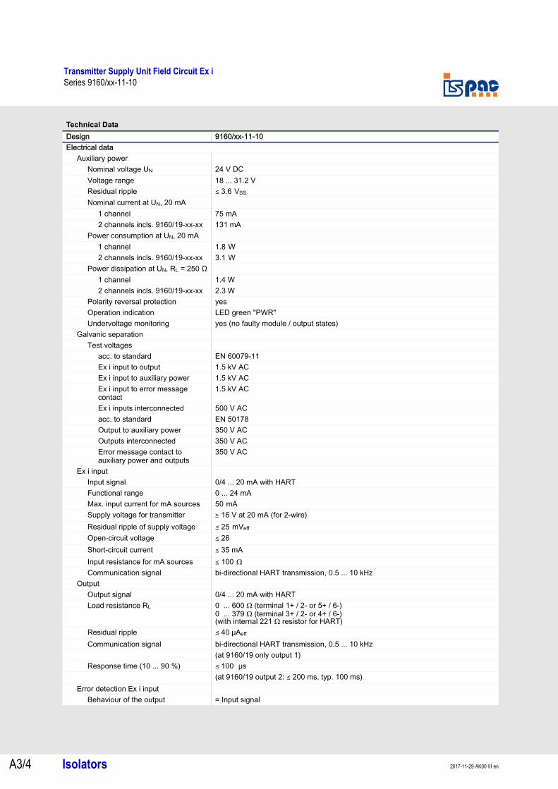
Technical Data
Design 9160/xx-11-10Electrical data
Auxiliary powerNominal voltage UN 24 V DCVoltage range 18 ... 31.2 VResidual ripple ( 3.6 VSS Nominal current at UN, 20 mA
1 channel 75 mA2 channels incls. 9160/19-xx-xx 131 mA
Power consumption at UN, 20 mA1 channel 1.8 W 2 channels incls. 9160/19-xx-xx 3.1 W
Power dissipation at UN, RL = 250 Ω1 channel 1.4 W2 channels incls. 9160/19-xx-xx 2.3 W
Polarity reversal protection yesOperation indication LED green "PWR"Undervoltage monitoring yes (no faulty module / output states)
Galvanic separationTest voltages
acc. to standard EN 60079-11Ex i input to output 1.5 kV ACEx i input to auxiliary power 1.5 kV ACEx i input to error message contact
1.5 kV AC
Ex i inputs interconnected 500 V ACacc. to standard EN 50178Output to auxiliary power 350 V ACOutputs interconnected 350 V ACError message contact to auxiliary power and outputs
350 V AC
Ex i inputInput signal 0/4 ... 20 mA with HARTFunctional range 0 ... 24 mAMax. input current for mA sources 50 mA Supply voltage for transmitter ) 16 V at 20 mA (for 2-wire)Residual ripple of supply voltage ( 25 mVeff Open-circuit voltage ( 26Short-circuit current ( 35 mAInput resistance for mA sources ( 100 Ω Communication signal bi-directional HART transmission, 0.5 ... 10 kHz
OutputOutput signal 0/4 ... 20 mA with HARTLoad resistance RL 0 ... 600 Ω (terminal 1+ / 2- or 5+ / 6-)
0 ... 379 Ω (terminal 3+ / 2- or 4+ / 6-)(with internal 221 Ω resistor for HART)
Residual ripple ( 40 μAeff
Communication signal bi-directional HART transmission, 0.5 ... 10 kHz(at 9160/19 only output 1)
Response time (10 ... 90 %) ( 100 μs (at 9160/19 output 2: ( 200 ms, typ. 100 ms)
Error detection Ex i inputBehaviour of the output = Input signal
A3
A3
A3
A3
A3
A3
A3
A3
A3
A3
A3
A3
A3
A3
Transmitter Supply Unit Field Circuit Ex iSeries 9160/xx-11-10
Isolators A3/52017-11-29·AK00·III·en
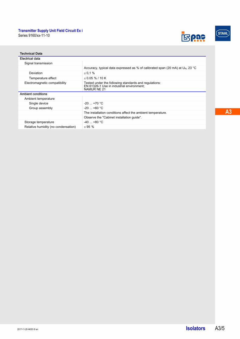
Electrical dataSignal transmission
Accuracy, typical data expressed as % of calibrated span (20 mA) at UN, 23 °CDeviation ( 0,1 %Temperature effect ( 0.05 % / 10 K
Electromagnetic compatibility Tested under the following standards and regulations: EN 61326-1 Use in industrial environment; NAMUR NE 21
Ambient conditionsAmbient temperature
Single device -20 ... +70 °CGroup assembly -20 ... +60 °C
The installation conditions affect the ambient temperature.Observe the "Cabinet installation guide".
Storage temperature -40 ... +80 °C Relative humidity (no condensation) ( 95 %
Technical Data
Transmitter Supply Unit Field Circuit Ex iSeries 9160/xx-11-10
Isolators 2017-11-29·AK00·III·enA3/6
Technical Data
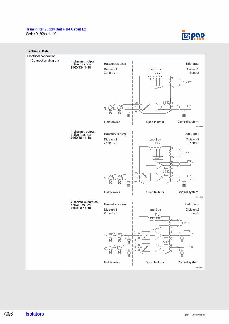
Electrical connectionConnection diagram 1 channel, output:
active / source9160/13-11-10.
14163E02
1 channel, output: active / source9160/19-11-10.
14164E02
2 channels, outputs: active / source9160/23-11-10.
14165E02
Hazardous area Safe area
Field device ISpac Isolator Control system
Division 1Zone 0 / 1
Division 2Zone 2
pac Bus-
Hazardous area Safe area
Field device ISpac Isolator Control system
Division 1Zone 0 / 1
Division 2Zone 2
pac Bus-
Hazardous area Safe area
Field device ISpac Isolator Control system
Division 1Zone 0 / 1
Division 2Zone 2
pac Bus-
A3
A3
A3
A3
A3
A3
A3
A3
A3
A3
A3
A3
A3
A3
Transmitter Supply Unit Field Circuit Ex iSeries 9160/xx-11-11
Isolators A3/72017-11-29·AK00·III·en
Series 9160/xx-11-11
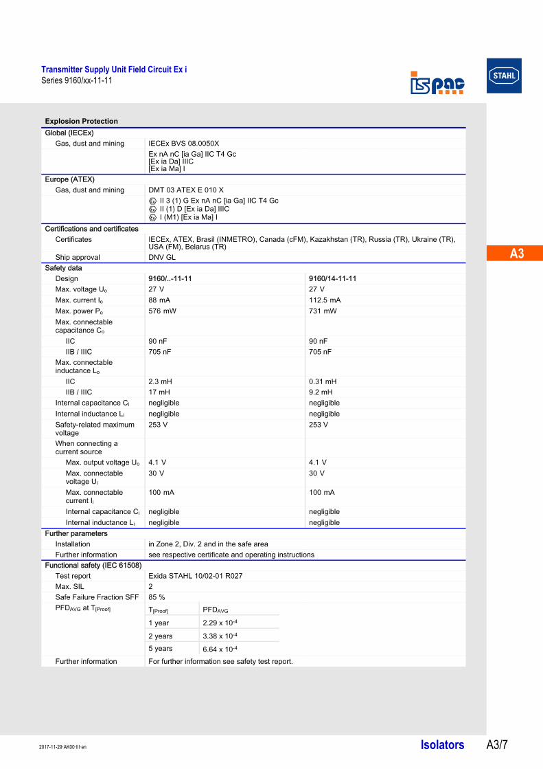
Explosion Protection
Global (IECEx)Gas, dust and mining IECEx BVS 08.0050X
Ex nA nC [ia Ga] IIC T4 Gc[Ex ia Da] IIIC[Ex ia Ma] I
Europe (ATEX)Gas, dust and mining DMT 03 ATEX E 010 X
E II 3 (1) G Ex nA nC [ia Ga] IIC T4 GcE II (1) D [Ex ia Da] IIICE I (M1) [Ex ia Ma] I
Certifications and certificatesCertificates IECEx, ATEX, Brasil (INMETRO), Canada (cFM), Kazakhstan (TR), Russia (TR), Ukraine (TR),
USA (FM), Belarus (TR)Ship approval DNV GL
Safety dataDesign 9160/..-11-11 9160/14-11-11Max. voltage Uo 27 V 27 V Max. current Io 88 mA 112.5 mA Max. power Po 576 mW 731 mW Max. connectable capacitance Co
IIC 90 nF 90 nFIIB / IIIC 705 nF 705 nF
Max. connectable inductance Lo
IIC 2.3 mH 0.31 mHIIB / IIIC 17 mH 9.2 mH
Internal capacitance Ci negligible negligibleInternal inductance Li negligible negligibleSafety-related maximum voltage
253 V 253 V
When connecting a current source
Max. output voltage Uo 4.1 V 4.1 V Max. connectable voltage Ui
30 V 30 V
Max. connectable current Ii
100 mA 100 mA
Internal capacitance Ci negligible negligibleInternal inductance Li negligible negligible
Further parametersInstallation in Zone 2, Div. 2 and in the safe areaFurther information see respective certificate and operating instructions
Functional safety (IEC 61508)Test report Exida STAHL 10/02-01 R027Max. SIL 2Safe Failure Fraction SFF 85 %PFDAVG at T[Proof]
Further information For further information see safety test report.
T[Proof] PFDAVG
1 year 2.29 x 10⁻⁴
2 years 3.38 x 10⁻⁴
5 years 6.64 x 10⁻⁴
Transmitter Supply Unit Field Circuit Ex iSeries 9160/xx-11-11
Isolators 2017-11-29·AK00·III·enA3/8
Technical Data
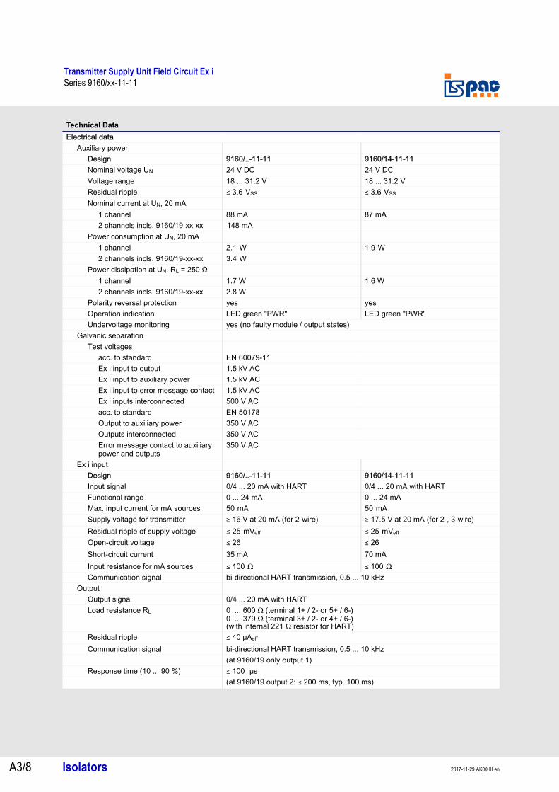
Electrical dataAuxiliary power
Design 9160/..-11-11 9160/14-11-11Nominal voltage UN 24 V DC 24 V DCVoltage range 18 ... 31.2 V 18 ... 31.2 VResidual ripple ( 3.6 VSS ( 3.6 VSS Nominal current at UN, 20 mA
1 channel 88 mA 87 mA2 channels incls. 9160/19-xx-xx 148 mA
Power consumption at UN, 20 mA1 channel 2.1 W 1.9 W 2 channels incls. 9160/19-xx-xx 3.4 W
Power dissipation at UN, RL = 250 Ω1 channel 1.7 W 1.6 W 2 channels incls. 9160/19-xx-xx 2.8 W
Polarity reversal protection yes yesOperation indication LED green "PWR" LED green "PWR"Undervoltage monitoring yes (no faulty module / output states)
Galvanic separationTest voltages
acc. to standard EN 60079-11Ex i input to output 1.5 kV ACEx i input to auxiliary power 1.5 kV ACEx i input to error message contact 1.5 kV ACEx i inputs interconnected 500 V ACacc. to standard EN 50178Output to auxiliary power 350 V ACOutputs interconnected 350 V ACError message contact to auxiliary power and outputs
350 V AC
Ex i inputDesign 9160/..-11-11 9160/14-11-11Input signal 0/4 ... 20 mA with HART 0/4 ... 20 mA with HARTFunctional range 0 ... 24 mA 0 ... 24 mAMax. input current for mA sources 50 mA 50 mA Supply voltage for transmitter ) 16 V at 20 mA (for 2-wire) ) 17.5 V at 20 mA (for 2-, 3-wire)Residual ripple of supply voltage ( 25 mVeff ( 25 mVeff Open-circuit voltage ( 26 ( 26Short-circuit current 35 mA 70 mAInput resistance for mA sources ( 100 Ω ( 100 Ω Communication signal bi-directional HART transmission, 0.5 ... 10 kHz
OutputOutput signal 0/4 ... 20 mA with HARTLoad resistance RL 0 ... 600 Ω (terminal 1+ / 2- or 5+ / 6-)
0 ... 379 Ω (terminal 3+ / 2- or 4+ / 6-)(with internal 221 Ω resistor for HART)
Residual ripple ( 40 μAeff
Communication signal bi-directional HART transmission, 0.5 ... 10 kHz(at 9160/19 only output 1)
Response time (10 ... 90 %) ( 100 μs (at 9160/19 output 2: ( 200 ms, typ. 100 ms)
A3
A3
A3
A3
A3
A3
A3
A3
A3
A3
A3
A3
A3
A3
Transmitter Supply Unit Field Circuit Ex iSeries 9160/xx-11-11
Isolators A3/92017-11-29·AK00·III·en
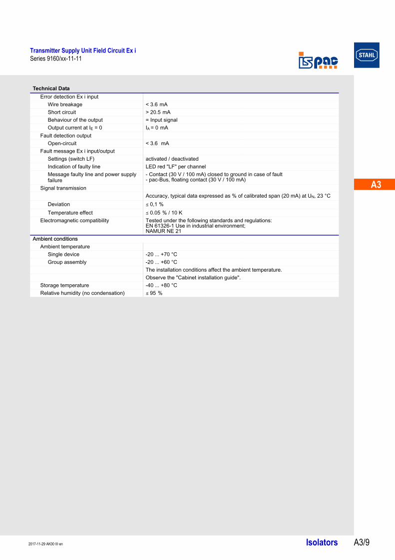
Error detection Ex i inputWire breakage < 3.6 mA Short circuit > 20.5 mA Behaviour of the output = Input signalOutput current at IE = 0 IA = 0 mA
Fault detection outputOpen-circuit < 3.6 mA
Fault message Ex i input/outputSettings (switch LF) activated / deactivatedIndication of faulty line LED red "LF" per channelMessage faulty line and power supply failure
- Contact (30 V / 100 mA) closed to ground in case of fault- pac-Bus, floating contact (30 V / 100 mA)
Signal transmissionAccuracy, typical data expressed as % of calibrated span (20 mA) at UN, 23 °C
Deviation ( 0,1 %Temperature effect ( 0.05 % / 10 K
Electromagnetic compatibility Tested under the following standards and regulations: EN 61326-1 Use in industrial environment; NAMUR NE 21
Ambient conditionsAmbient temperature
Single device -20 ... +70 °CGroup assembly -20 ... +60 °C
The installation conditions affect the ambient temperature.Observe the "Cabinet installation guide".
Storage temperature -40 ... +80 °C Relative humidity (no condensation) ( 95 %
Technical Data
Transmitter Supply Unit Field Circuit Ex iSeries 9160/xx-11-11
Isolators 2017-11-29·AK00·III·enA3/10
Technical Data
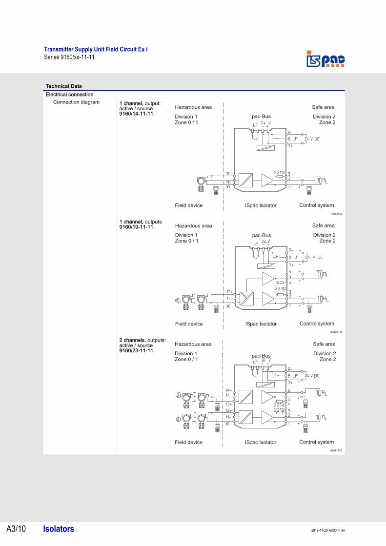
Electrical connectionConnection diagram 1 channel, output:
active / source9160/14-11-11.
11563E02
1 channel, outputs9160/19-11-11.
06675E02
2 channels, outputs: active / source9160/23-11-11.
06471E02
Hazardous area Safe area
Field device ISpac Isolator Control system
Division 1Zone 0 / 1
Division 2Zone 2
pac-Bus
Hazardous area Safe area
Field device ISpac Isolator Control system
Division 1Zone 0 / 1
Division 2Zone 2
pac Bus-
Hazardous area Safe area
Division 1Zone 0 / 1
Division 2Zone 2
pac-Bus
Field device ISpac Isolator Control system
A3
A3
A3
A3
A3
A3
A3
A3
A3
A3
A3
A3
A3
A3
Transmitter Supply Unit Field Circuit Ex iSeries 9160/13-11-13
Isolators A3/112017-11-29·AK00·III·en
Series 9160/13-11-13
Explosion Protection
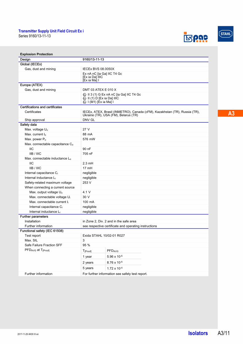
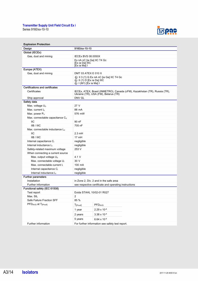
Design 9160/13-11-13Global (IECEx)
Gas, dust and mining IECEx BVS 08.0050XEx nA nC [ia Ga] IIC T4 Gc[Ex ia Da] IIIC[Ex ia Ma] I
Europe (ATEX)Gas, dust and mining DMT 03 ATEX E 010 X
E II 3 (1) G Ex nA nC [ia Ga] IIC T4 GcE II (1) D [Ex ia Da] IIICE I (M1) [Ex ia Ma] I
Certifications and certificatesCertificates IECEx, ATEX, Brasil (INMETRO), Canada (cFM), Kazakhstan (TR), Russia (TR),
Ukraine (TR), USA (FM), Belarus (TR)Ship approval DNV GL
Safety dataMax. voltage Uo 27 V Max. current Io 88 mA Max. power Po 576 mW Max. connectable capacitance Co
IIC 90 nFIIB / IIIC 705 nF
Max. connectable inductance Lo
IIC 2.3 mHIIB / IIIC 17 mH
Internal capacitance Ci negligibleInternal inductance Li negligibleSafety-related maximum voltage 253 VWhen connecting a current source
Max. output voltage Uo 4.1 V Max. connectable voltage Ui 30 V Max. connectable current Ii 100 mA Internal capacitance Ci negligibleInternal inductance Li negligible
Further parametersInstallation in Zone 2, Div. 2 and in the safe areaFurther information see respective certificate and operating instructions
Functional safety (IEC 61508)Test report Exida STAHL 10/02-01 R027Max. SIL 3Safe Failure Fraction SFF 95 %PFDAVG at T[Proof]
Further information For further information see safety test report.
T[Proof] PFDAVG
1 year 5.96 x 10⁻⁵
2 years 8.76 x 10⁻⁵
5 years 1.72 x 10⁻⁴
Transmitter Supply Unit Field Circuit Ex iSeries 9160/13-11-13
Isolators 2017-11-29·AK00·III·enA3/12
Technical Data
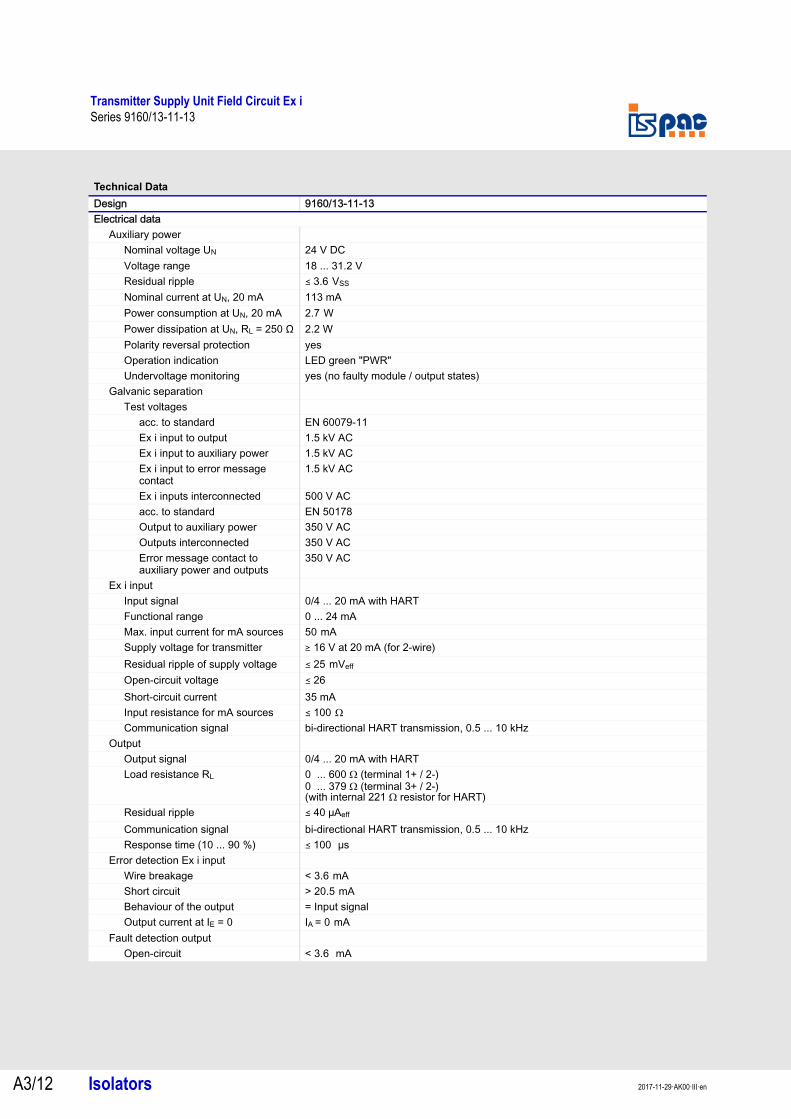
Design 9160/13-11-13Electrical data
Auxiliary powerNominal voltage UN 24 V DCVoltage range 18 ... 31.2 VResidual ripple ( 3.6 VSS Nominal current at UN, 20 mA 113 mAPower consumption at UN, 20 mA 2.7 W Power dissipation at UN, RL = 250 Ω 2.2 WPolarity reversal protection yesOperation indication LED green "PWR"Undervoltage monitoring yes (no faulty module / output states)
Galvanic separationTest voltages
acc. to standard EN 60079-11Ex i input to output 1.5 kV ACEx i input to auxiliary power 1.5 kV ACEx i input to error message contact
1.5 kV AC
Ex i inputs interconnected 500 V ACacc. to standard EN 50178Output to auxiliary power 350 V ACOutputs interconnected 350 V ACError message contact to auxiliary power and outputs
350 V AC
Ex i inputInput signal 0/4 ... 20 mA with HARTFunctional range 0 ... 24 mAMax. input current for mA sources 50 mA Supply voltage for transmitter ) 16 V at 20 mA (for 2-wire)Residual ripple of supply voltage ( 25 mVeff Open-circuit voltage ( 26Short-circuit current 35 mAInput resistance for mA sources ( 100 Ω Communication signal bi-directional HART transmission, 0.5 ... 10 kHz
OutputOutput signal 0/4 ... 20 mA with HARTLoad resistance RL 0 ... 600 Ω (terminal 1+ / 2-)
0 ... 379 Ω (terminal 3+ / 2-)(with internal 221 Ω resistor for HART)
Residual ripple ( 40 μAeff
Communication signal bi-directional HART transmission, 0.5 ... 10 kHzResponse time (10 ... 90 %) ( 100 μs
Error detection Ex i inputWire breakage < 3.6 mA Short circuit > 20.5 mA Behaviour of the output = Input signalOutput current at IE = 0 IA = 0 mA
Fault detection outputOpen-circuit < 3.6 mA
A3
A3
A3
A3
A3
A3
A3
A3
A3
A3
A3
A3
A3
A3
Transmitter Supply Unit Field Circuit Ex iSeries 9160/13-11-13
Isolators A3/132017-11-29·AK00·III·en
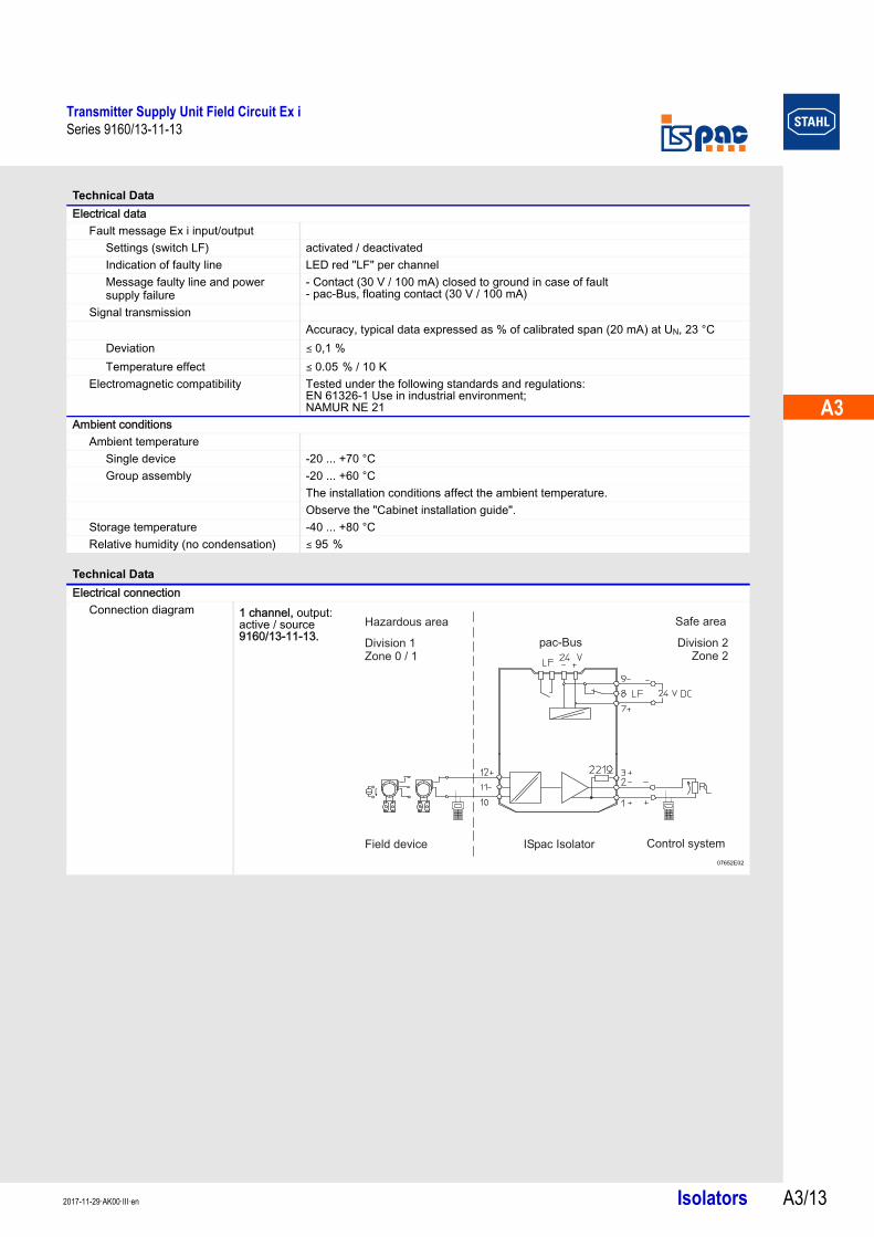
Electrical dataFault message Ex i input/output
Settings (switch LF) activated / deactivatedIndication of faulty line LED red "LF" per channelMessage faulty line and power supply failure
- Contact (30 V / 100 mA) closed to ground in case of fault- pac-Bus, floating contact (30 V / 100 mA)
Signal transmissionAccuracy, typical data expressed as % of calibrated span (20 mA) at UN, 23 °C
Deviation ( 0,1 %Temperature effect ( 0.05 % / 10 K
Electromagnetic compatibility Tested under the following standards and regulations: EN 61326-1 Use in industrial environment; NAMUR NE 21
Ambient conditionsAmbient temperature
Single device -20 ... +70 °CGroup assembly -20 ... +60 °C
The installation conditions affect the ambient temperature.Observe the "Cabinet installation guide".
Storage temperature -40 ... +80 °C Relative humidity (no condensation) ( 95 %
Technical Data
Electrical connectionConnection diagram
Technical Data
1 channel, output: active / source9160/13-11-13.
07652E02
Hazardous area Safe area
Field device ISpac Isolator Control system
Division 1Zone 0 / 1
Division 2Zone 2
pac-Bus
Transmitter Supply Unit Field Circuit Ex iSeries 9160/xx-10-10
Isolators 2017-11-29·AK00·III·enA3/14
Series 9160/xx-10-10
Explosion Protection
Design 9160/xx-10-10Global (IECEx)
Gas, dust and mining IECEx BVS 08.0050XEx nA nC [ia Ga] IIC T4 Gc[Ex ia Da] IIIC[Ex ia Ma] I
Europe (ATEX)Gas, dust and mining DMT 03 ATEX E 010 X
E II 3 (1) G Ex nA nC [ia Ga] IIC T4 GcE II (1) D [Ex ia Da] IIICE I (M1) [Ex ia Ma] I
Certifications and certificatesCertificates IECEx, ATEX, Brasil (INMETRO), Canada (cFM), Kazakhstan (TR), Russia (TR),
Ukraine (TR), USA (FM), Belarus (TR)Ship approval DNV GL
Safety dataMax. voltage Uo 27 V Max. current Io 88 mA Max. power Po 576 mW Max. connectable capacitance Co
IIC 90 nFIIB / IIIC 705 nF
Max. connectable inductance Lo
IIC 2.3 mHIIB / IIIC 17 mH
Internal capacitance Ci negligibleInternal inductance Li negligibleSafety-related maximum voltage 253 VWhen connecting a current source
Max. output voltage Uo 4.1 V Max. connectable voltage Ui 30 V Max. connectable current Ii 100 mA Internal capacitance Ci negligibleInternal inductance Li negligible
Further parametersInstallation in Zone 2, Div. 2 and in the safe areaFurther information see respective certificate and operating instructions
Functional safety (IEC 61508)Test report Exida STAHL 10/02-01 R027Max. SIL 2Safe Failure Fraction SFF 85 %PFDAVG at T[Proof]
Further information For further information see safety test report.
T[Proof] PFDAVG
1 year 2.29 x 10⁻⁴
2 years 3.38 x 10⁻⁴
5 years 6.64 x 10⁻⁴

A3
A3
A3
A3
A3
A3
A3
A3
A3
A3
A3
A3
A3
A3
Transmitter Supply Unit Field Circuit Ex iSeries 9160/xx-10-10
Isolators A3/152017-11-29·AK00·III·en
Technical Data
Design 9160/xx-10-10Electrical data
Auxiliary powerNominal voltage UN 24 V DCVoltage range 18 ... 31.2 VResidual ripple ( 3.6 VSS Nominal current at UN, 20 mA
1 channel 57 mA2 channels 100 mA
Power consumption at UN, 20 mA1 channel 1.4 W 2 channels 2.3 W
Power dissipation at UN, RL = 250 Ω1 channel 1.1 W2 channels 1.7 W
Polarity reversal protection yesOperation indication LED green "PWR"Undervoltage monitoring yes (no faulty module / output states)
Galvanic separationTest voltages
acc. to standard EN 60079-11Ex i input to output 1.5 kV ACEx i input to auxiliary power 1.5 kV ACEx i input to error message contact
1.5 kV AC
Ex i inputs interconnected 500 V ACacc. to standard EN 50178Output to auxiliary power 350 V ACOutputs interconnected 350 V ACError message contact to auxiliary power and outputs
350 V AC
Ex i inputInput signal 0/4 ... 20 mA with HARTFunctional range 0 ... 24 mAMax. input current for mA sources 50 mA Supply voltage for transmitter ) 16 V at 20 mA (for 2-wire)Residual ripple of supply voltage ( 25 mVeff Open-circuit voltage ( 26Short-circuit current 35 mAInput resistance for mA sources ( 100 Ω Communication signal bi-directional HART transmission, 0.5 ... 10 kHz
OutputOutput signal Current sink, max. 30 V with HART
Transmitter Supply Unit Field Circuit Ex iSeries 9160/xx-10-10
Isolators 2017-11-29·AK00·III·enA3/16
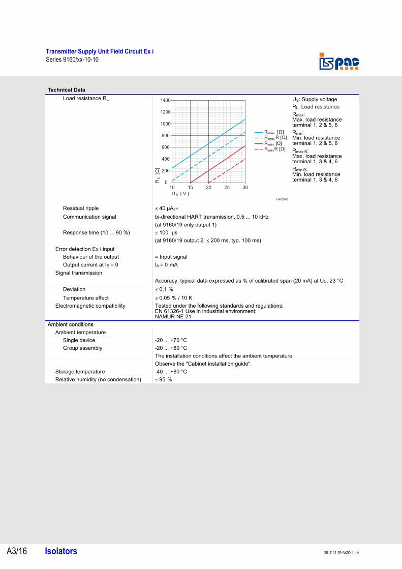
Load resistance RL
Residual ripple ( 40 μAeff
Communication signal bi-directional HART transmission, 0.5 ... 10 kHz(at 9160/19 only output 1)
Response time (10 ... 90 %) ( 100 μs (at 9160/19 output 2: ( 200 ms, typ. 100 ms)
Error detection Ex i inputBehaviour of the output = Input signalOutput current at IE = 0 IA = 0 mA
Signal transmissionAccuracy, typical data expressed as % of calibrated span (20 mA) at UN, 23 °C
Deviation ( 0,1 %Temperature effect ( 0.05 % / 10 K
Electromagnetic compatibility Tested under the following standards and regulations: EN 61326-1 Use in industrial environment; NAMUR NE 21
Ambient conditionsAmbient temperature
Single device -20 ... +70 °CGroup assembly -20 ... +60 °C
The installation conditions affect the ambient temperature.Observe the "Cabinet installation guide".
Storage temperature -40 ... +80 °C Relative humidity (no condensation) ( 95 %
Technical Data
15403E00
US: Supply voltageRL: Load resistanceRmax: Max. load resistance terminal 1, 2 & 5, 6Rmin: Min. load resistance terminal 1, 2 & 5, 6Rmax R: Max. load resistance terminal 1, 3 & 4, 6Rmin R: Min. load resistance terminal 1, 3 & 4, 6
0
200
400
600
800
1000
1200
1400
10 15 20 25 30
R [Ω]R R [Ω]
max
max
R [Ω]R R [Ω]
min
min
R
[
]Ω
L
U V ][S
A3
A3
A3
A3
A3
A3
A3
A3
A3
A3
A3
A3
A3
A3
Transmitter Supply Unit Field Circuit Ex iSeries 9160/xx-10-10
Isolators A3/172017-11-29·AK00·III·en
Technical Data
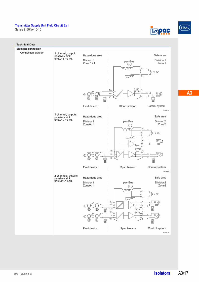
Electrical connectionConnection diagram 1 channel, output:
passive / sink9160/13-10-10.
15328E02
1 channel, outputs: passive / sink9160/19-10-10.
15329E02
2 channels, outputs: passive / sink9160/23-10-10.
15330E02
pac-Bus
Hazardous area Safe area
Field device ISpac Isolator Control system
Division 1Zone 0 / 1
Division 2Zone 2
Hazardous area Safe area
Field device ISpac Isolator Control system
Division1Zone0 / 1
Division2Zone2
pac Bus-
Hazardous area Safe area
Field device ISpac Isolator Control system
Division1Zone0 / 1
Division2Zone2
pac Bus-
Transmitter Supply Unit Field Circuit Ex iSeries 9160
Isolators 2017-11-29·AK00·III·enA3/18
Series 9160
Technical Data
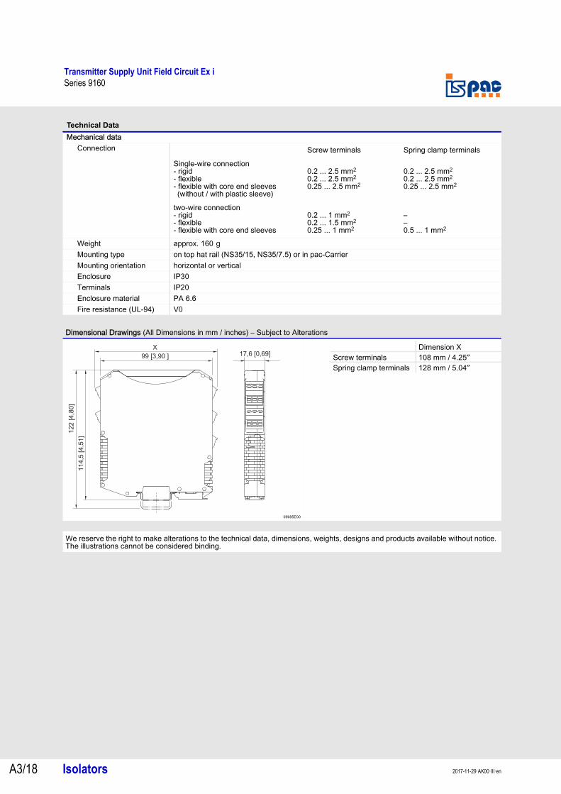
Mechanical dataConnection
Weight approx. 160 g Mounting type on top hat rail (NS35/15, NS35/7.5) or in pac-CarrierMounting orientation horizontal or verticalEnclosure IP30Terminals IP20Enclosure material PA 6.6Fire resistance (UL-94) V0
Dimensional Drawings (All Dimensions in mm / inches) – Subject to Alterations
09685E00
We reserve the right to make alterations to the technical data, dimensions, weights, designs and products available without notice. The illustrations cannot be considered binding.
Screw terminals Spring clamp terminals
Single-wire connection- rigid- flexible- flexible with core end sleeves (without / with plastic sleeve)
0.2 ... 2.5 mm2
0.2 ... 2.5 mm2
0.25 ... 2.5 mm2
0.2 ... 2.5 mm2
0.2 ... 2.5 mm2
0.25 ... 2.5 mm2
two-wire connection- rigid- flexible- flexible with core end sleeves
0.2 ... 1 mm2
0.2 ... 1.5 mm2
0.25 ... 1 mm2
–
–
0.5 ... 1 mm2
X
122 4 8
0[
,]
114,5
4 5
1[
,]
99 3 90[ , ] 17,6 [0,69]Dimension X
Screw terminals 108 mm / 4.25″Spring clamp terminals 128 mm / 5.04″