Embed Size (px)
Citation preview

1REV 3 - 1711221450 L-A2-258ROBERT H. PETERSON CO. • 14724 East Proctor Avenue, City of Industry, CA 91746
EPIC BURNER GAS LOG SET
Instructions
IMPORTANT: READ THESE INSTRUCTIONS CAREFULLY BEFORE STARTING
INSTALLATION OF YOUR LOG SET
The Peterson Real Fyre gas log set is to be installed only in a solid-fuel burning fi replace with a working fl ue constructed of noncombustible material. Solid-fuels shall not be burned in a fi replace where this gas log set is installed. The installation, including provisions for combustion, ventilation air, and required minimum permanent vent opening, must conform with the National Fuel Gas Code (ANSI Z223.1/NFPA 54) and applicable local building codes. In Canada, the installation must conform with the Natural Gas and Propane Storage and Handling Installation Code (CSA-B149.1). A damper clamp is included to maintain the minimum permanent vent opening and to prevent full closure of the damper blade. The chimney damper should be fully opened when burning the log set. The log set is designed to burn with yellow fl ames; thus adequate ventilation is absolutely necessary.
INSTALLER & CONSUMER:These instructions MUST be retained
with this appliance.
Important: For safe operation and proper performance of this product and to comply with certifi cation, listings, and building code acceptances, use ONLY Peterson Real Fyre controls, parts, and accessories that have been specifi cally listed or certifi ed for use with this burner system. Use of other controls, parts, or accessories is prohibited and will void all warranties, certifi cations, listings, and building code approvals, and may cause property damage, personal injury, and loss of life.
Do not store or use gasoline or other fl ammable vapors and liquids in the vicinity of this or any other appliance.WHAT TO DO IF YOU SMELL GAS:• Open a window.• Do not try to light any appliance.• Do not touch any electrical switch; do not
use any phone in the building.• Immediately call the gas supplier from
a neighbor’s phone and follow the gas supplier’s instructions.
• If you cannot reach the gas supplier, call the fi re department.
If the information in this manual is not followed exactly, a fi re or explosion may result, causing property damage, personal injury, or loss of life.
Installation and service must be performed by an NFI Certifi ed or other qualifi ed professional installer, service agency, or
the gas supplier.
WARNING
We recommend that our gas hearth products be installed and serviced by professionals who are certifi ed in the U.S. by the National Fireplace Institute® (NFI) as NFI Gas Specialists.
MANUALLY LIT BURNERSYSTEMS
Models:EC-24(P)EC-30(P)EC-36(P)EC-48(P)EC-60(P)
Log Set:MP-(24,30,36,48,60)
Mammoth Logs
COMPLIES to applicable ANSI standards for Vented Decorative
Appliances
2REV 3 - 1711221450 L-A2-258
Table of Contents
3 PARTS LIST (24" - 30" MODELS)
4 PARTS LIST (36" - 60" MODELS)
5 FIREPLACE REQUIREMENTS
6 MINIMUM FREE OPENING AREA OF CHIMNEY DAMPER
6 INSTALLING THE DAMPER CLAMP
7 INSTALLATION
7 INSTALLING AND TESTING THE BURNER
7 ADJUSTING AIR MIXERS
7 PLACING THE LOGS
7 PLACING THE DECORATIVE LAVA ROCK
8 LOG PLACEMENT
10 MANUAL LIGHTING INSTRUCTIONS
11 LIGHTING INSTRUCTIONS - SPK-26 VALVE
11 FOR IMPROVED PILOT OPERATION
12 MAINTENANCE AND SERVICE
12 MAINTENANCE
12 SERVICE
12 FLAME APPEARANCE
13 TROUBLESHOOTING
14 WARRANTY

3REV 3 - 1711221450 L-A2-258
Parts List (24" - 30" models)Before beginning installation, be sure the gas log set is complete by comparing its contents with this Parts List. Parts may differ depending upon the size of the set purchased. Be sure you know the model number and size of your set when ordering replacement or optional parts and accessories.
Photos not to scale.
1
9
2
Contact your local Real Fyre dealer for
replacement parts and accessories.
3
24" models
4
5
6
7
8
Item No. Part No. Description
1. EC-30 Burner assembly
2. CK-5-24SP Connector kit
3. DC-1 Damper clamp
4. OCC-10 Lava Rock (qty of 4)
5. MPL-24BR Mammoth Pine rear bottom log 24"
6. MPL-30BF Mammoth Pine front bottom log 30"
7. MPL-18T Mammoth Pine top log 18"
8. MPL-18TY Mammoth Pine top log 18"
9. MPL-20T Mammoth Pine top log 20"
10. MPL-17T Mammoth Pine top log 17"
11. SPK-26 Safety Pilot Kit (included with LP models only)
Photos not to scale.
1
9
Contact your local Real Fyre dealer for
replacement parts and accessories.
3
30" models
4
5
6
7
8
10
10
Item No. Part No. Description
1. EC-24 Burner assembly
2. CK-5-24SP Connector kit
3. DC-1 Damper clamp
4. OCC-10 Lava Rock (qty of 3)
5. MPL-22BR Mammoth Pine rear bottom log 22"
6. MPL-24BF Mammoth Pine front bottom log 24"
7. MPL-15T Mammoth Pine top log 15"
8. MPL-20T Mammoth Pine top log 20"
9. MPL-17T Mammoth Pine top log 17"
10. BL-13T Mammoth Pine top log 13"
11. SPK-26 Safety Pilot Kit (included with LP models only)y)
11
211

4REV 3 - 1711221450 L-A2-258
Parts List (36" - 60" models)Before beginning installation, be sure the gas log set is complete by comparing its contents with this Parts List. Parts may differ depending upon the size of the set purchased. Be sure you know the model number and size of your set when ordering replacement or optional parts and accessories.
Item No. Part No. Description 60 48 36
1. EC-60 Valve, Pilot, Burner assembly x x x2. CK-5-24SP Connector kit x xor CK-5-18SP Connector Kit x3. DC-1 Damper clamp x x x4. OCC-10 Lava Rock (see right for qty) 6 5 45. MPL-17T Mammoth Pine top log 17" x x x6. MPL-18TY Mammoth Pine top ‘Y’ log 18" x x x 7. MPL-18T Mammoth Pine top log 18" x x 8. MPL-19T Mammoth Pine top log 19" x x9. MPL-24T Mammoth Pine top log 24" x x 10. MPL-21T Mammoth Pine top log 21" x x11. MPL-20T Mammoth Pine top log 20" x x x12. MPL-36BF Mammoth Pine front bottom log 36" xor MPL-48BF Mammoth Pine front bottom log 48" xor MPL-60BF Mammoth Pine front bottom log 60" x13. MPL-30BR Mammoth Pine rear bottom log 30" xor MPL-42BR Mammoth Pine rear bottom log 42" xor MPL-48BR Mammoth Pine rear bottom log 48" x14. LS-0006 24" Rear spacer log (2) xor LS-0005 20" Rear spacer log (2) x15. SPK-26 Safety Pilot Kit
(included with LP models only)x x x
Note: Values in bold Italics change with burner size and model log set.
MP-60 shown.
Logs 8-11 and 14 are not included with all sets.
Photos not to scale.
1
45
6
119
8
10
7
12
13
2
14
Contact your local Real Fyre dealer for
replacement parts and accessories.
3
15

5REV 3 - 1711221450 L-A2-258
Important Pre-installation Information
Fig. 5-1 Standard fi replace dimensions Check to be sure the fi replace meets venting and construction requirements for the installation of the Real Fyre gas log set (see FIREPLACE REQUIREMENTS section, below).
This burner may only be connected to natural gas.
Be sure the gas log set is properly sized for the fi replace. Improper sizing may negatively impact the proper drafting of the fi replace. Additionally, too large a log set will adversely affect the burn and hamper the proper operation of the control system. Fig. 5-1 illustrates the critical dimensions of the fi rebox.
This gas log set must be installed by an NFI Certifi ed or other qualifi ed professional installer. The installation, including provisions for combustion and ventilation air, must conform with local codes, or, in the absence of local codes, with the latest edition of the National Fuel Gas Code, ANSI Z223-1, and NFPA54.
Keep the appliance area clear and free from combustible materials, gasoline, and other fl ammable vapors and liquids.
The Real Fyre gas log is to be installed only in a fully vented, fi replace with an open damper. The chimney must be free of any obstructions. The fi replace must be designed and approved to burn wood. The fi replace fl ue must be at least 8" at its smallest dimension.
The fi replace must have a gas supply line that has been installed by a qualifi ed technician in accordance with all local codes. The gas supply line must be ½" minimum interior diameter. If the gas line to the fi replace is longer than 5', a larger diameter line may be necessary.
Be sure to clean the fi replace fl oor of any ashes or other foreign materials. It is recommended that the fi replace and chimney be inspected by a chimney sweep or other qualifi ed person before you install the Real Fyre gas log set.
Required Gas Pressure: The minimum inlet gas supply pressure for the purpose of input adjustment is
Fireplace Requirements5" of water column (w.c.) for natural gas. The maximum inlet gas supply pressure is 10.5" w.c. for natural gas.
Testing the Gas Supply System: The gas log set and its individual shut-off valve must be disconnected from the gas supply piping system while performing any tests of the piping system at pressures in excess of ½ psig. The gas log set must be isolated from the gas supply piping system by closing its individual manual shut-off valve during any pressure testing of the gas supply piping system at test pressures equal to or less than ½ psig. This is accomplished by closing the gas supply line valve required by NFPA 54. A fi replace screen must be in place when the appliance is in operation and, unless other provisions are provided, the screen shall have an opening(s) for introduction of combustion air. When glass fi replace doors are used, operate the gas log set with the doors open.
DEPTH
HEIGHT
FR ONTWIDTH OPENING
Rearwidth
He igh t
F r o n tw i d t h o p e n i n g
D e p t h
Note: It is recommended that complete fi rebox dimensions be obtained to ensure proper sizing.
Model no.Min. Fireplace Size
BTU* (x 1000)Width
Depth HeightFront Rear Nat. LP
EC-24 31" 29" 20" 26" 60 60
EC-30 38" 31" 20" 30" 84 84
EC-36 48" 44" 28" 36" 100 100
EC-48 60" 56" 28" 36" 145 145EC-60 72" 68" 28" 36" 260 190
*Nominal BTU based on gas inlet pressure. Nominal gas inlet pressure for natural gas is 5" W.C..
Important: To comply with building code acceptances, and for safe operation and proper performance of this log set, use ONLY Peterson Real Fyre parts and accessories. Use of other controls, parts, and accessories which are not designed for use with Real Fyre gas log sets is prohibited and will void all warranties, certifi cations, listings, and building code approvals, and may cause property damage, personal injury, or loss of life.

6REV 3 - 1711221450 L-A2-258
Installing the Damper Clamp
Minimum Free Opening Area of Chimney Damper
Fig. 6-2
A damper clamp (See Parts List) is provided as a means to prevent full and/or accidental closure of the fi replace damper when installed as illustrated (Fig. 6-2). When the gas log set is operating, the damper must be fully open. To install the damper clamp:
1. Open the fi replace damper.
2. Place the damper clamp (Fig. 6-1) over the damper blade as in Fig. 6-2.
3. Tighten the set screw of the damper clamp with pliers or a wrench so that it affi xes to the damper blade. The clamp must be permanently installed.
4. Should the damper clamp not fi t, install a permanent damper stop or provide some other means of preventing full and/or accidental closure of the damper such as removing the damper blade.
Open ClosedDamper clampFig. 6-1
Note: The minimum chimney height from hearth to top of chimney is 15'.
Minimum permanent free opening area of chimney damper for venting (sq. in.)For factory-built fi replaces
Chimney height 24" 30" 36" 48" 60"
15' 27 42 47 76 13620' 23 35 43 68 128
30' 17 27 34 59 119
For masonry-built fi replaces
15' 38 52 60 86 146
20' 35 47 54 78 138
30' 32 43 49 69 129
7REV 3 - 1711221450 L-A2-258
Installation
Installing and Testing the BurnerFor Nat. Models:1. Connect the gas fl exible connector to the gas stub
from the fi replace wall.
2. Place the assembled burner and grate into the center of the fi rebox.
3. Connect the other end of the gas fl ex connector to the burner.
4. LEAK TEST: Turn on the fi replace gas supply, and test at all connections for leaks using the appropriate soapy water solution. If bubbles appear, a leak is present. Turn off the gas and tighten at all connections. Repeat until no leaks are present. If a leak persists, turn off the gas supply and contact the local gas company or dealer. NEVER USE A FLAME TO CHECK FOR LEAKS.
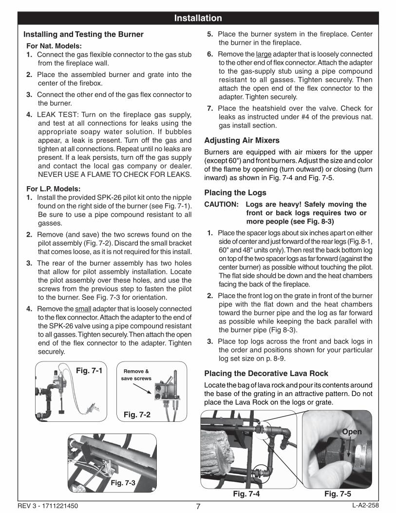
For L.P. Models:1. Install the provided SPK-26 pilot kit onto the nipple
found on the right side of the burner (see Fig. 7-1). Be sure to use a pipe compound resistant to all gasses.
2. Remove (and save) the two screws found on the pilot assembly (Fig. 7-2). Discard the small bracket that comes loose, as it is not required for this install.
3. The rear of the burner assembly has two holes that allow for pilot assembly installation. Locate the pilot assembly over these holes, and use the screws from the previous step to fasten the pilot to the burner. See Fig. 7-3 for orientation.
4. Remove the small adapter that is loosely connected to the fl ex connector. Attach the adapter to the end of the SPK-26 valve using a pipe compound resistant to all gasses. Tighten securely. Then attach the open end of the fl ex connector to the adapter. Tighten securely.
5. Place the burner system in the fi replace. Center the burner in the fi replace.
6. Remove the large adapter that is loosely connected to the other end of fl ex connector. Attach the adapter to the gas-supply stub using a pipe compound resistant to all gasses. Tighten securely. Then attach the open end of the fl ex connector to the adapter. Tighten securely.
7. Place the heatshield over the valve. Check for leaks as instructed under #4 of the previous nat. gas install section.
Adjusting Air MixersBurners are equipped with air mixers for the upper (except 60") and front burners. Adjust the size and color of the fl ame by opening (turn outward) or closing (turn inward) as shown in Fig. 7-4 and Fig. 7-5.
Placing the LogsCAUTION: Logs are heavy! Safely moving the
front or back logs requires two or more people (see Fig. 8-3)
1. Place the spacer logs about six inches apart on either side of center and just forward of the rear legs (Fig. 8-1, 60" and 48" units only). Then rest the back bottom log on top of the two spacer logs as far forward (against the center burner) as possible without touching the pilot. The fl at side should be down and the heat chambers facing the back of the fi replace.
2. Place the front log on the grate in front of the burner pipe with the fl at down and the heat chambers toward the burner pipe and the log as far forward as possible while keeping the back parallel with the burner pipe (Fig 8-3).
3. Place top logs across the front and back logs in the order and positions shown for your particular log set size on p. 8-9.
Placing the Decorative Lava RockLocate the bag of lava rock and pour its contents around the base of the grating in an attractive pattern. Do not place the Lava Rock on the logs or grate.
Fig. 7-4 Fig. 7-5
Open
Fig. 7-1
Fig. 7-3
Fig. 7-2
Remove & save screws

8REV 3 - 1711221450 L-A2-258
Log Placement
Place back bottom log (requires two to lift)
60" setup B
48" setup B
Place the burner system and rear spacer logs
60" setup A
48" setup A
Fig. 8-1 Fig. 8-2
Fig. 8-5 Fig. 8-6
Fig. 8-7 Fig. 8-8
The rear spacer logs provide a platform for rear bottom log
7
9
6
5
10
10
5
7 8
11
8 96
12
Place front bottom log (requires at least two to lift) Bottom logs in place
Fig. 8-4Fig. 8-3
1313
12
1414
Note: Reference the Parts List on page 4 for Figures 8-1 thru 9-2.

9REV 3 - 1711221450 L-A2-258
36" setup B36" setup A
Fig. 9-1 Fig. 9-2
116
9 5
Log Placement (cont.)
Note: Reference the Parts List on page 5 for Figures 9-3 thru 9-6.
30" setup B30" setup A
Fig. 9-3 Fig. 9-4
9
10
78
24" setup B24" setup A
Fig. 9-5 Fig. 9-6109
87

10REV 3 - 1711221450 L-A2-258
Lighting and Extinguishing the Burner System
1. Place a lighted long-stem match near the right end of the top burner (do not hold the match in your hand) or use a lighted long-necked butane lighter (Fig. 10-1).
2. Slowly turn the fi replace remote valve to the ONposition. The log set should light.
3. If the log set does not light before the match goes out, immediately turn the valve to the OFFposition.
4. Wait approximately fi ve (5) minutes to clear out any gas, and repeat steps 1-3 above.
5. If the log set fails to light again, turn off the valve and contact the dealer or gas supplier.
6. To extinguish the Real Fyre gas log set, simply turn the valve to the OFF position. Be sure the valve is turned fully off to avoid any gas leakage.
Cleaning and Checking
A periodic check of the following should be performed at least annually by a qualifi ed professional service representative.
1. Flue system for proper venting.2. Damper operation 3. Orifi ces for dirt or other foreign matter.4. Visual check on the burner.5. Air mixers for dust/lint blockage.6. Excessive soot on logs.
Manual Lighting Instructions
BEFORE LIGHTING, smell all around the burner area for gas. IF YOU SMELL GAS, FOLLOW THE INSTRUCTIONS ON THE COVER (P. 1).
WARNING: If you do not follow these instructions exactly, a fi re or explosion may result causing property damage, personal injury or loss of life.
Do not use this appliance if any part has been underwater. Immediately call for a qualifi ed professional service technician to inspect the appliance and to replace any part of the burner system which has been under water.
FOR YOUR SAFETY, READ BEFORE LIGHTING
Fig. 10-1

11REV 3 - 1711221450 L-A2-258
Lighting Instructions - SPK-26 Valve
For Improved Pilot Operation
Fig. 11-4
HOW TO LIGHT THE PILOTTo light the pilot from the PILOT position (Fig. 11-2), push in slightly on the knob and turn to the OFF position (Fig. 5-1). Wait fi ve minutes, then turn the knob to the PILOT position (Fig. 11-2). Push the knob fully in and at the same time place a long lighted match or long necked lighter at the pilot burner. The pilot should light. Hold the knob in approximately 60 seconds. If the pilot does not stay lit, turn to the full OFF position (Fig. 5-1). Wait fi ve minutes and repeat the LIGHTING INSTRUCTIONS.
HOW TO TURN THE GAS BURNER ON AND OFF USING THE SAFETY PILOT KIT
BE SURE THE DAMPER IS FULLY OPEN WHEN OPERATING THE GAS BURNER.
TO TURN ON THE GAS BURNER FROM THE PILOT POSITION: When the pilot is lit (Fig. 11-2), turn the knob 90° counter-clockwise to the ON position (Fig. 11-3).
TO TURN OFF THE GAS BURNER FROM THE ON POSITION (Fig. 11-3): Turn the knob 90° clockwise to the PILOT position (Fig. 11-2).
TO TURN OFF THE GAS BURNER AND THE PILOT FROM THE PILOT POSITION (Fig. 11-2): Push in slightly on the knob and turn 90° clockwise to the OFF position (Fig. 5-1).
PILOT ADJUSTMENTShould the pilot require adjustment, the following steps should be taken: With the pilot lit and the control knob in the pilot position, use a long narrow screw driver and turn the pilot adjustment screw slowly clockwise to reduce the pilot fl ame or counter-clockwise to increase the fl ame (Fig. 11-4). The adjustment screw can be turned so that the pilot fl ame is completely extinguished. Some tightening of the screw may occur during adjustment; this is normal. The pilot fl ame should be a soft blue color with slightly yellow tipping which encircles the thermocouple tip.
Turn the control knob to the ON position to assure proper ignition of the log burner.
Fig. 11-3ON positionBurner on -
pilot on
Fig. 11-2PILOT position
Burner off - pilot on
Fig. 11-1OFF position
Burner off - pilot off
Exampleof burner
pilot fl ame
3. Turn knob to ONto light burner.
1. Use OFF only when complete shutdown is necessary.
Read here
2. Turn dial to PILOTposition. With match ready, press knob in and hold for 60 seconds while lighting pilot.
Read here
Read here
* We recommend that before you install the burner you familiarize yourself with the control valve layout. This will help you to be confi dent operating the burner when fully installed (see fi gures below for typical control positions).
Pilot adjustment
12REV 3 - 1711221450 L-A2-258
Maintenance and ServiceMaintenance
Once installed and operating properly, the Real Fyre gas log set requires very little maintenance. You should inspect the log set and control annually for the following:
1. Excessive Sooting - Some sooting of the log set is normal and adds to the natural appearance of burned wood. If soot accumulates, you may brush the soot off with a stiff brush. Logs may also be cleaned by allowing them to heat up, then spraying them with water where soot has accumulated.
2. Insects and burner blockage - Check the burner ports and the air-mixer, if present, to make sure they are free from debris. Blocked burner ports and orifi ces may result in poor fl ame distribution or fl ame at air-mixer (if equipped).
Service
It is recommended that a qualifi ed professional service technician be called to service the gas log set and control should service be required. The Troubleshooting section of these instructions serves as a guide for ensuring optimum performance of the gas log set.
Flame Appearance
The fl ames should be blue at the base and a combination of blue/yellow at the body and tips.

13REV 3 - 1711221450 L-A2-258
Troubleshooting
PROBLEM CAUSE SOLUTION1. Log set Not
burning properlya. Low fl ame/uneven fl ame. a. Check for low gas pressure; minimum
operating pressures of 5" W.C. at manifold.
2. Excessive soot on logs
a. Yellow fl ame impingement a. Open air shutter on front burner or main burner as needed.
If you still experience problems with the SPK-26 safety pilot kit, please contact a local Peterson dealer.
PROBLEM CAUSE SOLUTION1. Pilot will not
lighta. Obstruction in pilot gas supply/pilot gas
supply line is kinkedb. Inadequate gas supplyc. Pilot out of adjustmentd. Air in line
a. Clear out obstruction. Replace pilot gas supply line if kinked
b. Have gas pressure checked by installer or gas supplier
c. Adjust pilot (see page 5)d. Air should clear, attempt to relight
2. Pilot will not stay lit after releasing knob
a. Pilot fl ame out of adjustment (tip of the fl ame should encircle tip of the thermocouple)
b. Thermocouple (SPK) either too tight or too loose
c. Bad thermocouple
a. Adjust pilot (see page 5)b. Thermocouple should be fi nger tight and
then 1/8" turn with a wrenchc. Replace thermocouple
3. Burner extinguishes a few minutes after lighting.
a. Inadequate gas supply causes pilot fl ame to reduce after burner lights
a. Using pilot adjustment, increase gas to pilot. Pilot fl ame must be in contact with the thermocouple tip
4. Burner extinguishes after burning for some time (approximately 10 minutes to 1 hour)
a. Thermocouple has overheated; glass doors are closed
b. Thermocouple has overheated; insulation pad is not in place
c. Thermocouple has overheated; burner fl ames are heating the thermocouple cold junction
a. Be sure glass doors are open during operation
b. Be sure that the insulation pad is in place between the burner pan and the pilot bracket
c. Be sure the pilot assembly and the fl ame diverter are in their proper position. Rearrange logs so that flame is not defl ected to the thermocouple
5. Pilot will light without holding in knob or gas fl ows to burner without pilot being lit
a. Valve is installed backward a. Reinstall valve with inlet port attached to gas supply and outlet port attached to burner
For LP Models Only:
For Nat and LP Models:
14Robert H. Peterson Co. • 14724 East Proctor Avenue • City of Industry, CA 91746
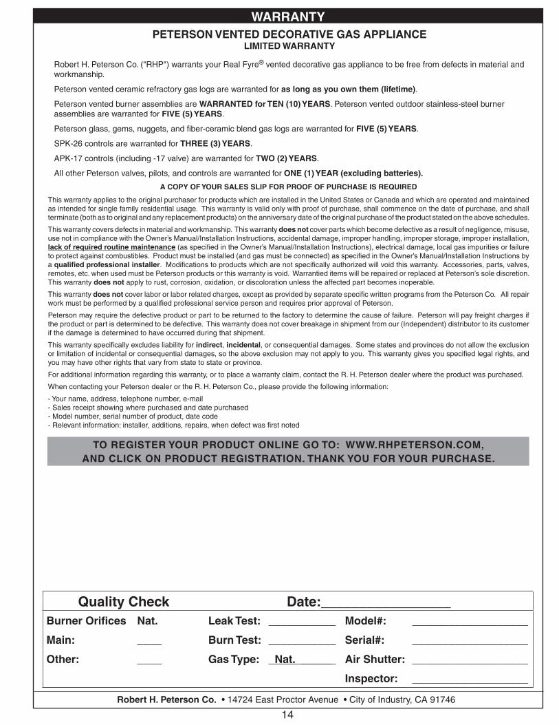
Quality Check Date:_________________Burner Orifi ces Nat. Leak Test: ___________ Model#: ___________________
Main: ____ Burn Test: ___________ Serial#: ___________________
Other: ____ Gas Type: Nat. _____ Air Shutter: ___________________
Inspector: ___________________
A COPY OF YOUR SALES SLIP FOR PROOF OF PURCHASE IS REQUIRED
This warranty applies to the original purchaser for products which are installed in the United States or Canada and which are operated and maintained as intended for single family residential usage. This warranty is valid only with proof of purchase, shall commence on the date of purchase, and shall terminate (both as to original and any replacement products) on the anniversary date of the original purchase of the product stated on the above schedules.
This warranty covers defects in material and workmanship. This warranty does not cover parts which become defective as a result of negligence, misuse, use not in compliance with the Owner’s Manual/Installation Instructions, accidental damage, improper handling, improper storage, improper installation, lack of required routine maintenance (as specifi ed in the Owner’s Manual/Installation Instructions), electrical damage, local gas impurities or failure to protect against combustibles. Product must be installed (and gas must be connected) as specifi ed in the Owner’s Manual/Installation Instructions by a qualifi ed professional installer. Modifi cations to products which are not specifi cally authorized will void this warranty. Accessories, parts, valves, remotes, etc. when used must be Peterson products or this warranty is void. Warrantied items will be repaired or replaced at Peterson’s sole discretion. This warranty does not apply to rust, corrosion, oxidation, or discoloration unless the affected part becomes inoperable.
This warranty does not cover labor or labor related charges, except as provided by separate specifi c written programs from the Peterson Co. All repair work must be performed by a qualifi ed professional service person and requires prior approval of Peterson.
Peterson may require the defective product or part to be returned to the factory to determine the cause of failure. Peterson will pay freight charges if the product or part is determined to be defective. This warranty does not cover breakage in shipment from our (Independent) distributor to its customer if the damage is determined to have occurred during that shipment.
This warranty specifi cally excludes liability for indirect, incidental, or consequential damages. Some states and provinces do not allow the exclusion or limitation of incidental or consequential damages, so the above exclusion may not apply to you. This warranty gives you specifi ed legal rights, and you may have other rights that vary from state to state or province.
For additional information regarding this warranty, or to place a warranty claim, contact the R. H. Peterson dealer where the product was purchased.
When contacting your Peterson dealer or the R. H. Peterson Co., please provide the following information:
- Your name, address, telephone number, e-mail- Sales receipt showing where purchased and date purchased- Model number, serial number of product, date code- Relevant information: installer, additions, repairs, when defect was fi rst noted
TO REGISTER YOUR PRODUCT ONLINE GO TO: WWW.RHPETERSON.COM,AND CLICK ON PRODUCT REGISTRATION. THANK YOU FOR YOUR PURCHASE.
PETERSON VENTED DECORATIVE GAS APPLIANCELIMITED WARRANTY
Robert H. Peterson Co. ("RHP") warrants your Real Fyre® vented decorative gas appliance to be free from defects in material and workmanship.
Peterson vented ceramic refractory gas logs are warranted for as long as you own them (lifetime).
Peterson vented burner assemblies are WARRANTED for TEN (10) YEARS. Peterson vented outdoor stainless-steel burner assemblies are warranted for FIVE (5) YEARS.
Peterson glass, gems, nuggets, and fi ber-ceramic blend gas logs are warranted for FIVE (5) YEARS.
SPK-26 controls are warranted for THREE (3) YEARS.
APK-17 controls (including -17 valve) are warranted for TWO (2) YEARS.
All other Peterson valves, pilots, and controls are warranted for ONE (1) YEAR (excluding batteries).
WARRANTY