Embed Size (px)
Citation preview

A1120/40 Programmable Polyphase Meter
Chapter 2 - Operating &
Maintenance Instructions
M181 001 2H 11.2011


A1120/40 - Electronic Polyphase Meter 1
Elster Metering Limited - M181 001 2H - 11/2011
1 FOREWORD ................................................................................................................................... 4
2 WARNINGS..................................................................................................................................... 5
3 COMPLIANCE WITH STANDARDS AND EUROPEAN DIRECTIVES .......................................... 6
4 APPROVALS .................................................................................................................................. 6
5 INTRODUCTION ............................................................................................................................. 7
6 GENERAL DESCRIPTION.............................................................................................................. 9 6.1 Basic Meter Types .............................................................................................................9 6.2 Current and Voltage Ratings ..............................................................................................9 6.3 System Connections ..........................................................................................................9 6.4 Terminal Arrangements ......................................................................................................9 6.5 Meter Accuracy ............................................................................................................... 10 6.6 Meter Case ...................................................................................................................... 10
7 OVER VOLTAGE OPERATION .................................................................................................... 10
8 IMPORT ACTIVE REGISTRATION .............................................................................................. 10
9 TEST INDICATORS & ANTI-CREEP ............................................................................................ 11
10 FEATURES OF THE A1120/40 METER ....................................................................................... 11 10.1 Registration of Quantities ................................................................................................ 12 10.1.1 kWh ............................................................................................................................................... 12 10.1.2 kvarh .............................................................................................................................................. 12 10.1.3 kVAh .............................................................................................................................................. 12 10.1.4 Customer Defined Registers.......................................................................................................... 13
11 TARIFF STRUCTURE ................................................................................................................... 13 11.1 Time-of-use Registers ..................................................................................................... 14 11.2 Demand Registers .......................................................................................................... 14 11.2.1 TOU Maximum Demand Registers ................................................................................................ 14 11.3 Switching Times .............................................................................................................. 15 11.4 Seasons and Change of Season Dates .......................................................................... 15 11.5 Exclusion Dates .............................................................................................................. 15 11.6 End of Billing (EOB) ........................................................................................................ 16 11.7 Daylight Savings ............................................................................................................. 17 11.8 Independent Day Control ................................................................................................ 17 11.9 Deferred Tariff and Deferred Tariff Changeover Date .................................................... 18 11.10 Tariff/Display Scheme Verification .................................................................................. 18
12 EXTERNAL REGISTERS (FIRMWARE VERSION C ONLY) ....................................................... 18
13 SECURITY FEATURES ................................................................................................................ 19 13.1 Data Retention ................................................................................................................ 19 13.2 Recordable Security Features......................................................................................... 19 13.2.1 Phase Present/Phase Fail Indication ............................................................................................. 19 13.2.2 Reverse Energy Flow .................................................................................................................... 19 13.2.3 Power Fail...................................................................................................................................... 20 13.2.4 End of Billing Event ....................................................................................................................... 20 13.2.5 Programming Event Log ................................................................................................................ 20 13.2.6 CT Ratio Programming .................................................................................................................. 21 13.2.7 Watchdog (Transient Reset) .......................................................................................................... 21

2 A1120/40 - Electronic Polyphase Meter
Elster Metering Limited - M181 001 2H - 11/2011
13.2.8 In Service Hours ............................................................................................................................ 21 13.2.9 Meter Errors................................................................................................................................... 21 13.2.10 Cover Removal Detection .............................................................................................................. 21 13.2.11 Remaining Internal Battery Life ..................................................................................................... 22 13.3 Historical Data ................................................................................................................. 22
14 METER DISPLAY ......................................................................................................................... 23 14.1 Introduction...................................................................................................................... 23 14.2 General ...................................................................................................................... 23 14.3 Display Modes ................................................................................................................. 24 14.3.1 Default Mode ................................................................................................................................. 24 14.3.2 Utility Mode .................................................................................................................................... 25 14.3.3 English Display ................................................................................................................ 25 14.3.4 OBIS Display ................................................................................................................................. 25 14.4 Displayable Data ........................................................................................................................... 26
15 USING THE PUSHBUTTONS ....................................................................................................... 27
16 COMMUNICATIONS ..................................................................................................................... 27
16.1 Optical Communications Port.......................................................................................... 27
16.2 Optional RS232 Port ....................................................................................................... 28 16.2.1 Modem Power Supply ................................................................................................................... 28 16.2.2 Resetting the Power Supply .......................................................................................................... 28
16.3 Data Stream Mode .......................................................................................................... 28
17 PROGRAMMING THE METER ..................................................................................................... 29
18 REAL TIME CLOCK AND CALENDAR ........................................................................................ 29
19 BATTERY BACK-UP .................................................................................................................... 30 19.1 Internal Battery ................................................................................................................ 30 19.1.1 Internal Battery Monitoring .............................................................................................. 30
20 MODULE/BATTERY CARRIER .................................................................................................... 31 20.1 Communications Module ................................................................................................. 31 20.2 External Battery Module .................................................................................................. 31
21 OUTPUT ........................................................................................................................................ 31 21.1 Customer Configurable Auxiliary Output (SO and Relay) ............................................... 32 21.2 Test Indication (Manufacturing option) ............................................................................ 33
22 ADDITIONAL VOLTAGE TERMINALS ........................................................................................ 33
23 LOAD PROFILE RECORDING (A1140) ....................................................................................... 33
24 INSTRUMENTATION .................................................................................................................... 34
25 TECHNICAL DATA ....................................................................................................................... 35
26 INSTALLATION ............................................................................................................................ 36 26.1 Unpacking ...................................................................................................................... 36 26.2 Handling ...................................................................................................................... 36 26.3 Storage ...................................................................................................................... 36 26.4 Installation Site ................................................................................................................ 36 26.5 Electromagnetic Compatibility (EMC) ............................................................................. 36 26.6 Fixing and Connection .................................................................................................... 37

Operating & Maintenance Instructions 3
27 COMMISSIONING ......................................................................................................................... 38
28 MAINTENANCE ............................................................................................................................ 39
29 DISPOSAL AND RECYCLING ..................................................................................................... 39
Figure 1 - Model Code .................................................................................................................. 40 Figure 1 - Model Code (Continued) .............................................................................................. 41 Figure 2 – A1120/40 Meter ............................................................................................................ 42 Figure 3 - Typical Nameplate ........................................................................................................ 43 Figure 4 - Load Curves ................................................................................................................. 44 Figure 5 - Terminal Arrangements ................................................................................................ 45 Figure 5A - Terminal Configurations ............................................................................................... 46 Figure 6 - Dimensions, Fixing Centres.......................................................................................... 47 Figure 7 - A1120/40 Displays ........................................................................................................ 48 Figure 7 - A1120/40 Displays (continued) .................................................................................... 49 Figure 8 - Display Table ................................................................................................................ 50 Figure 8 - Display Table (continued) ............................................................................................. 51 Figure 8 - Display Table (continued) ............................................................................................. 52 Figure 8 - Display Table (Instrumentation) ................................................................................... 53 Figure 9 - Password Access Levels .............................................................................................. 54
APPENDIX A - Checking kWh and kvarh Registration Accuracy .............................................................. 55 A1 Introduction ................................................................................................................... 55 A2 Checking Meter Accuracy Using the LED Test Indicator ............................................. 55 A2.1 Comparing the number of LED pulses with substandard meter register advance ....... 55 Checking registration .................................................................................................... 55 A2.2 Comparing LED pulses with substandard meter pulses ............................................................. 56 A3 Checking Meter Registration Accuracy from Register Advances ................................. 56 A3.1 Using the 'Dial Test' values on the meter display........................................................................ 56
APPENDIX B - RS232 Multi-drop Mode ..................................................................................................... 57 B1 RS232 Multi-drop Installation Procedure ...................................................................... 57
APPENDIX C - RS485 Multi-drop Mode ..................................................................................................... 58
APPENDIX D - External Battery Module .................................................................................................... 59 D1 External Battery Module ............................................................................................... 59 External Battery Status ................................................................................................. 59 Using the External Battery Facility during Power Outages .......................................... 59 D2 Installation..................................................................................................................... 60

4 A1120/40 - Electronic Polyphase Meter
Elster Metering Limited - M181 001 2H - 11/2011
1 FOREWORD
HEALTH AND SAFETY
Compliance with Instructions in this Manual
The instructions and information in this manual are provided in compliance with Section 6 of the UK Health and Safety at Work Act, as amended by Schedule 3 of the Consumer Protection Act 1987.
The purchaser is responsible for making sure that everyone, whether in his employment or not, who will be associated with the products supplied by Elster Metering Systems, and to which these instructions and information apply, are made familiar with the contents of this manual.
This applies to all persons who may be involved in activities such as unpacking, inspecting, testing, setting, cleaning, installing, commissioning, operating, maintaining, decommissioning or disposing of the products.
Safety of Persons using Electrical Products
Employers have a duty to ensure, as far as is reasonably practicable, the Health, Safety and Welfare at Work of all their employees. Employers must therefore ensure that employees are informed, trained and supervised and use proper working procedures to ensure the safety of themselves and others.
The information provided in this manual is intended to ensure that products are properly installed and otherwise handled in order to maintain them in a safe condition.
In the UK, employers have duties under the Health and Safety at Work Act 1974 and the various regulations stemming therefrom.
In countries outside the UK, employers should ensure proper compliance with the Health and Safety Legislation that is applicable to them.
Putting into Service
Products supplied by Elster Metering Systems have been designed and manufactured, in accordance with appropriate standards, to operate under specified conditions, when properly installed.
The purchaser or delegated contractor is responsible for the "Putting into Service" of any Elster Metering Systems products that have been supplied as "Non-connected". All related activities must therefore be carried out with due regard to any applicable legislation, standards and good practice.

Operating & Maintenance Instructions 5
2 WARNINGS
WARNINGS
Internal Electronic Circuits
Parts of the internal electronic circuits of these meters are, due to technical necessity, connected to PHASE VOLTAGES.
Dangerous voltages are present
A Terminal Cover Plate must always be fitted to the A1120/40 meter to protect the main meter terminals. If the Terminal Cover Plate is not fitted to the A1120/40 meter, all supplies to the meter must be isolated before a module, module peripheral equipment or external battery module is installed or removed.
Failure to do so may result in electric shock.
Caution
Installation of a faulty module or module peripheral equipment may affect the main meter
functionality.
Removal of the main cover invalidates the certification of certified meters.
Liquid Crystal Display
Liquid crystals are toxic. If a display is damaged, avoid contact with the liquid. If the liquid makes contact with the skin it must be washed off immediately with water.
Seek medical advice.
Batteries
The meter contains an internal Lithium manganese dioxide primary cell. This battery is completely
safe under normal conditions. However, it must never be recharged, disassembled, heated above
100° C, incinerated, or have the contents exposed to water.
Fire, explosion or severe burns may result if these instructions are disregarded.
In the interests of safety, environmental protection and possible legislation, Lithium batteries require
careful disposal. Before arranging for the disposal of these cells, users should satisfy themselves
that the proposed means of disposal is both safe and compliant with local legislation requirements.
Elster Metering Systems would like to draw the user's attention to the International Standard for
Lithium Batteries - IEC 60086-4 - which gives further information about the handling, storage,
transport and disposal of lithium cells.
Elster Metering Systems should be contacted by the user should difficulties arise in arranging proper disposal. They will if practical help the user identify safe disposal means.
An optional External Battery Module supports the display and optical communications during power outages. A non-rechargeable “alkaline” (alkaline zinc manganese dioxide) PP3 (IEC 6LR61) battery is used.
This battery is completely safe under normal conditions. It must not be recharged, disassembled, short-circuited, overheated or incinerated. It contains corrosive materials.
Used batteries should be disposed of in compliance with local legislation requirements.

6 A1120/40 - Electronic Polyphase Meter
Elster Metering Limited - M181 001 2H - 11/2011
3 COMPLIANCE WITH STANDARDS AND EUROPEAN DIRECTIVES
Meters are marked with the European CE mark, in accordance with the Marking Directive 93/68/EEC, to indicate compliance with the requirements of the EMC Directive 89/336/EEC.
Safety requirements for meters are addressed in specific metering standards outlined below.
The CE Mark does not denote compliance with the European Low Voltage Directive 73/23/EEC, which specifically excludes electricity meters.
The A1120/40 meter measures active energy, according to the requirements of - EN 62053-21/22:2003 for indoor kWh meters of Protective Class II and Accuracy Class 0.5s, 1 or 2 (MID) - Annex MI-003, kWh Class A, B or C.
The meter measures reactive energy in accordance with EN 62053-23:2003, Class 2 or Class 3.
Meters displaying OBIS Identification Codes meet the requirements of IEC 62056-61.
The degree of ingress protection is to IP53, IEC 60529:1989.
The meter complies with DIN 43857 Part 2 and Part 4 - dimensional requirements (except for the top fixing centres).
The meter complies with the essential requirements of the EC Directive 2004/22/EC on Measuring Instruments (MID).
The meter complies with the general requirements and particular requirements of EN 50470 Parts 1 & 3, and complies with Class M2 Mechanical environment and Class E2 Electromagnetic Environment.
Devices for metering and billing electrical energy described in this manual are supplied for use in a „Fixed Installation‟ only. Devices described are a „component of a system only‟ and therefore outside the scope of European Directives 2002/95/EC RoHS (Restriction of the Use of Certain Hazardous Substances in Electrical Equipment) and 2002/96/EC WEEE (Waste Electrical and Electronic Equipment).
4 APPROVALS
kWh/kvarh energy meters are approved by the Office of Gas and Electricity Markets (OFGEM) in compliance with European and British metering legislation.

Operating & Maintenance Instructions 7
5 INTRODUCTION
The A1120/40 has been designed to meet the changing needs of the Electricity Supply Industry.
The meter offers a „modular‟ solution for remote communications, allowing the meter to be integrated into an AMR system at any time. Flexibility in communications provides the Utility with the means to employ the most cost effective communications method. The RJ11 connector provides power for a modem removing any requirement for external connections. The modem fits neatly under the terminal cover providing a high degree of protection against fraud or tampering.
Communications are provided via the optical (IEC 62056-21) port and are supported by data stream mode, allowing fast reading of meter data. The A1140 permits up to 90 days of load profile data to be collected in less than 30 seconds. The RJ11 socket provides optional RS232 communications allowing remote access to the same data as the optical port. This port can be multi-dropped, allowing access to up to 10 meters in a single installation. A further option allows a pulsed output to be transmitted via the meter‟s auxiliary terminals.
The meter is available in a number of variants that measure combinations of active energy, four quadrant reactive energy and kVAh. Two customer defined registers can be used to summate energy from any like unit registers. Instrumentation quantities to aid installation can be included in the display sequence.
Firmware Version C allows 12 External Registers to display data from an external source such as a gas or water meter. The registers are written to by an intelligent source via the RS232 port.
The meter offers extensive security data which includes a programming log with user ID. Further security can be provided as an option with terminal cover and main cover removal detection. As an alternative option, the latter detection switch can instead be used to allow the CT ratio to be changed.
The Liquid Crystal Display (9.8mm) has large characters that can be viewed from a wide angle. The display sequence is programmable and can be auto-cycle, step or utility. Displayed information can have English language identifiers or OBIS (Object Identification System) codes. The OBIS codes can be changed via the Power Master Unit.
Power Master Unit software provides a user-friendly WindowsTM
graphical interface for programming the meter and reading meter data.
The meters are approved to:
EN 62053-21/22 for kWh accuracy - Class 0.5s, 1 or 2 EC Directive 2004/22/EC (MID) - Class A, B or C EN 62053-23 for kvarh accuracy - Class 2 or Class 3
The meter has an ingress protection rating of IP53 to IEC 60529:1989.
The following main variants of the meter (configured at manufacture) are available:
Import kWh
Import kWh, Q1 and Q4 kvarh
Import kWh, Q1, Q2, Q3, Q4 kvarh, kVAh 1
Import/Export kWh
Import/Export kWh, Q1, Q2, Q3, Q4 kvarh
Import/Export kWh, kVAh 1-2
Import/Export kWh, Q1, Q2, Q3, Q4 kvarh, kVAh 1-2
Import/Export kWh, Q1, Q2, Q3, Q4 kvarh, kVAh 1-2, Cumulative Import/export kWh phase A, B and C (Model Code Feature Set F only)

8 A1120/40 - Electronic Polyphase Meter
Elster Metering Limited - M181 001 2H - 11/2011
The main available manufacturing options of the meter are tabulated below:
A1120 A1140
Pulse Output Optional Optional
Load Profile Not available Standard
RS232 Port Optional Optional
Accuracy EN 62053 - 21/22(kWh) 2004/22/EC (MID)
Class 0.5s, 1 or 2 Class A, B or C
Class 0.5s, 1 or 2 Class A, B or C
Features
Accuracy kWh Class 0.5s, 1 or 2 (EN 62053 -21/22) kWh Class A, B or C (EC Directive 2004/22/EC [MID])
kvarh Class 2 or Class 3
Comprehensive tariff structure
Twelve external registers (Firmware Version C only)
Large digit (9.8 mm register digits) Liquid Crystal Display
IEC 62056-21 (formerly IEC 61107) optical communications port
Internal clock and calendar with battery back-up
15 years product life
Comprehensive security data
Display of external register information
Compact design
DIN (BS) double insulated, glass filled polycarbonate case
IP53 in accordance with IEC 60529 : 1989
Options
RS 232 serial communications
Load profiling (A1140)
Module/battery carrier
SO (EN 62053-31) or relay pulsed output
Terminal cover removal detection switch
Main cover removal detection or CT ratio programming switch
Terminal cover with cut-out
Read without power option (battery support)
Tariff Structure
8 time-of-use (TOU) registers
4 maximum demand registers
48 switching times
12 seasons
24 change of season dates
32 exclusion dates
Daly Billing (Model Code Feature Set F only)
13 end of billing dates
Independent day control Daylight saving Deferred tariff Tariff scheme CRC

Operating & Maintenance Instructions 9
6 GENERAL DESCRIPTION
6.1 Basic Meter Types
LM… DIN/BS Termination
6.2 Current and Voltage Ratings
Unless otherwise indicated on the nameplate, the following meter ratings are available:
Voltage Current Frequency
3 Element Meters
*220 - 240V L-N
105 - 127V L-N
2 Element Meters
220 - 240V L-L
105 - 127V L-L
20 - 100A (Direct connected)
10 - 100A (Direct connected)
5 - 100A (Direct connected)
1 - 2A (CT operated)
*5 - 10A (CT operated)
1 - 10A (CT operated)
50 or 60Hz
* Ratings available for Class 0.5s, CT operated variant
Note - 105 - 127V meters and 60Hz meters are not OFGEM or MID approved.
6.3 System Connections
Meters can be supplied for direct connected or CT, 3 element (3 phase, 4 wire) or 2 element (3 phase 3 wire) applications and have the following connection capability:
Number of Elements Connection capability
3 * 3 phase, 4 wire
2 phases of 3 phase, 4 wire
2 phase, 3 wire
1 phase, 3 wire
1 phase, 2 wire
2 * 3 phase, 3 wire
* Connections available for Class 0.5s, CT operated variant
6.4 Terminal Arrangements
Current Terminals
8.2mm diameter bore, 2 x M6 Combi pinch screws
9.0mm diameter bore, 2 x M6 Combi pinch screws
9.5mm diameter bore, 2 x M6 Combi pinch screws
Auxiliary Terminals 3.2mm diameter bore, M3 Combi pinch screws
Meter nameplates (see Figure 3 for example) are marked with the rated current, reference voltage, frequency and the relevant meter constant (pulses/kWh, pulses/kvarh).
Connection diagrams (See Figure 5A for examples) are shown underneath the terminal cover.
A Terminal Cover Plate must be fitted to protect the meter Main Terminals.

10 A1120/40 - Electronic Polyphase Meter
Elster Metering Limited - M181 001 2H - 11/2011
6.5 Meter Accuracy
The A1120/40 meter measures active energy, in accordance with the requirements of -
EN 62053-21/22 for indoor kWh meters of protective Class II and accuracy Class 0.5s, 1 or 2,
EC Directive 2004/22/EC (MID) - Class A, B or C
The design of the meter ensures life long stability. There are no on-site adjustments.
The meter measures reactive energy in accordance of the requirements of EN 62053-23 for
kvarh meters for reactive energy Class 2 or Class 3.
Typical accuracy curves are shown in Figure 4.
6.6 Meter Case
The case is double insulated to protective Class II.
The case provides an ingress protection rating of IP53 in accordance with IEC 60529:1989.
The base is light beige coloured polycarbonate.
A separate phenolic terminal block conforms to DIN 43857 Part 2 and 4.
The extended terminal cover is moulded in light beige coloured polycarbonate. An option with a cut-out is available.
The main cover is moulded in tinted, clear polycarbonate.
Figure 6 illustrates the outline and fixing dimensions.
The main cover is secured by two sealable screws. Two separate sealable screws secure the terminal cover.
The terminal cover plate protects the meter main terminals.
A holder for a module/battery that attaches to the base under the terminal cover is available as an option.
7 OVER VOLTAGE OPERATION
The meter has been designed to withstand a phase - neutral voltage of √3 x 1.1 Uref (i.e. 440V for 230V meters) for an indefinite period. When tested over a 12 hour duration the change in meter error was less than 0.4%.
8 IMPORT ACTIVE REGISTRATION
Import Active registration can be configured at manufacture to one of the following:
Import Active Units Only – Import Active Units measures the sum of all phases, when the total system flow is positive.
Positive (kWh [L1] + kWh [L2] + kWh [L3])
Power Flow Insensitive Mode - Power Flow Insensitive Mode allows the meter to increment its main kWh register regardless of whether the system energy flow is import or export.
│(kWh [L1] + kWh [L2] + kWh [L3])│

Operating & Maintenance Instructions 11
The Reverse Energy Event Alarm, Reverse Energy Count and Reverse kWh Register respond only to reverse power flow and continue to function as in normal operation.
Theft Resistant Measurement - Theft Resistant Measurement mode measures the sum of the modulus of each phase (│kWh [L1]│ + │kWh [L2]│ + │kWh [L3]│)
The Reverse Energy Event Alarm, Reverse Energy Count and Reverse kWh Register respond only to reverse power flow and continue to function as in normal operation.
Note 1: Power Flow Insensitive Mode and Theft Resistant Measurement may not be allowed in certain countries due to local regulations.
Note 2: Theft resistant measurement is not appropriate for meters connected to 3 phase 3 wire systems.
9 TEST INDICATORS & ANTI-CREEP
Test Indicators
Two red test output LEDs (for kWh and kvarh) are provided which pulse in accordance to the following configurations:
Import only meter - The LED pulses for forward system energy only
Import meter with Power Flow Insensitive enabled - The LED pulses for forward and reverse system energy
Import meter with Theft Resistant measurement enabled – The pulsing LED reflects theft resistant measurement.
Import/export meter - The LED pulses for import and export energy
See Section 25 (Technical Data) for LED specification.
Anti-creep
The Wh and varh anti-creep threshold is set at manufacture to a value appropriate to the meter rating and accuracy class. For a 4 wire meter connected with less than 3 elements energised, the value adjusts to maintain an appropriate current threshold level. Each Test Indicator LED is continuously illuminated when the meter's anti-creep lock is operating for kWh and kvarh respectively.
10 FEATURES OF THE A1120/40 METER
The meter contains numerous features, combinations of which can be selected to provide the required metering function. Main variants are selected at manufacture (See Section 5). Programmable features are selected using Power Master Unit Software that runs on an IBM or compatible PC.
This software is available from Elster Metering Systems and is described in M181 001 3.
Note: The features available will depend on the meter variant (See Section 5).

12 A1120/40 - Electronic Polyphase Meter
Elster Metering Limited - M181 001 2H - 11/2011
10.1 Registration of Quantities
10.1.1 kWh
kWh total import (active energy)
kWh total export (active energy)
Total import and total export quantities are registered separately. The measurement discrimination is such that, as the power factor of any load from 0.05Ib to Imax is varied over 360°, the import and export registers will never advance together. The resolution of registration is 1mWh.
(Model Code Feature Set F only) A cumulative kWh record for each phase is recorded as follows:
Import kWh phase A, B and C
Export kWh phase A, B and C
10.1.2 kvarh
Q1 kvarh Inductive Import
Q2 kvarh Capacitive Import
Q3 kvarh Inductive Export
Q4 kvarh Capacitive Export
All four quadrants are registered separately. The resolution of registration is 1mvarh.
kvarh is derived using the phase shift method.
Note: The diagram shows a representation of the quadrants. The active quadrant can be shown on the display.
10.1.3 kVAh
kVAh is derived from the measured kWh and kvarh values
The calculation uses the formula: kVAh = ([kWh]2 + [kvarh]
2 )
There are two kVAh registers. These can each be configured to accept pulses from any combination of quadrants e.g.
Q1 Q2 Q3 Q4
kWh * * kVAh - to match 2 electromechanical meters
kvarh * *
Note: Real and reactive energy for each phase is respectively summated prior to kVAh calculation.
E
XPO
RT A
CTIV
E PO
WER
IM
PO
RT REACTIVE PO
WER
E
XPO
RT REACTIVE PO
WE
R
Q1Q2
Q3 Q4
+Q
-Q
+P-P
Lagging/In
duct
ive
L
eadin
g/C
ap
acitiv
e
Lagging/Inductive
Leading/C
apacitive

Operating & Maintenance Instructions 13
10.1.4 Customer Defined Registers
Two Customer Defined (CD) Registers are provided. These are cumulative registers which can be used throughout the tariff scheme and load profile data and are programmable to accept consumption from any two of the following like-unit registers:
kWh import
kWh export
Q1 kvarh
Q2 kvarh
Q3 kvarh
Q4 kvarh
kVAh 1
kVAh 2
Import kWh phase A, B or C (Model Code Feature Set F only)
Export kWh phase A, B or C (Model Code Feature Set F only)
Examples of their use are:
CD Register 1 Total kWh kWh import + kWh export = Total kWh
CD Register 2 Total Import kvarh Q1 + Q2 = Total Import kvarh
The contents of the Customer Defined Registers can be viewed on the display.
11 TARIFF STRUCTURE
The tariff structure repeats year on year and comprises the following features: 8 Time-of-use (TOU) registers 4 Maximum demand registers 48 Switching times 12 Seasons 24 Change of season dates 32 Exclusion dates Daily Billing (Model Code Feature Set F only) 13 End of billing dates Daylight savings Independent day control Deferred tariff Tariff scheme CRC
At least one Season must be programmed into the meter for TOU registers to be available.

14 A1120/40 - Electronic Polyphase Meter
Elster Metering Limited - M181 001 2H - 11/2011
11.1 Time-of-use Registers
A total of 8 Time-of-use (TOU) registers are provided. Each TOU register has a single source that can be selected from one of the following:
Import kWh
Export kWh
Q1 kvarh
Q2 kvarh
Q3 kvarh
Q4 kvarh
kVAh 1
kVAh 2
kWh Import Phase A, B, or C (Model Code Feature Set F only)
kWh Export Phase A, B or C (Model Code Feature Set F only)
Customer Defined Register 1
Customer Defined Register 2
Each TOU Register is independently time controlled so that registration can take place over a restricted time period.
The contents of each TOU Register can be viewed on the display along with the active rate(s).
11.2 Demand Registers
The A1120/40 provides the rising demand value associated with each of the registered quantities specified in Section 11.1. The demand integration period can be 1, 2, 3, 4, 5, 6, 10, 15, 20, 30 or 60 minutes.
In A1140 meters the integration period used for the demand registers is the same as the load profile integration period.
During any period, the rising demand value is calculated by measuring the energy consumed to a point in a period, then scaling the measured value by a factor equal to the ratio of the demand period to a total hour interval.
Rising Demand = Energy recorded in current period x 60 p minutes in demand period
The contents of each Rising Demand Register can be viewed on the display.
11.2.1 TOU Maximum Demand Registers
The meter has 4 maximum demand registers, each with an independent source selectable from one of the rising demands.
The meter records the three highest maximum demand values (along with time and date stamp) that can be sampled on a continuous basis (24-hour period) or over a restricted time period. At the end of each billing period, the greatest of the three demands is added to a corresponding cumulative maximum demand register. The maximum demand registers are then set to zero.

Operating & Maintenance Instructions 15
11.3 Switching Times
Up to 48 switching times can be set, each allocated to a specified season. Each switching event can be enabled for any combination of days of the week. These are the transition times when one or more TOU registers become active or inactive.
Each switching time is defined in hours and minutes. A 24-hour clock is used.
The above diagram shows the tariff for TOU1 and TOU2. TOU1 is active from 06:00 to 18:00. TOU2 is active from 18:00 to 06:00. It is possible for none or multiple TOU registers to be programmed to be active at any particular time period.
11.4 Seasons and Change of Season Dates
Up to 12 Seasons may be specified and at least one Season must be programmed for the TOU registers to be available. Each Season is activated by one or more Change of Season Dates.
Up to 24 Change of Season Dates are available, each date specifying the start of a new Season. These may refer to a different Season, or the same Season may be used more than once in a year.
The old Season ends at the instant the new Season starts. A new Season starts at 00.00 of the specified day. Start dates are specified as absolute (dd.mm) dates.
The diagram shows three Seasons. Season 1 is in operation from October to February, Season 2 from March to May and Season 3 from June to September.
11.5 Exclusion Dates
There may be special days in the year when the tariff does not follow the normal pattern, e.g. public holidays. These can be taken care of by invoking Exclusion Dates.
Up to 32 Exclusion Dates can be programmed.
06:00 18:00
24 hours
Switching times

16 A1120/40 - Electronic Polyphase Meter
Elster Metering Limited - M181 001 2H - 11/2011
These dates will fall into one of three categories:
1 Dates which are fixed for every year e.g. December 25th - programmed by absolute dd.mm
2 Dates which fall on the same day of the month every year e.g. the first Monday in May
3 Dates which vary from year to year e.g. Easter Monday - defined using dd.mm.yy
For each Exclusion Date the meter may be programmed to:
- Use the switching times for a different weekday of the current season
- Use the switching times for the same weekday but a different season
- Use the switching times for a different weekday of a different season
11.6 End of Billing (EOB)
End of Billing Reset
Time and Date Stamps forthe last three EOB records
Programmed EOB
Instantaneous EOB
Automatically on programmed dates (13 or 36) and every midnight when Daily Billing is enabled At a change of season date (24) When the deferred tariff becomes active Daily Billing
When the Billing Reset pushbutton is pressed On command via the optical port On command via the serial port (where fitted) When a CT ratio programming event occurs
When the internal battery has failed at power up
When a snapshot of meter data is required to allow a bill to be prepared reflecting consumption to a specified date, the End of Billing feature should be used (See Section 13.3 for a description of the data captured).
An Automatic End of Billing can be programmed for:
13 dates (model code number)
36 dates (model code number)
More than one End of Billing request may occur at the same time (for example, a deferred tariff introduced at the start of a new season), but only a single End of Billing event will take place. The cause of each of the End of Billing events is recorded but the End of Billing Counter is only incremented by one.
If an End of Billing Reset is required when the current tariff is manually overwritten by a new current tariff, it should be manually requested as part of the communications session.
A message that a Billing Reset has been initiated is displayed with a code showing the cause of
the reset (See Figure 8, Display Table).
At each Billing Reset the oldest of the fifteen historical data records is overwritten. Time and
date stamps, together with causes are stored for the last three End of Billing events.

Operating & Maintenance Instructions 17
Mon Tue Wed Thu Fri Sat Sun
1 2 3 Switching programs
End of Billing Lock-out
A further End of Billing can be inhibited via the Power Master Unit for either:
- Up to 255 minutes
- Until the next midnight boundary
Note: This only inhibits instantaneous end of billing requests, either via the pushbutton or communications setting, not programmed End of billing events.
Model Code Feature Set F only)
A Daily End of Billing occurs every midnight. A maximum of 14 records are stored (See Section 13.3 for a description of the data captured).
If a Daily End of Billing event should have occurred during a power down, then a billing event will take place immediately following the next power up. If several requests were missed then a single billing event is created, the cause reflecting all billing events that were missed.
Daily Billing initiates a Billing Reset every midnight. When Daily Billing is enabled there is an
option to inhibit the reset of the Maximum Demand Registers.
11.7 Daylight Savings
The meter provides 2 Daylight Savings dates whereby the clock can be advanced by one or two hours at the start of the summer and can be retarded by one or two hours at the end of the summer.
The day on which a Daylight Saving occurs is programmable, with the choice of the first, second, third, fourth or last specified weekday in a specified month.
The algorithm used will identify the correct calendar dates for the next 50 years.
All of the following will reflect Daylight Savings:
Automatic End of Billing
Switching times within the tariff definition
Time and date stamps (For firmware Version C meters, daylight savings time and date stamps can be referenced to base time or daylight savings time)7.
Optionally load profile (A1140 only)
11.8 Independent Day Control
The meter has the facility to have a different switching program consisting of several switching times running on different days of the week. An example of a switching program is below.

18 A1120/40 - Electronic Polyphase Meter
Elster Metering Limited - M181 001 2H - 11/2011
11.9 Deferred Tariff and Deferred Tariff Changeover Date
A second tariff can be programmed in the meter that will take effect from a programmed date.
An option to perform an End of Billing on the Deferred Tariff Changeover Date is available as part of the deferred tariff structure.
11.10 Tariff/Display Scheme Verification
The meter generates a checksum (CRC-16) of the tariff/display scheme currently residing in the meter. The checksum can be included as part of the display sequence, and also compared with a tariff checksum generated by the Power Master Unit. This allows quick verification, either locally or remotely, that the correct tariff/display scheme resides within the meter.
12 EXTERNAL REGISTERS (FIRMWARE VERSION C ONLY)
Firmware Version C of the A1120/40 has 12 External Registers that can be used to display data from an external source such as a gas or water meter. The registers are accessed via an intelligent source (such as a modem) and can be viewed on the A1120/40 meter display.
The registers are configured as three sets, External set 1, External set 2 and External set 3.
Each register set has four associated registers and has its own formatting options that can be configured using the Power Master Unit (Number of digits, Number of decimal places and display scale).
The Display shows Register 2 of External Set 1
Each register has 16 digits. The user is able to select English text or create an OBIS code for each of the twelve external registers.

Operating & Maintenance Instructions 19
13 SECURITY FEATURES
Password Protection
The A1120/40 meter uses a Password as part of the security algorithm. The passwords must be entered in upper case. Password protection can be disabled at manufacture if required. Four levels of access are available.
Entering the correct password for levels 0, 1, 2 and 3 allows the functions in Figure 9 to be performed, higher levels giving access to the lower levels. Passwords may also be set to defaults using the Power Master Unit.
It is important to note that the integrity of the A1120/40 meter passwords should always be protected. This can be achieved by ensuring the ability to change passwords is controlled and only made available to Administrative Personnel. The level 3 password should be changed at regular intervals. It may be appropriate for no more than 100 meters to be protected by the same level 3 password.
Calibration values, zeroing of registers etc. are protected by a security link that is removed at the factory before the meter is sealed.
13.1 Data Retention
All cumulative register and time of use data is saved to non-volatile memory every time the power to the meter fails and also every 2 hours. The data is recovered when power is restored to the meter.
All data is retained for the nominal life of the meter.
13.2 Recordable Security Features
The following security features are available and can be included in the display sequence:
13.2.1 Phase Present/Phase Fail Indication
The meter detects and stores the number of phase fail events to a maximum of 65535. The register will then roll over to 0. A time and date stamp of the three most recent events is recorded. The phase fail threshold can be set between 0 and 250 V. Phase indication on the display (L1, L2, L3) has the following options:
Indicator „on‟ when phase present
Indicator „on‟ when phase failed
Where a meter is to be used on a supply with less than 4 wires, it is possible to disable the monitoring and display of phases L2 and L3.
13.2.2 Reverse Energy Flow
Reverse run event count
The meter detects and stores the number of reverse running events to a maximum of 65535. The register will then roll over to 0.
A time and date stamp of the three most recent events is recorded.

20 A1120/40 - Electronic Polyphase Meter
Elster Metering Limited - M181 001 2H - 11/2011
The count and time and date stamps can be included in the display sequence. An event is detected if the meter runs in reverse for a period greater than 5 seconds.
Reverse energy reading
Irrespective of whether the meter is set to import only power flow insensitive mode, reverse kWh power flow will be independently recorded.
Theft Resistant Measurement
Theft Resistant Measurement mode measures the sum of the modulus of each phase (│kWh [L1]│ + │kWh [L2]│ + │kWh [L3]│)
The Reverse Energy Event Alarm, Reverse Energy Count and Reverse kWh Register respond only to reverse power flow and continue to function as in normal operation.
Reverse energy Alarm (Import only meter)
The reverse run indication, which responds to the total system power flow, can be inhibited if required.
Per Phase Reverse Run Indication
Any phase in reverse run can be indicated on the Liquid Crystal Display by flashing the L1, L2 or L3 phase indicators.
13.2.3 Power Fail
A count of the cumulative number of power downs to a maximum of 65,535 is recorded. The register will then roll over to 0.
A time and date stamp of the three most recent events is recorded. The count and time and date stamps can be included in the display sequence.
13.2.4 End of Billing Event
A count of the number of end of billing events to a maximum of 65,535 is recorded. The register will then roll over to 0. Time and date stamps together with the source of the billing reset for the three most recent events is recorded. The count and time and date stamps can be included in the display sequence. The message „Reset‟ is displayed each time an End of Billing event takes place.
13.2.5 Programming Event Log
A count of the number of programming events to a maximum of 65,535 is recorded. A time and date stamp of the three most recent events together with the source (optical or RS232 data port) is recorded. The identity of the programming user is also stored. The count and time and date stamps can be included in the display sequence.
Note: Programming events are communications sessions where the meter configuration or data has been changed. Reading data only does not count as a programming event.

Operating & Maintenance Instructions 21
13.2.6 CT Ratio Programming
The CT ratio can be displayed as a ratio or as a scalar quantity. A count of the number of CT Ratio reprogramming events to a maximum of 65,535 is recorded together with source (Optical or RS232 port) and time and date stamps for the three most recent events. The identity of the programming user is also stored. The count and time and date stamp can be included in the display sequence.
Note: CT Ratio Reprogramming Events are communications sessions where the primary or secondary value of the CT has been changed.
An End of Billing Reset can be requested with a CT ratio change.
A CT Programming switch can be fitted as a manufacturing option. The switch must be activated in order to change the CT ratio. The switch is under the terminal cover and may be protected by a paper seal.
13.2.7 Watchdog (Transient Reset)
A count of the number of watchdog resets to a maximum of 65,535 is recorded together with time and date stamps for the three most recent events. The count and time and date stamps can be included in the display sequence.
13.2.8 In Service Hours
The elapsed time counter records the cumulative time (to a resolution of 1 hour) the meter has been powered up. The count can be included in the display sequence.
The amount of storage is in excess of 25 years.
13.2.9 Meter Errors
An alarm can be displayed if an error occurs. The alarm and error message (See Figure 8, Display table) can be disabled via the Power Master Unit.
Access to the data is via the optical port, the RS232 data port or on the LCD. A time and date stamp of the three most recent non-fatal error events is recorded where possible.
In the unlikely event that any of the above meter errors occur, a catastrophic failure has been detected and the meter should be returned to Elster Metering for failure investigation.
13.2.10 Cover Removal Detection
Main Cover As a manufacturing option the main cover can be fitted with a tamper switch to detect removal. The number of times the cover has been removed to a maximum of 65,535 is recorded together with the time and date stamps of the last three occurrences. The count and time and date stamps can be included in the display sequence.
Note: The main cover removal option is not available when the meter is configured for CT Ratio Programming Switch.
22 A1120/40 - Electronic Polyphase Meter
Elster Metering Limited - M181 001 2H - 11/2011
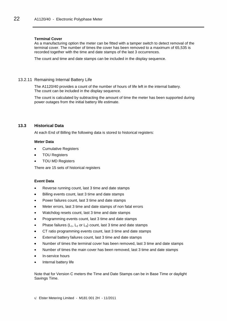
Terminal Cover As a manufacturing option the meter can be fitted with a tamper switch to detect removal of the terminal cover. The number of times the cover has been removed to a maximum of 65,535 is recorded together with the time and date stamps of the last 3 occurrences.
The count and time and date stamps can be included in the display sequence.
13.2.11 Remaining Internal Battery Life
The A1120/40 provides a count of the number of hours of life left in the internal battery. The count can be included in the display sequence.
The count is calculated by subtracting the amount of time the meter has been supported during power outages from the initial battery life estimate.
13.3 Historical Data
At each End of Billing the following data is stored to historical registers:
Meter Data
Cumulative Registers
TOU Registers
TOU MD Registers
There are 15 sets of historical registers
Event Data
Reverse running count, last 3 time and date stamps
Billing events count, last 3 time and date stamps
Power failures count, last 3 time and date stamps
Meter errors, last 3 time and date stamps of non fatal errors
Watchdog resets count, last 3 time and date stamps
Programming events count, last 3 time and date stamps
Phase failures (L1, L2 or L3) count, last 3 time and date stamps
CT ratio programming events count, last 3 time and date stamps
External battery failures count, last 3 time and date stamps
Number of times the terminal cover has been removed, last 3 time and date stamps
Number of times the main cover has been removed, last 3 time and date stamps
In-service hours
Internal battery life
Note that for Version C meters the Time and Date Stamps can be in Base Time or daylight Savings Time.

Operating & Maintenance Instructions 23
14 METER DISPLAY
14.1 Introduction
The A1120/40 meter is fitted with a high contrast liquid crystal display that can be viewed from a wide angle. The main display characters are 9.8mm high.
The display can be configured using the Power Master Unit to display data with English descriptors or OBIS (Object Identification System) format.
The Test Display with a description of the displayed legend (English or OBIS) is shown below.
English IdentifierOBIS Code
EnglishDescrip tion
Reverse Run
Phase Indicators
Chevrons Energy FlowDirection
Alarm
MultiplierX10, X100
Units of QuantityM, k, W, V, A, r, h
MeasurementRegister, Time,Date, Security Data
14.2 General
Display Resolution
The resolution of the display can be set at manufacture to 7, 6 or 5 digits. The decimal point indicator can be configured to be a point or a comma and set to 0, 1 or 2 places. kWh Wh mWh
Internal storage is :- 1 2 3 4 5 6 7 8 9 0 1 2 3. 4 5 6
The display is a window of this. e.g. 1 2 3 4 5 6 7 8 9 0 1 2 3. 4 5 6
Seven Digits Six Digits Five Digits
4 5 6 7 8 9 0
5 6 7 8 9 0. 1
6 7 8 9 0. 1 2
5 6 7 8 9 0
6 7 9 9 0. 1
7 8 9 0. 1 2
6 7 8 9 0
7 8 9 0. 1
8 9 0. 1 2
Units of Quantity and Multiplier
The Units of Quantity (Wh, kWh, MWh) and multiplier (x10, x100) displayed are selectable by the Power Master Unit and displayed in the top right corner of the display.
The display opposite shows kWh, x10.

24 A1120/40 - Electronic Polyphase Meter
Elster Metering Limited - M181 001 2H - 11/2011
14.3 Display Modes
The display has two modes of operation, Default Mode and Utility Mode. Up to 40 displays can be made available for each mode of operation.
14.3.1 Default Mode
The Default Mode can operate in two ways, Auto-cycle or single step.
Auto-cycle
At power up the segment test pattern is shown. This will remain displayed for a period of 3 seconds.
The display will then sequence through the programmed displays, remaining on each display item for one step duration time, called the Auto-cycle step duration (2-30 seconds).
3 seconds
Next display 2-30 seconds
Step
Step mode is entered by a single press of the Display Pushbutton. The first display in the autocycle sequence is displayed. Further presses of the pushbutton allow the consumer to step through the autocycle display items, and then through the single step display items.
The display will default to autocycle mode at a programmed time after the last press of the display pushbutton.
Display pushbutton press
Next display

Operating & Maintenance Instructions 25
14.3.2 Utility Mode
It is necessary to break the seal on the Reset Pushbutton to enter „Utility‟ mode. The mode is entered by pressing the Reset Pushbutton. „Utility‟ appears on the display. Single presses of the Display pushbutton will then step through the utility displays. The display will default to autocycle mode at a programmed time after the last press of the Display Pushbutton, or if the Reset Pushbutton is again pressed.
Short press Reset Pushbutton
Press Display Pushbutton
Next display
14.3.3 English Display
Chevrons & Identifiers
The chevrons on the display have the following meaning: Identifiers
Description
1 2 3 4 5 6 7
Import Security
Export
The display identifiers give a description of the main register displayed.
Examples of the display are shown in Figures 7.
A full list of displays is given in Figure 8.
14.3.4 OBIS Display
The OBIS code gives a description of the main register displayed. OBIS Code
Chevron 7 indicates the register is active.
Examples of displays and a full list of displays are given in Figures 7 and 8 respectively. Active
Chevron/Description
1 Import
2 Export
3 -
4 Security
5 -
6 -
7 -

26 A1120/40 - Electronic Polyphase Meter
Elster Metering Limited - M181 001 2H - 11/2011
14.4 Displayable Data
A full list of displayable data items is given in Figure 8. Items available will depend on the meter variant.
Segment Test Pattern
Cumulative Registers
Customer Defined Registers
Rising Demand Registers
TOU Maximum Demand
TOU Registers
Historical Registers
Security
Instrumentation
Phase Failure
CT Ratio
Tariff CRC
Meter Errors
Dial Test
For dial testing, the cumulative kWh and kvarh displays can be set to a higher resolution by using the Power Master Unit.
The resolution of the display can be configured to 0, 1, 2, 3 or 4 decimal places
Note: If the display is configured for Wh with no multiplier set, the maximum resolution of the display is 3 decimal places.
The meter will cease using dial test resolution when instructed by the Power Master Unit, or after a programmable number of power cycles.
Display Indicators
System Reverse Run Indicator
Phase Failure Indication
Per Phase Reverse Run Indication
Error/Alarm
Energy Direction Indicators
Communications Indication
When communications are taking place the following indicators are displayed in the top left corner of the display.
o Optical communication
r RS232 Communication Figure 7 shows examples of the display. The indicators can be disabled via the Power Master Unit.

Operating & Maintenance Instructions 27
15 USING THE PUSHBUTTONS
Two pushbuttons can be provided as an option. Their use is as follows:
Default Display Mode A short press of the display (right pushbutton) enters consumer display mode at the first display in the autocycle display sequence. Single presses of the display pushbutton allow the user to step through the consumer display sequence. The display will default to auto cycle mode at a programmed time after the last press of the consumer display pushbutton.
Utility Display Mode
A short press of the Reset (left pushbutton) enters the utility display mode at the first display in the utility sequence. Single presses of the display (right pushbutton) allow the user to step through the utility display sequence. The display will default to auto cycle mode at a programmed time after the last press of the display pushbutton, or if the Reset pushbutton is presses again.
Billing Reset
A Billing Reset can be initiated by holding both of the pushbuttons pressed for approximately 3 seconds. The billing reset pushbutton can be disabled by using the Power Master Unit.
As a further option, a message that a billing „reset‟ has been initiated can be displayed.
External Battery Support (Optional)
Pressing either pushbutton allows the displays to be read and optical communications to be established during power outages (See Appendix D).
16 COMMUNICATIONS
Communications with an A1120/40 can be established via the IEC 62056-21(formerly 1107) port
or via the optional RS232 Port. A symbol can be displayed in the top left corner of the display
which gives an indication of the type of communications currently taking place.
16.1 Optical Communications Port
A bi-directional infra red communications port is provided to allow reading of all stored data (measurement, diagnostic and current personality) and programming of "personality" data. Data Stream Mode (See Section 16.3) allows a fast method of retrieving all data from the meter.
The port is accessible through the front of the main cover and interfaces to a hand held unit or computer. In normal operation the port only operates when the meter is powered from the a.c. supply.
An optional battery (See Section 20) supports the port during power
outages. This facility is limited to reading data only.
The port can operate at baud rates of up to 9600.

28 A1120/40 - Electronic Polyphase Meter
Elster Metering Limited - M181 001 2H - 11/2011
16.2 Optional RS232 Port
An RJ11 connector provides RS232 communications. The port allows access to the same data as the optical port, using the same protocol. The port operates at speeds of up to 9600 baud. Data Stream Mode (See Section 16.3) allows a fast method of retrieving all data.
The RS232 port supports multi drop mode, allowing up to 10 meters (RS232) or 32 meters (RS485) to be accessed from a PC (See Appendix B).
16.2.1 Modem Power Supply
The RS232 port allows different modules to be added that can support different means of communications (PSTN, Ethernet, GSM etc).
An isolated internal d.c. supply to power the modem is provided via the RJ11 socket
Nominal Voltage: ≥+6V with mean load ≤500mA
The power is sufficient to support a GSM modem
16.2.2 Resetting the Power Supply
If a modem is installed which draws too much power from the meter, a transient reset occurs
and the modem power supply is disabled to prevent continuous resetting of the meter. On early
versions of A1120/40 meter only, the RS232 port may also be disabled. The power supply (and
RS232 port on early versions of the meter) can be re-enabled using the PMU via the IEC 1107
port or by using the following sequence:
Step to the „GSM (HAN) signal strength‟ display in the General Display section of the meter
Press the display and utility pushbuttons together for several seconds until „PSU On‟ is
displayed
If the meter generates another reset, an alternative modem should be fitted and the power
supply re-enabled as above.
16.2.3 Signal Strength
The HAN and WAN Signal strength can be shown on the display.
16.3 Data Stream Mode
Data stream mode allows fast reading of all metering data (90 days of 30 minute, one channel data in 30 seconds). To achieve this, the meter and modem device must be configured to 8 bits, no parity, 1 stop bit (Selectable via the Power Master Unit).

Operating & Maintenance Instructions 29
17 PROGRAMMING THE METER
The meter can be programmed via the optical port or via the RS232 port. The optical port can be connected either directly to a PC (IBM compatible) or to a Hand Held Unit. In both cases an IEC 62056-21 (formerly 1107) Probe is required.
Information for the meter is first prepared on forms within the Power Master Unit Software (Refer to Master Unit Software M181 001 3).
The meter does not check to ensure that reprogramming has been completed, therefore at the end of a reprogramming session all data should be read back to confirm the meter is programmed correctly.
If communications fail during programming a failure message is displayed.
Each time the meter is reprogrammed, the programming counter is incremented and the time and date of the event is recorded. The user who created the scheme in the PMU is recorded.
Note: The programming counter does not increment when a 'Set time' or 'Time and date adjustment' only is programmed to the meter.
18 REAL TIME CLOCK AND CALENDAR
The clock uses the notation 00:00 to 23:59. The calendar automatically caters for leap years.
Note: - For time stamps 00:00 indicates the start of the day and 24:00 the end of the day.
The time base for the clock is a programmable option. It can be derived from either the a.c. supply frequency or from a crystal controlled oscillator.
When the clock is synchronised to the mains frequency, it maintains synchronisation for variations of up to +/- 5% of nominal mains frequency. Outside these limits the meter switches to the crystal oscillator and then switches back to mains when the frequency is back within limits.
Crystal calibration achieves an internal accuracy of better than 0.5 of a second per day at reference temperature. In the event of a supply failure a backup battery supports the crystal oscillator, which maintains timekeeping.
There are two methods of adjusting the meter clock:
1. The time and date of the clock may be set via the IEC 62056-21 optical port or RS232 communications port (if fitted) provided the correct (level 2 or higher) password is used.
2. If a request for a small adjustment (-7.5 minutes to +7.5 minutes) to the current setting is made (with appropriate password), this adjustment will be applied by shortening or lengthening subsequent demand periods by 5 seconds until the whole of the adjustment has been achieved.

30 A1120/40 - Electronic Polyphase Meter
Elster Metering Limited - M181 001 2H - 11/2011
19 BATTERY BACK-UP
The A1120/40 has an internal battery that supports the clock and calendar.
An optional external battery that supports the reading of meter data and display facilities during power outages can be provided.
19.1 Internal Battery
In the event of an a.c. failure, an internal battery (a Lithium „coin‟ cell) supports the real time clock.
The battery is soldered onto the printed circuit board.
The meter can be programmed to initiate one of the following courses of action should the supply fail and the battery become exhausted. When the supply returns: -
a. Freeze the TOU registers and increment the total cumulative registers only b. Assume the last known time and continue to use the TOU registers
See Section 29 for battery disposal.
19.1.1 Internal Battery Monitoring
The battery provides support for the life of the meter. The following functions are provided on the Battery Monitor: -
Elapsed Time - The total amount of battery support time is monitored. The elapsed time counter decrements to represent the use/shelf life of the battery.
Remaining Time - The remaining battery life is calculated by subtracting the elapsed time from the expected time. The remaining life may be read via the optical or RS232 communications port and its value optionally included in the display sequence.
If the remaining time falls to zero, a „flag‟ is set which can be read by via the optical port or RS232 port.
Failed Battery - The occurrence of total battery fail is monitored each time the meter is energised. A flag is set and the time and date recorded when the meter last powered down.

Operating & Maintenance Instructions 31
20 MODULE/BATTERY CARRIER
A Special housing can be supplied as an option for a Module or External Battery. Molex Connector
20.1 Communications Module
Simple installation
Snap in position
Sealable (under the terminal cover)
Connects to the meter via a 'RJ11' connector
Refer to Chapter 3 (M181 001 3) Communications Modules
20.2 External Battery Module
Simple installation
Snap in position
Sealable (under the terminal cover)
Connects to the meter via a 'Molex' connector
Refer to Appendix D, External Battery Module
21 OUTPUT
An optional output can be provided. This output can be set at manufacture to one of the following options:
SO output, floating, customer configurable pulse duration/value
SO output, floating, replicating the kWh LED
SO output, floating, replicating the kvarh LED
100mA relay output, floating, customer configurable pulse duration/value
100mA relay output, floating, replicating the kWh LED
100mA relay output, floating, replicating the kvarh LED
300mA relay output, floating, customer configurable pulse duration/value
The outputs have the following characteristics:
SO Output 100 mA Relay Output 300mA Relay Output
Maximum voltage (Umax) 27V d.c. 230V a.c or d.c 230V a.c
Maximum current in On-state 27 mA 100mA 300mA
Minimum current in On-state 10 mA
Maximum current in Off-state 2 mA
The output is connected using two 3.2mm diameter terminals (See Figure 5).
The pulse output meets the requirements of IEC 62053-31.
RJ11 Connector

32 A1120/40 - Electronic Polyphase Meter
Elster Metering Limited - M181 001 2H - 11/2011
WARNING
See Warning in Section 26.6 regarding additional protection for circuits connected to the auxiliary terminals.
21.1 Customer Configurable Auxiliary Output (SO and Relay)
Retransmit
The customer configurable auxiliary output can be sourced (using the Power Master Unit) to
transmit pulses from one of the following registers:
Cumulative registers (Import or export Wh - Q1, Q2, Q3 or Q4 - VAh 1 or VAh 2)
Customer defined registers (Register 1 or Register 2)
The pulse value and width can be configured as follows:
Pulse value 1, 2, 4, 5, 10, 20, 40, 50, 100, 200, 250
Pulse width (ms) 10, 20, 30, 40, 50, 60, 80, 100, 120, 160, 200, 250
High Impedance
Low Impedance
Energy = Pulseconsumed ) value
Pulse width
Caution
Care should be taken in selecting the combination of pulse width and pulses/unit.
Avoid combinations that may give insufficient spacing between pulses at maximum load.
To ensure correct operation a maximum of 10 pulses/sec should not be exceeded.
When the meter is in anti-creep mode the output does not pulse.
Rate Indication
The output can be sourced (using the Power Master Unit) to provide indication of an active rate.
The output becomes low impedance if any one of a selected combination of TOU or MD TOU tariffs is activate.

Operating & Maintenance Instructions 33
21.2 Test Indication (Manufacturing option)
The output can be configured at manufacture to generate pulses that replicate the kWh LED or the kvarh LED.
This option is desirable if meter accuracy verification must be performed without using optical pickups. When configured in this way the auxiliary output pulse width and LED pulse width are the same (approximately 6 ms).
22 ADDITIONAL VOLTAGE TERMINALS
As an option the A1120/40 can be supplied with additional terminals that allow external
equipment to be powered from the meter (See Figure 5).
WARNING
Connections made to these terminals will only be protected by the installation‟s main fuse cut-out.
The installer must ensure that additional local protection is provided for any circuits connected to these terminals.
23 LOAD PROFILE RECORDING (A1140)
4 Demand Values(kW, kvar, kVA,
Customer Defined)
Demand Period End
Typical Load Profile Recording
Readings
Readings
Power Master Unit
ProprietarySoftware
Channels Days 1 300 2 300 3 265 4 205
(30 minute integration period)
The A1140 can be programmed to record up to four values from any of the rising demand registers at the end of each integration period. Up to 300 days of 30 minute data can be stored for a single channel. The number of day's storage is reduced if Instrumentation Profiling is configured, the Number of Channels stored is increased or the Integration Period is reduced.
Integration period - 1, 2, 3, 4, 5, 6, 10, 15, 20, 30, 60 minutes. Common with the demand period.
Load profile data is stored with reference to either base time or daylight saving time.
Base Time - Daylight savings have no effect on the demand period and 48 periods are stored (assuming 30 minute integration period).
Daylight savings time - When the clock advances, 46 periods will be stored. When the clock retards, 50 periods will be stored (assuming 30 minute integration period).

34 A1120/40 - Electronic Polyphase Meter
Elster Metering Limited - M181 001 2H - 11/2011
Status information is also stored with each integration:
Load profile event indication with time and date stamps – Power up, Power down, Time change, Configuration change, New day, Daylight savings, Forced end of demand.
Load profile status indication per period – Transient reset, Time synchronisation, Data change, CT ratio change, Internal battery failure, Reverse run, Phase failure (one or more phases).
When storage is full, new data overwrites the oldest stored data.
Using Data Stream Mode (9600 baud rate), 90 days of single channel, 30 minute demand period data can be read in less than 30 seconds.
Two methods of reading load profile data are provided:
Number of day‟s data up to and including the current day
From day x up to and including day y.
Load profiles can be transferred to the Power Master Unit and viewed in Readings.
24 INSTRUMENTATION
The A1120/40 calculates the following instrumentation values:
Volts (Phase A, B, C)
Current (Phase A, B, C)
Watts (Phase A, B, C, System)
Phase Angle (Phase A, B, C)
Phase Rotation (Phase A, B, C)
Power Factor (Phase A, B, C, System)
Frequency (Phase A, B, C)
Instrumentation values can be included in the display sequence.

Operating & Maintenance Instructions 35
25 TECHNICAL DATA
Current: Standard Range (direct connected)
Extended Range (direct connected)
Standard Range (CT operated)
Extended Range (CT operated)
20 - 100A, 10 - 100A
5 - 100A
1 - 2A, 5 - 10A
1 - 10A
Frequency
Reference Voltage
Voltage Operating range
System Connection - 2 element meter
- 3 element meter
50 or 60Hz
220V - 240V (L – N)
220V - 240V (L – L)
105V - 127V (L – N)
105V - 127V (L – L)
±20%
3 phase 3 wire
3 phase 4 wire
2 phases of 3 phase 4 wire
2 phase 3 wire
1 phase 3 wire
1 phase 2 wire
Short Circuit Current
Burden of Voltage Circuits 230V
Burden of Current Circuits (10 – 100A meter)
Burden of CT Operated Meters
Insulation
Impulse Withstand
30 Imax
0.8W, 1.3VA
4VA @ 100A/phase [max]
0.22VA per phase
4kV RMS
12kV 1.2/50s 40 ohm source
Display 9.8mm characters, high contrast, wide viewing angle
Meter Constant (pulsing LED output) 1,000 p/kWh (kvarh) Direct connected
10,000p/kWh (kvarh) CT Operated
Approximately 6ms Pulse width
Pulse Output Specification
SO Output (12 kV isolation)
100mA Relay Output (12 kV isolation)
300mA Relay Output (12 kV isolation)
27V d.c. 27 mA, IEC 62053-31 (Transistor Output)
230V a.c or d.c, 100mA
230V a.c 300mA
Product Life
Certified Life
15 years
10 years
Temperature
Humidity
Operational range: -25 C to +65 C
Storage Range: -25 C to +85 C
Condensing (See note below)
Annual Mean 75% (95% for 30 days spread over one year)
Maximum Dimensions
Weight
233mm (High) x 174 mm (Wide) x 50mm (Deep)
904 grams
Accuracy Class kWh
kWh
kvar
EN 62053-21/22 - Class 0.5s, 1 or 2
EC Directive 2004/22/EC (MID) - Class A, B or C
EN 62053-23 - Class 2 or Class 3
Case DIN 43857 Part 2 and Part 4 (except for top fixing centre)
IP53 to IEC 60529:1989
EMC Directive 89/336/EEC
Terminals Main
Auxiliary
8.2mm bores, M6 Terminal Screws – max torque 2.8 N m
9.0mm bores, M6 Terminal Screws – max torque 2.8 N m
9.5mm bores, M6 Terminal Screws – max torque 2.8 N m
3.2 mm bores, M3 Terminal Screws – max torque 0.45 N
Note: Sample meters have successfully passed the “Damp heat cyclic” test given in section 6.3.4 of EN50470-1. However, for maximum operational life, it is recommended that installation sites are chosen where condensation is unlikely to occur.
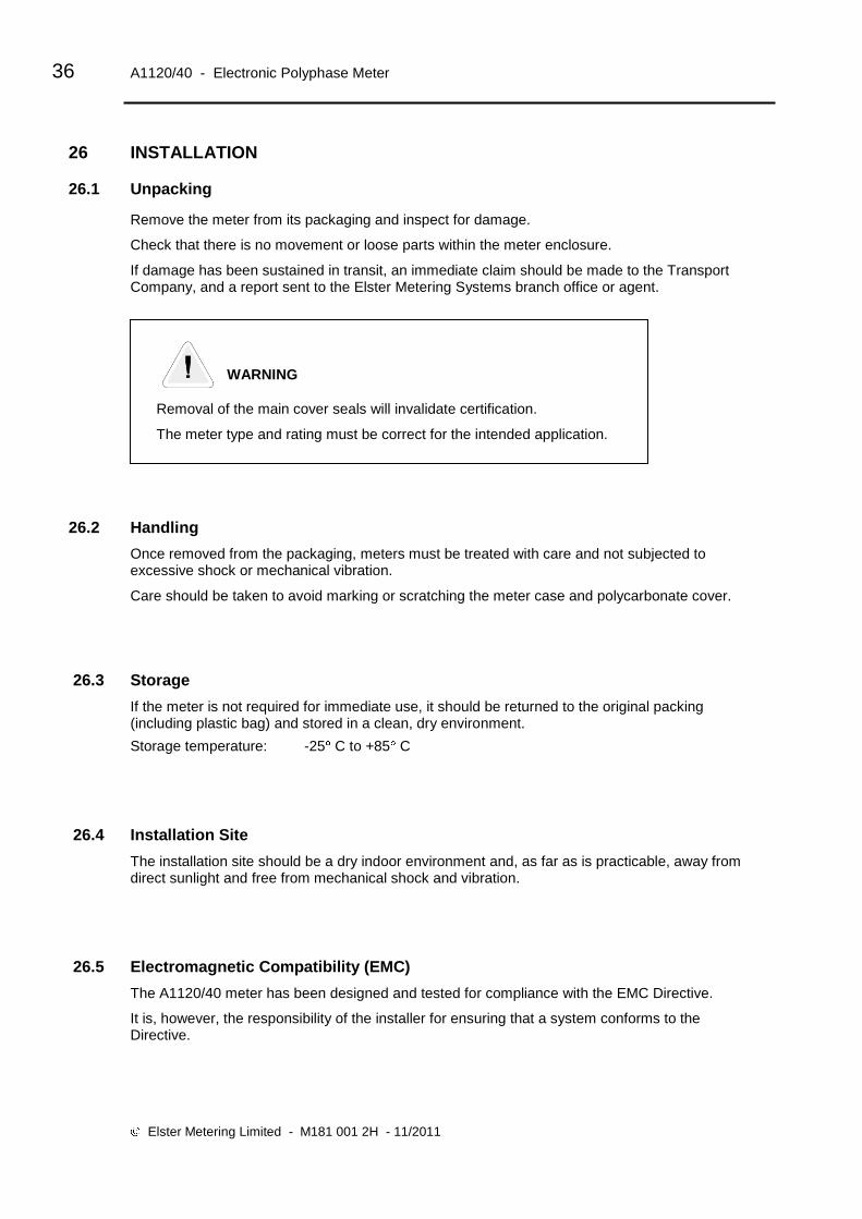
36 A1120/40 - Electronic Polyphase Meter
Elster Metering Limited - M181 001 2H - 11/2011
26 INSTALLATION
26.1 Unpacking
Remove the meter from its packaging and inspect for damage.
Check that there is no movement or loose parts within the meter enclosure.
If damage has been sustained in transit, an immediate claim should be made to the Transport Company, and a report sent to the Elster Metering Systems branch office or agent.
WARNING
Removal of the main cover seals will invalidate certification.
The meter type and rating must be correct for the intended application.
26.2 Handling
Once removed from the packaging, meters must be treated with care and not subjected to excessive shock or mechanical vibration.
Care should be taken to avoid marking or scratching the meter case and polycarbonate cover.
26.3 Storage
If the meter is not required for immediate use, it should be returned to the original packing (including plastic bag) and stored in a clean, dry environment.
Storage temperature: -25 C to +85 C
26.4 Installation Site
The installation site should be a dry indoor environment and, as far as is practicable, away from direct sunlight and free from mechanical shock and vibration.
26.5 Electromagnetic Compatibility (EMC)
The A1120/40 meter has been designed and tested for compliance with the EMC Directive.
It is, however, the responsibility of the installer for ensuring that a system conforms to the Directive.
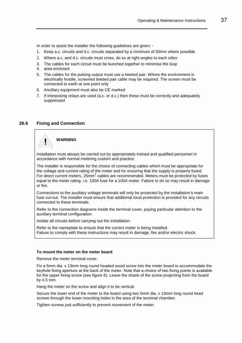
Operating & Maintenance Instructions 37
In order to assist the installer the following guidelines are given: -
1. Keep a.c. circuits and d.c. circuits separated by a minimum of 50mm where possible
2. Where a.c. and d.c. circuits must cross, do so at right angles to each other
3. The cables for each circuit must be bunched together to minimise the loop 4. area enclosed
5. The cables for the pulsing output must use a twisted pair. Where the environment is electrically hostile, screened twisted pair cable may be required. The screen must be connected to earth at one point only
6. Ancillary equipment must also be CE marked
7. If interposing relays are used (a.c. or d.c.) then these must be correctly and adequately suppressed
26.6 Fixing and Connection
WARNING
Installation must always be carried out by appropriately trained and qualified personnel in accordance with normal metering custom and practice.
The installer is responsible for the choice of connecting cables which must be appropriate for
the voltage and current rating of the meter and for ensuring that the supply is properly fused.
For direct current meters, 25mm2 cables are recommended. Meters must be protected by fuses
equal to the meter rating. i.e. 100A fuse for a 100A meter. Failure to do so may result in damage
or fire.
Connections to the auxiliary voltage terminals will only be protected by the installation‟s main fuse cut-out. The installer must ensure that additional local protection is provided for any circuits connected to these terminals.
Refer to the connection diagrams inside the terminal cover, paying particular attention to the auxiliary terminal configuration.
Isolate all circuits before carrying out the installation.
Refer to the nameplate to ensure that the correct meter is being installed.
Failure to comply with these instructions may result in damage, fire and/or electric shock.
To mount the meter on the meter board
Remove the meter terminal cover.
Fix a 5mm dia. x 13mm long round headed wood screw into the meter board to accommodate the keyhole fixing aperture at the back of the meter. Note that a choice of two fixing points is available for the upper fixing screw (see figure 6). Leave the shank of the screw projecting from the board by 4.5 mm.
Hang the meter on the screw and align it to be vertical.
Secure the lower end of the meter to the board using two 5mm dia. x 13mm long round head screws through the lower mounting holes in the area of the terminal chamber.
Tighten screws just sufficiently to prevent movement of the meter.

38 A1120/40 - Electronic Polyphase Meter
Elster Metering Limited - M181 001 2H - 11/2011
WARNING
Do not over-tighten the screws or the meter base may be damaged.
For connecting to the large diameter terminals, strip back the cable insulation by 26mm.
Fully insert cables into the terminals so that the insulation butts up into the counter-sunk recesses in the bottom face of the terminal block.
Using a Number 2 Phillips or flat blade screwdriver, tighten the M6 terminal screws to a torque of between 2.2N m (minimum), 2.8N m (maximum).
Auxiliary terminal connections should be completed with appropriately sized cable. The M3 terminal screws should be tightened using a Number 1 Phillips or flat blade screwdriver to a maximum torque of 0.45N m.
Where connections are taken from the auxiliary voltage terminals, appropriate fuses should be incorporated to protect these circuits.
If a battery (for read without power) is installed in the module housing, the battery must be connected before mains supplies are energised.
It is also recommended that connections to the meter‟s RJ11 connector are made with the meter supplies isolated.
27 COMMISSIONING
WARNING
Commissioning must only be carried out by appropriately trained and qualified personnel.
Check that the supply rating on the meter nameplate corresponds to the system rating.
Removal of the meter cover seals will invalidate certification.
With the system de-energised, check the cable connections are secure and correct to the wiring diagram fitted under the terminal cover
Refit and seal the terminal cover. Energise and load the system
At power-up, ensure all segments of the LCD show in the test pattern
Check that the display is cycling through the display sequence
Check that the LED test indicators are illuminated or flashing
Check the operation of the pulse output (if fitted)
Check operation of the RS232 port (if fitted)
Carry out load checks as necessary

Operating & Maintenance Instructions 39
28 MAINTENANCE
No maintenance is necessary during the meter's normal working life.
29 DISPOSAL AND RECYCLING
Liquid Crystal Display
Liquid crystals are toxic. If a display is damaged, avoid contact with the liquid. If the liquid
makes contact with the skin it must be washed off immediately with water. Seek medical advice.
Recycling Materials
The following meter materials are recyclable: polycarbonates, metals and printed circuit board
(see Safety Warning in Section 2).
Major plastic parts are marked with recycling information. On the disposal of a meter, every endeavour should be made to comply with local environmental legislation regarding recovering materials and waste disposal.
Batteries
If the main cover is removed from the meter then a Lithium manganese dioxide battery will be
exposed.
This battery is completely safe under normal conditions. However, it must never be
disassembled, heated above 100 C, incinerated, nor have the contents exposed to water.
Fire, explosion or severe burns may result if these instructions are disregarded.
In the interests of safety, environmental protection and possible legislation, Lithium batteries
require careful disposal.
Before arranging for the disposal of these cells, users should satisfy themselves that the
proposed means of disposal is both safe and compliant with local legislation requirements.
Elster Metering Systems would like to draw the user's attention to the International Standard for
Lithium Batteries - IEC 60086-4. - which gives further information about the handling, storage,
transport and disposal of Lithium cells.
The user should contact Elster Metering Systems should difficulties arise in arranging proper
disposal. They will if practical, help the user identify safe disposal means.
An optional battery may be housed in a module housing attached to the meter. The battery is a non re-chargeable, alkaline zinc manganese dioxide, PP3 size. Where local legislation places restraint on the disposal of this type of battery, the requirements of that legislation should be obeyed.

40 A1120/40 - Electronic Polyphase Meter
Elster Metering Limited - M181 001 2H - 11/2011
POLYPHASE (A1120/A1140) MODEL CODE
Vref Ib Imax MODEL
L-L L-N TYPE (nameplate)
example: L M 3 A A B N N B B B N N B - A N
PRODUCT/TERMINATION
Polyphase, BS/DIN termination L M
SERVICE TYPE
3Ph 4W for use on: 3
3Ph 3W 2
CURRENT RANGE
Direct Connected 20A – * (* is any multiple of Ib up to 100A maximum) A
Direct Connected 10A – * (* is any multiple of Ib up to 100A maximum) B
Direct Connected 5A – * (* is any multiple of Ib up to 100A maximum) C
CT Operated 1A – 2A L
CT Operated 5A – 10A M
CT Operated 1A – 10A N
Direct Connected (10A - 100A) -40 to 70 C operation P
VOLTAGE
220 - 240V (L - N) (See note 2 for Ref voltage ranges) A
220 - 240V (L - L) (See note 2 for Ref voltage ranges) (LM2****** variants only) B
105 - 127V (L - N) (See note 2 for Ref voltage ranges) Not OFGEM Approved/MID Approved C
105 - 127V (L - L) (See note 2 for Ref voltage ranges) (LM2****** variants only) Not OFGEM Approved/MID Approved D
ACCURACY CLASS
50Hz Cl.0.5 kWh, Cl.2 kvarh (IEC 62053-22, 23 see note 1) Cl.C kWh, (EN 50470 - 3) Note:- Class 0.5 or Class C is applicable to 5-6/10A "3 Ph 4W and 3 Ph 4W variant only"
A
50 Hz Cl.1 kWh, Cl.2 kvarh (IEC 62053-21, 23 see note 1) Cl.B kWh, (EN50470-3) B
50 Hz Cl.2 kWh, Cl.3 kvarh (IEC 62053-21, 23 see note 1) Cl.BA kWh, (EN50470-3) C
60 Hz Cl.1 kWh, Cl.2 kvarh (IEC 62053-21, 23 see note 1) Not OFGEM Approved/MID Approved E
60 Hz Cl.2 kWh, Cl.3 kvarh (IEC 62053-21, 23 see note 1) Not OFGEM Approved/MID Approved F
HARDWARE - SWITCHES
No tamper detect switches N
Two tamper detect switches B
Terminal cover tamper detect switch and CT ratio programming protection switch C
HARDWARE - BUTTONS
No buttons N
Two buttons B
Backlit LCD with no buttons C
Backlit LCD with twom buttons D
HARDWARE - BATTERY
No external battery connection N
External Battery connection. Note! External battery module cannot be fitted when an RS232 comms module is fitted B
Supercapacitor/External battery/RS485 module connection C
OPERATIONAL MODES
Import kWh only B
Import kWh, Q1 and Q4 kvarh C
Import kWh, Q1, Q2, Q3, Q4 kvarh and Imp kVAh D
Imp/Exp kWh E
Imp/Exp kWh, Q1, Q2, Q3, and Q4 kvarh F
Imp/Exp kWh and Imp/Exp kVAh G
Imp/Exp kWh, Q1, Q2, Q3, Q4 kvarh and Imp/Exp kVAh H
Import kWh only (Power Flow Insensitive) J
Import kWh, Q1 and Q4 kvarh (Power Flow Insensitive) K
Import kWh, Q1, Q2, Q3, Q4 kvarh and Imp kVAh (Power Flow Insensitive) L
Import kWh only (Theft Resistant Measurement) R
Import kWh, Q1 and Q4 kvarh (Theft Resistant Measurement) S
Import kWh, Q1, Q2, Q3, Q4 kvarh and Imp kVAh (Theft Resistant Measurement) T
TARIFFS
A1120 Multi Rate B
A1140 Multi Rate (with load profile) C
A1120 Multi Rate with password protected register zeroing and zero level time shift D
A1140 (with load profile) Multi Rate with password protected register zeroing and zero level time shift E
AUXILIARY OUTPUT
No Output N
SO output, floating, 2 aux terminals. 12 kV isolation (Configurable pulse duration/value) 27V DA only P
SO output, floating, 2 aux terminals. 12 kV isolation, replicating centre LED (kWh) 27V DA only A
SO output, floating, 2 aux terminals. 12 kV isolation, replicating left hand LED (kvarh) 27V DA only R
Relay output, floating, 2 aux terminals. 12 kV isolation (Configurable pulse duration/value) 230V AC, DC S
Relay output, floating, 2 aux terminals. 12 kV isolation, replicating centre LED (kWh) 230V AC, DC D
Relay output, floating, 2 aux terminals. 12 kV isolation, replicating left hand LED (kvarh) 230V AC, DC U
300mA Relay output, floating, 2 aux terminals, 12kV isolation, indicating tariff/MD state, 230V a.c only T
COMMUNICATIONS
No Serial Comms N
RS232 serial Comms Note! RS232 Comms module cannot be fitted when an external battery module is fitted R
OTHER OPTIONS
Standard (Extended) Terminal cover B
Standard (Extended) Terminal cover with cut-out C
Standard (Extended) Terminal plus 9.0mm main terminal bores D
Short Terminal Cover E
Standard (Extended) Terminal cover with additional voltage terminals F
Standard (Extended) Terminal cover with cut-out and additional voltage terminals G
Standard (Extended) Terminal cover plus 9.0 mm mail terminal bores and additional voltage terminals H
Standard (Extended) Terminal cover plus 9.5 mm main terminal bores J
Standard (Extended) Terminal cover and main cover with voltage disconnect protection K
Figure 1 - Model Code

Operating & Maintenance Instructions 41
Standard (Extended) Terminal cover with slotted head screws L
Standard (Extended) Terminal cover with cut-out and slotted head screws M
Short terminal cover with slotted head screws P Standard (Extended) Terminal cover with cut-out plus 9.0 mm mail terminal bores Q Standard (Extended) Terminal cover with cut-out and main cover with voltage disconnect protection R Feature Set
8 TOU Registers, 4 MD Registers, 15 Historical Registers, DSM - see Note 4 for scheme compatibility - A
8 TOU Registers, 4 MD Registers, 15 Historical Registers, DSM, DLS time stamps and 12 external registers - Note! All new customers from November 2007 - see Note 4 for scheme compatibility
- C
8 TOU Registers, 4 MD Registers, 15 Historical Registers, DSM, DLS Time stamps, 12 External Registers, Daily Billing and Per Phase Registration. see Note 4 for scheme compatibility. Note This feature set requires the use of PMU version 3.1.4216 or later.
F
8 TOU Registers, 4 MD Registers, 15 Historical Registers, DSM, DLS Time stamps, 12 External Registers - Note! Register zeroing by use of "Register Zeroing Tool" is NOT available in this option. See Note 4 for scheme compatibility.
G
8 TOU Registers, 4 MD Registers, 15 Historical Registers, DSM, DLS Time stamps, 12 External Registers and tamper flag in Load Profile. See Note 4 for scheme compatibility.
H
Revision Suffix
Firmware 2-01178-Q (Version A only). Enhanced GPRS and COP 10 Q
Firmware 2-01322-K (Version C and H) Enhanced GPRS and COP 10 L
Firmware 2-01340-B (Version F) Daily Billing and per phase registration (Note: requires PMU version 3.51.4216 or later) D
Firmware 2-01345-A (Version G) Enhanced GPRS & COP 10. No register zeroing Z
SPECIAL ADDITIONS FIRMWARE
None N
Additional Firmware Function for ESCOM only (Phase angle definition as A1700 A
SPECIAL ADDITIONS HARDWARE
NONE N
Note 1: CURRENT RATINGS - IEC/EN 62052-11 defines only Basic, Reference and Maximum currents as follows:
Basic Current (Ib) Direct Connected Standard values: 5, 10, 15, 20, 30, 40, 50A Exceptional values: 80A.
Reference Current (In) CT Operated Standard values: 1, 2, 5A Exceptional values: 1.5, 2.5A
Direct Connected Maximum current (Imax) shall preferably be an integral multiple of Ib.
Direct Connected A1120/A1140 meters may have Imax values up to a maximum of 100A
CT Operated shall have maximum currents of 1.2 In, 1.5 In and 2 In
CT Operated A1120/A1140 meters may be:
1 - 2A (suitable for use as 1 - 1.2A, 1 - 1.5A, or 1 - 2A) 5 - 10A (suitable for use as 5 - 6A, 5 - 7.5A, or 5 - 10A) 1 - 10A (suitable for use with any of the above 6 ratings)
EN 50470-1 (MID) defines basic values or Itr from which Imin, Iref and Imax can be derived Basic values of Itr Direct Connected 0.5, 1, 1.5, 2A Basic values of Itr CT Operated 0.05, 0.1, 0.25
Imin, Iref and Imax have been chosen so that the following relationships are met Direct Connected, Class A Imin < 0.5 x Itr Iref = 10 x Itr Imax > 50 x Itr CT Operated, Class A Imin < 0.4 x Itr In = 20 x Itr Imax > 1.2 x In Direct Connected, Class B Imin < 0.5 x Itr Iref = 10 x Itr Imax > 50 x Itr CT Operated, Class B Imin < 0.2 x Itr In = 20 x Itr Imax > 1.2 x In
Note 2: VOLTAGE RATINGS - Of the values IEC/EN 62052-11 defines for reference voltages, the following may be accepted
Ref Voltages for meters not connected through current transformers
Std values 120, 230, 400V Exceptional values 100, 127, 200, 220, 240, 380, 415V
EN 50470- 1 (MID) defines for reference voltages, the following standards and exceptional values
Ref Voltages for Direct Connected
Std values 230/400V Exceptional values 220/380V, 240/415V
Meters with marked currents and voltages other than the above values CANNOT be provided when the nameplate shows the IEC/EN Standard Number.
If a valid requirement exists for meters with marked values within the acceptable ranges, but not listed above, specific arrangements to provide nameplates not showing the IEC/EN standard must be made. Note 3: TEST INDICATOR OUTPUT VALUES - The following values are to be used for the Test Indicator LED outputs:
Direct Connected: 1,000 p/kWh (kvarh) CT Operated: 10,000 p/kWh (kvarh)
Note 4: SCHEME COMPATIBILITY - Schemes generated for VERSION 'A' meters are not compatible with VERSION 'C' meters
Note 5: SPECIAL ADDITIONS - Early issues of this code used the final (16th) digit for SPECIAL ADDITIONS and an 'A' in this
position indicates "with additional voltage terminals".
Figure 1 - Model Code (Continued)

42 A1120/40 - Electronic Polyphase Meter
Elster Metering Limited - M181 001 2H - 11/2011
1. Reset Pushbutton 5. Display
2. Display Pushbutton 6. Nameplate
7. IEC 62056-21 Port
3. kvarh pulse LED
4. kWh pulse LED
1 Reset Pushbutton (See Section 15)
2 Display Pushbutton (See Section 15)
3 kvarh Pulse Indicator (See Section 9)
4 kWh Pulse Indicator (See Section 9)
5 Display (See Section 14)
6 Nameplate (See Figure 3)
7 IEC 62056-21 Port (See Section 16)
Module Carrier (Fits under the terminal cover)
Figure 2 – A1120/40 Meter

Operating & Maintenance Instructions 43
Figure 3 - Typical Nameplate

44 A1120/40 - Electronic Polyphase Meter
Elster Metering Limited - M181 001 2H - 11/2011
Figure 4 - Load Curves

Operating & Maintenance Instructions 45
Terminal Block (3 phase 4 wire shown)
Voltage connections Voltage Links shown in open position Main cover removal or CT ratio programming switch on a CT Meter. (whole current meters only) Terminal cover removal switch Optional additional
Voltage terminal on direct connected meter
Molex connector
to connect external battery
1 2 3 4 5 6 7 8 9 10 12 20 21 Element 1 Element 2 Element 3 Neutral Auxiliary Terminals RJ 11
RJ 11 and Auxiliary Terminals
Auxiliary Terminals
RJ11 Socket
6 5 4 3 2 1
Terminal & RJ11 Numbering
Terminal RJ11
1 2 3
Element 1 - Line in - Voltage terminal - Line out
1 2 3 4 5 6
Rx (Input) Tx (Output) Rx (Input) No Connection Zero Volts Modem Power Supply (+) Output
4 5 6
Element 2 - Line In - Voltage Terminal - Line Out
7 8 9
Element 3 - Line In - Voltage Terminal
- Line Out
10 12
Neutral In Neutral Out
Auxiliary 20 positive 21 negative
See Warning in Section 22 regarding protection for additional voltage terminals.
Figure 5 - Terminal Arrangements

46 A1120/40 - Electronic Polyphase Meter
Elster Metering Limited - M181 001 2H - 11/2011
TO
LO
ADA
B
NC
+-
20 21
A
BC
JL 3
013 3
12B
LM3 ***
RxTx0V+V
3 phase 4 wire, CT operated
TO
LO
ADA
B
NC
+-
20 21
A
BC
JL 3
013 3
11B
LM3 ***
RxTx0V+V
3 phase 4 wire, Direct connected
Note: These diagrams are examples only.
WARNING
Meters must be connected according to the diagram fitted under the meter terminal cover.
Figure 5A – Terminal Configurations

Operating & Maintenance Instructions 47
Back View Side View
171.5mm 49mm
139mm
121mm
233mm
150mm
110mm
Terminal Cover with Cut-out Short Terminal Cover
Figure 6 – Dimensions, Fixing Centres

48 A1120/40 - Electronic Polyphase Meter
Elster Metering Limited - M181 001 2H - 11/2011
English Displays OBIS Displays
Segment Test
Cumulative
Customer Defined (1-2)
Rising Demand (Export)
Maximum Demand (1-4)
Maximum Demand (1-4) Date Time
Cumulative Maximum Demand (1-4)
Time of Use (1-8)
Figure 7 - A1120/40 Displays
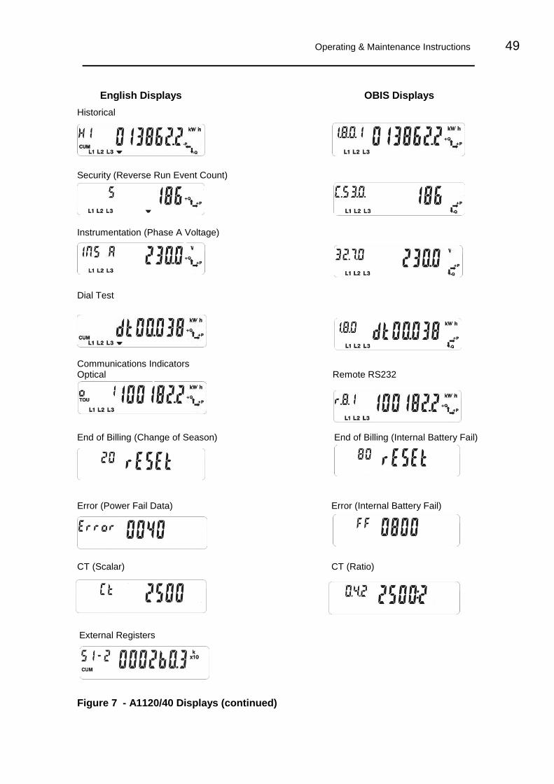
Operating & Maintenance Instructions 49
English Displays OBIS Displays
Historical
Security (Reverse Run Event Count)
Instrumentation (Phase A Voltage)
Dial Test
Communications Indicators Optical Remote RS232
End of Billing (Change of Season) End of Billing (Internal Battery Fail)
Error (Power Fail Data) Error (Internal Battery Fail)
CT (Scalar) CT (Ratio)
External Registers
Figure 7 - A1120/40 Displays (continued)

50 A1120/40 - Electronic Polyphase Meter
Elster Metering Limited - M181 001 2H - 11/2011
Description Units OBIS Display Code English Display
Note 1** Identifier Chevron Index
Segment Test - - - - -
Current Time - 0.9.1 - - -
Current Date - 0.9.2 - - -
Cumulative
Total Import kWh kWh 1.8.0 CUM 1 -
Total Export kWh kWh 2.8.0 CUM 2 -
Q1 kvarh kvarh 5.8.0 CUM - 1
Q2 kvarh kvarh 6.8.0 CUM - 2
Q3 kvarh kvarh 7.8.0 CUM - 3
Q4 kvarh kvarh 8.8.0 CUM - 4
kVAh 1 kVAh D.8.0 CUM - -
kVAh 2 kVAh E.8.0 CUM - -
Total Import kWh Phase A * kW 21.8.0 CUM 1 A
kWh Phase B * kW 41.8.0 CUM 1 B
kWh Phase C * kW 61.8.0 CUM 1 C
Total Export kWh Phase A * kW 21.8.0 CUM 2 A
kWh Phase B * kW 41.8.0 CUM 2 B
kWh Phase C * kW 61.8.0 CUM 2 C
Customer Defined 1 ** A.8.0 CUM - Cd 1
Customer Defined 2 ** B.8.0 CUM - Cd 2
Rising Demand
Total Import kW kW 1.4.0 DEM 1 -
Total Export kW kW 2.4.0 DEM 2 -
Q1 kvar kvar 5.4.0 DEM - 1
Q2 kvar kvar 6.4.0 DEM - 2
Q3 kvar kvar 7.4.0 DEM - 3
Q4 kvar kvar 8.4.0 DEM - 4
kVA 1 kVA D.4.0 DEM - -
kVA 2 kVA E.4.0 DEM - -
Total Import kWh Phase A * kW 21.4.0 DEM 1 A
kWh Phase B * kW 41.4.0 DEM 1 B
kWh Phase C * kW 61.4.0 DEM 1 C
Total Export kWh Phase A * kW 21.4.0 DEM 2 A
kWh Phase B * kW 41.4.0 DEM 2 B
kWh Phase C * kW 61.4.0 DEM 2 C
CD 1 ** A.4.0 DEM - Cd 1
CD 2 ** B.4.0 DEM - Cd 2
Cumulative MD (1-4)
Total Import kW kW 1.2.(1 - 4) CUM MAX DEM - 1 - 4
Total Export kW kW 2.2.(1 - 4) CUM MAX DEM - 1 - 4
Q1 kvar kvar 5.2.(1 - 4) CUM MAX DEM - 1 - 4
Q2 kvar kvar 6.2.(1 - 4) CUM MAX DEM - 1 - 4
Q3 kvar kvar 7.2.(1 - 4) CUM MAX DEM - 1 - 4
Q4 kvar kvar 8.2.(1 - 4) CUM MAX DEM - 1 - 4
kVA 1 kVA D.2.(1 - 4) CUM MAX DEM - 1 - 4
kVA 2 kVA E.2.(1 - 4 CUM MAX DEM - 1 - 4
1 - 4 CD 1 ** A.2.(1 - 4) CUM MAX DEM - 1 - 4
1 - 4 CD 2 ** B.2.(1 - 4) CUM MAX DEM - 1 - 4
Maximum Demand (1-4)
1 - 4 Import kW kW 1.6.(1 - 4) MAX DEM - 1 - 4
1 - 4 Import Time - 1.6.(1 - 4) MAX DEM - 1 - 4
1 - 4 Import Date - 1.6.(1 - 4) MAX DEM - 1 - 4
1 - 4 Export kW kW 2.6.(1 - 4) MAX DEM - 1 - 4
1 - 4 Export Time - 2.6.(1 - 4) MAX DEM - 1 - 4
1 - 4 Export Date - 2.6.(1 - 4) MAX DEM - 1 - 4
1 - 4 Q1 kvar kvar 5.6.(1 - 4) MAX DEM - 1 - 4
1 - 4 Q1 Time - 5.6.(1 - 4) MAX DEM - 1 - 4
1 - 4 Q1 Date - 5.6.(1 - 4) MAX DEM - 1 - 4
1 - 4 Q2 kvar kvar 6.6.(1 - 4) MAX DEM - 1 - 4
1 - 4 Q2 Time - 6.6.(1 - 4) MAX DEM - 1 - 4
1 - 4 Q2 Date - 6.6.(1 - 4) MAX DEM - 1 - 4
1 - 4 Q3 kvar kvar 7.6.(1 - 4) MAX DEM - 1 - 4
1 - 4 Q 3 Time - 7.6.(1 - 4) MAX DEM - 1 - 4
1 - 4 Q3 Date - 7.6.(1 - 4) MAX DEM - 1 - 4
1 - 4 Q4 kvar kvar 8.6.(1 - 4) MAX DEM - 1 - 4
1 - 4 Q4 Time - 8.6.(1 - 4) MAX DEM - 1 - 4
1 - 4 Q4 Date - 8.6.(1 - 4) MAX DEM - 1 - 4
1 - 4 kVA 1 kVA D.6.(1 - 4) MAX DEM - 1 - 4
1 - 4 kVA 1 Time - D.6.(1 - 4) MAX DEM - 1 - 4
1 - 4 kVA 1 Date - D.6.(1 - 4) MAX DEM - 1 - 4
1 - 4 kVA 2 kVA E.6.(1 - 4) MAX DEM - 1 - 4
1 - 4 kVA 2 Time - E.6.(1 - 4) MAX DEM - 1 - 4
1 - 4 kVA 2 Date - E.6.(1 - 4) MAX DEM - 1 - 4
1 - 4 CD 1 ** A.6.(1 - 4) MAX DEM - 1 - 4
1 - 4 CD 1 Time ** A.6.(1 - 4) MAX DEM - 1 - 4
1 - 4 CD 1 1 Date ** A.6.(1 - 4) MAX DEM - 1 - 4
1 - 4 CD 2 ** B.6.(1 - 4) MAX DEM - 1 - 4
1 - 4 CD 2 Time ** B.6.(1 - 4) MAX DEM - 1 - 4
1 - 4 CD 2 Date ** B.6.(1 - 4) MAX DEM - 1 - 4
Figure 8 - Display Table
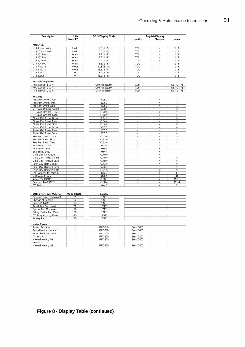
Operating & Maintenance Instructions 51
Description Units OBIS Display Code English Display
Note 1** Identifier Chevron Index
TOU (1-8)
1 - 8 Import kWh kWh 1.8.(1 - 8) TOU - 1 - 8
1 - 8 Export kWh kWh 2.8.(1 - 8) TOU - 1 - 8
1 - 8 Q1 kvarh kvarh 5.8.(1 - 8) TOU - 1 - 8
1 - 8 Q2 kvarh kvarh 6.8.(1 - 8) TOU - 1 - 8
1 - 8 Q3 kvarh kvarh 7.8.(1 - 8) TOU - 1 - 8
1 - 8 Q4 kvarh kvarh 8.8.(1 - 8) TOU - 1 - 8
1 - 8 kVAh 1 kVAh D.8.(1 - 8) TOU - 1 - 8
1 - 8 kVAh 2 kVAh E.8.(1 - 8) TOU - 1 - 8
1 - 8 CD 1 ** A.8.(1 - 8) TOU - 1 - 8
1 - 8 CD 2 ** B.8.(1 - 8) TOU - 1 - 8
External Registers
Register Set 1 (1-4) - User selectable Cum - S1 - (1 - 4)
Register Set 2 (1-4) - User selectable Cum - S2 - (1 - 4)
Register Set 3 (1-4) - User selectable Cum - S3 - (1 - 4)
Security
Program Event Count - C.2.0 - 4 1
Program Event Time - C.2.0 - 4 1
Program Event Date - C.2.0 - 4 1
CT Ratio Change Count - C.72.0 - 4 2
CT Ratio Change Time - C.72.0 - 4 2
CT Ratio Change Date - C.72.0 - 4 2
Phase Fail Event Count - C.54.0 - 4 3
Phase Fail Event Time - C.54.0 - 4 3
Phase Fail Event Date - C.54.0 - 4 3
Power Fail Event Count - C.7.0 - 4 4
Power Fail Event Time - C.7.0 - 4 4
Power Fail Event Date - C.7.0 - 4 4
Rev Run Event Count - C.53.0 - 4 5
Rev Run Event Time - C.53.0 - 4 5
Rev Run Event Date - C.53.0 - 4 5
End Billing Count - 0.1.0 - 4 7
End Billing Time - 0.9.6 - 4 7
End Billing Date - 0.9.7 - 4 7
Main Cov RemCount - C.70.0 - 4 8
Main Cov Remove Time - C.70.0 - 4 8
Main Cov Remove Date - C.70.0 - 4 8
Term Cov Rem Count - C.71.0 - 4 9
Term Cov Remove Time - C.71.0 - 4 9
Term Cov Remove Date - C.71.0 - 4 9
Est Battery Life Remain - C.6.0 - 4 10
In Service Hours - C.8.0 - 4 11
Active Tariff CRC - C.80.1 - 4 CrC1
Deferred Tariff CRC - C.80.4 - 4 CrC4
CT Ratio - 0.4.2 4 Ct
EOB Events (All Meters) Code (HEX) Display
Program Date or Midnight 01 rESEt
Change of Season 02 rESEt
Deferred Tariff 04 rESEt
Serial Port Command 08 rESEt
Optical Port Command 10 rESEt
Billing Pushbutton Press 20 rESEt
CT Programming Event 40 rESEt
Battery Fail 80 rESEt
Meter Errors -
Power fail data - FF 0040 Error 0040
Period backup data error - FF 0080 Error 0080
ROM checksum error - FF 0100 Error 0100
I2C Bus error - FF 0200 Error 0200
Internal battery life exceeded
- FF 0400 Error 0400
Internal battery fail - FF 0800 Error 0800
Figure 8 - Display Table (continued)

52 A1120/40 - Electronic Polyphase Meter
Elster Metering Limited - M181 001 2H - 11/2011
Description Units OBIS Display Code English Display
Note 1** Identifier Chevron Index
Historical (Most recent only)
Total Import kWh kWh 1.8.0.1 CUM - H1
Total Export kWh kWh 2.8.0.1 CUM - H1
Q1 kvarh kvarh 5.8.0.1 CUM - H1
Q2 kvarh kvarh 6.8.0.1 CUM - H1
Q3 kvarh kvarh 7.8.0.1 CUM - H1
Q4 kvarh kvarh 8.8.0.1 CUM - H1
Import kVAh kVAh D.8.0.1 CUM - H1
Export kVAh kVAh E.8.0.1 CUM - H1
Total Import kWh Phase A * kW 21.8.0.1 CUM 1 H1 A
kWh Phase B * kW 41.8.0.1 CUM 1 H1 B
kWh Phase C * kW 61.8.0.1 CUM 1 H1 C
Total Export kWh Phase A * kW 21.8.0.1 CUM 2 H1 A
kWh Phase B * kW 41.8.0.1 CUM 2 H1 B
kWh Phase C * kW 61.8.0.1 CUM 2 H1 C
Customer Defined 1 ** A.8.0.1 CUM - H1
Customer Defined 2 ** B.8.0.1 CUM - H1
Historical MD’s
1 - 4 Import kW kW 1.6.(1 - 4).1 MAX DEM - H1 (1 - 4)
1 - 4 Import Time - 1.6.(1 - 4).1 MAX DEM - H1 (1 - 4)
1 - 4 Import Date - 1.6.(1 - 4).1 MAX DEM - H1 (1 - 4)
1 - 4 Export kW kW 2.6.(1 - 4).1 MAX DEM - H1 (1 - 4)
1 - 4 Export Time - 2.6.(1 - 4).1 MAX DEM - H1 (1 - 4)
1 - 4 Export Date - 2.6.(1 - 4).1 MAX DEM - H1 (1 - 4)
1 - 4 Q1 kvar kvar 5.6.(1 - 4).1 MAX DEM - H1 (1 - 4)
1 - 4 Q1 Time - 5.6.(1 - 4).1 MAX DEM - H1 (1 - 4)
1 - 4 Q1 Date - 5.6.(1 - 4).1 MAX DEM - H1 (1 - 4)
1 - 4 Q2 kvar kvar 6.6.(1 - 4).1 MAX DEM - H1 (1 - 4)
1 - 4 Q2 Time - 6.6.(1 - 4).1 MAX DEM - H1 (1 - 4)
1 - 4 Q2 Date - 6.6.(1 - 4).1 MAX DEM - H1 (1 - 4)
1 - 4 Q3 kvar kvar 7.6.(1 - 4).1 MAX DEM - H1 (1 - 4)
1 - 4 Q 3 Time - 7.6.(1 - 4).1 MAX DEM - H1 (1 - 4)
1 - 4 Q3 Date - 7.6.(1 - 4).1 MAX DEM - H1 (1 - 4)
1 - 4 Q4 kvar kvar 8.6.(1 - 4).1 MAX DEM - H1 (1 - 4)
1 - 4 Q4 Time - 8.6.(1 - 4).1 MAX DEM - H1 (1 - 4)
1 - 4 Q4 Date - 8.6.(1 - 4).1 MAX DEM - H1 (1 - 4)
1 - 4 kVA 1 kVA D.6.(1 - 4).1 MAX DEM - H1 (1 - 4)
1 - 4 kVA 1 Time - D.6.(1 - 4).1 MAX DEM - H1 (1 - 4)
1 - 4 kVA 1 Date - D.6.(1 - 4).1 MAX DEM - H1 (1 - 4)
1 - 4 kVA 2 kVA E.6.(1 - 4).1 MAX DEM - H1 (1 - 4)
1 - 4 kVA 2 Time - E.6.(1 - 4).1 MAX DEM - H1 (1 - 4)
1 - 4 kVA 2 Date - E.6.(1 - 4).1 MAX DEM - H1 (1 - 4)
1 - 4 CD 1 ** A.6.(1 - 4).1 MAX DEM - H1 (1 - 4)
1 - 4 CD 1 Time ** A.6.(1 - 4).1 MAX DEM - H1 (1 - 4)
1 - 4 CD 1 Date ** A.6.(1 - 4).1 MAX DEM - H1 (1 - 4)
1 - 4 CD 2 ** B.6.(1 - 4).1 MAX DEM - H1 (1 - 4)
1 - 4 CD 2 Time ** B.6.(1 - 4).1 MAX DEM - H1 (1 - 4)
1 - 4 CD 2 Date ** B.6.(1 - 4).1 MAX DEM - H1 (1 - 4)
Historical Registers
CUM MD 1- 4 Import kW kW 1.2.(1 - 4).1 CUM MAX DEM - H1 (1 - 4)
CUM MD 1 - 4 Export kW kW 2.2.(1 - 4).1 CUM MAX DEM - H1 (1 - 4)
CUM MD Q1 1 - 4 kvar kvar 5.2.(1 - 4).1 CUM MAX DEM - H1 (1 - 4)
CUM MD Q2 1 - 4 kvar kvar 6.2.(1 - 4).1 CUM MAX DEM - H1 (1 - 4)
CUM MD Q3 1 - 4 kvar kvar 7.2.(1 - 4).1 CUM MAX DEM - H1 (1 - 4)
CUM MD Q4 1 - 4 kvar kvar 8.2.(1 - 4).1 CUM MAX DEM - H1 (1 - 4)
CUM MD kVA 1 1 - 4 kVA kVA D.2.(1 - 4).1 CUM MAX DEM - H1 (1 - 4)
CUM MD kVA 2 1 - 4 kVA kVA E.2.(1 - 4) 1 CUM MAX DEM - H1 (1 - 4)
CUM MD CD 1 1 - 4 ** A.2.(1 - 4).1 CUM MAX DEM - H1 (1 - 4)
CUM MD CD 2 1 - 4 ** B.2.(1 - 4).1 CUM MAX DEM - H1 (1 -4)
TOU 1 - 8 Import kWh kWh 1.8.(1 - 8).1 TOU - H1 (1 -8)
TOU 1 - 8 Export kWh kWh 2.8.(1 - 8).1 TOU - H1 (1 - 8)
TOU 1 - 8 Q1 kvarh kvarh 5.8.(1 - 8).1 TOU - H1 (1 - 8)
TOU 1 - 8 Q2 kvarh kvarh 6.8.(1 - 8).1 TOU - H1 (1 - 8)
TOU 1 - 8 Q3 kvarh kvarh 7.8.(1 - 8).1 TOU - H1 (1 - 8)
TOU 1 - 8 Q4 kvarh kvarh 8.8.(1 - 8).1 TOU - H1 (1 - 8)
TOU 1 - 8 kVAh 1 kVAh D.8.(1 - 8).1 TOU - H1 (1 - 8)
TOU 1 - 8 kVAh 2 kVAh E.8.(1 - 8).1 TOU - H1 (1 - 8)
TOU 1 - 8 CD 1 ** A.8.(1 - 8).1 TOU - H1 (1 - 8)
TOU 1 - 8 CD 2 ** B.8.(1 - 8).1 TOU - H1 (1 - 8)
Rev Run Count - C.53.0.1 - 4 H1 5
Phase Fail Count - C.54.0.1 - 4 H1 3
Power Fail Count - C.7.0.1 - 4 H1 4
Program Count - C.2.0.1 - 4 H1 1
CT Ratio Change Count - C.72.0.1 - 4 H1 2
Main Cover Remove Count - C.70.0.1 - 4 H1 8
Term Cover Remove Count - C.71.0.1 - 4 H1 9
End Billing Count - 0.1.0.1 - 4 H1 7
In Service Hours - C.8.0.1 - 4 H1 11
Estimated Battery Life - C.6.0.1 - 4 H1 10
Figure 8 - Display Table (continued)

Operating & Maintenance Instructions 53
Description Units OBIS Display Code English Display
Note 1** Identifier Chevron Index
Instrumentation
Volts Phase A V 32.7.0 - - Ins A
Volts Phase B V 52.7.0 - - Ins B
Volts Phase C V 72.7.0 - - Ins C
Current Phase A A 31.7.0 - - Ins A
Current Phase B A 51.7.0 - - Ins B
Current Phase C A 71.7.0 - - Ins C
Watts Phase A kW 21.7.0 - - Ins A
Watts Phase B kW 41.7.0 - - Ins B
Watts Phase C kW 61.7.0 - - Ins C
Watts Phase System Import kW 1.7.0 - - Ins
Watts Phase System Export kW 2.7.0 - - Ins
Phase Angle Phase A - 81.7.4 - - Ins A
Phase Angle Phase B - 81.7.15 - - Ins B
Phase Angle Phase C - 81.7.26 - - Ins C
Phase Rotation - C.90.0 - - Ins
Power Factor Phase A - 33.7.0 - - Ins A
Power Factor Phase B - 53.7.0 - - Ins B
Power Factor Phase C - 73.7.0 - - Ins C
PF Phase System - 14.7.0 - - Ins
Frequency Phase A - 34.7.0 - - Ins A
Frequency Phase B - 54.7.0 - - Ins B
Frequency Phase C - 74.7.0 - - Ins C
Note 1 - ** Units depend on register selected
* Available for Model Code Feature Set F only
Figure 8 - Display Table (Instrumentation)
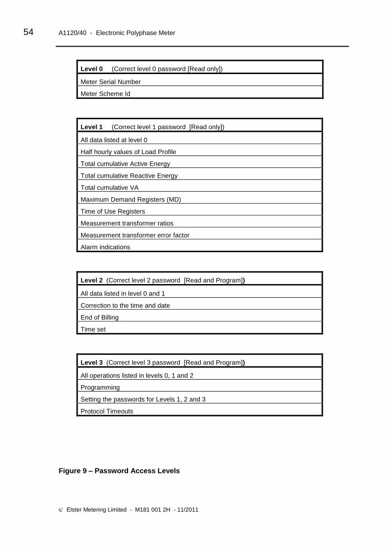
54 A1120/40 - Electronic Polyphase Meter
Elster Metering Limited - M181 001 2H - 11/2011
Level 0 (Correct level 0 password [Read only])
Meter Serial Number
Meter Scheme Id
Level 1 (Correct level 1 password [Read only])
All data listed at level 0
Half hourly values of Load Profile
Total cumulative Active Energy
Total cumulative Reactive Energy
Total cumulative VA
Maximum Demand Registers (MD)
Time of Use Registers
Measurement transformer ratios
Measurement transformer error factor
Alarm indications
Level 2 (Correct level 2 password [Read and Program])
All data listed in level 0 and 1
Correction to the time and date
End of Billing
Time set
Level 3 (Correct level 3 password [Read and Program])
All operations listed in levels 0, 1 and 2
Programming
Setting the passwords for Levels 1, 2 and 3
Protocol Timeouts
Figure 9 – Password Access Levels

Operating & Maintenance Instructions 55
APPENDIX A - Checking kWh and kvarh Registration Accuracy
WARNING
Only trained and competent personnel, familiar with meter test procedures should carry out the
following operation.
A1 Introduction
Various methods of checking the accuracy of registration of the A1120/40 meter are available. Methods using the LED test indicators and Register advances are described below.
A2 Checking Meter Accuracy Using the LED Test Indicator
The LED test indicators are configured at manufacture to pulse for import kWh and import kvarh (import only meter) or pulse for import plus export kWh and kvarh (import/export or power flow insensitive meters).
A2.1 Comparing the number of LED pulses with substandard meter register advance
What you will need
Suitable test equipment with a sensor to detect LED pulses
A suitable substandard meter (set to the same system configuration as the meter under test)
A counter for counting the number of LED pulses
Checking registration
In order to achieve a repeatability of 0.1% the test time at any load needs to be a minimum of 60 seconds.
1. Connect the test equipment and a suitable load to the meter, then power up the meter
2. The right hand Test LED pulses for kWh
3. Run the test for a suitable duration and check the amount the substandard has advanced and the number of pulses detected
Calculate the registration by dividing the number of pulses by the meter constant.
e.g. 994 (LED count) = 0.994 kWh advance. 1000 (meter constant)
Compare this kWh advance with the amount the substandard has advanced.
Repeat for kvarh using left hand Test LED.
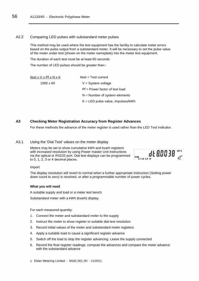
56 A1120/40 - Electronic Polyphase Meter
Elster Metering Limited - M181 001 2H - 11/2011
A2.2 Comparing LED pulses with substandard meter pulses
This method may be used where the test equipment has the facility to calculate meter errors
based on the pulse output from a substandard meter. It will be necessary to set the pulse value
of the meter under test (shown on the meter nameplate) into the meter test equipment.
The duration of each test must be at least 60 seconds
The number of LED pulses should be greater than:-
Itest x V x Pf x N x K Itest = Test current
1000 x 60 V = System voltage
Pf = Power factor of test load
N = Number of system elements
K = LED pulse value, impulses/kWh
A3 Checking Meter Registration Accuracy from Register Advances
For these methods the advance of the meter register is used rather than the LED Test Indicator.
A3.1 Using the 'Dial Test' values on the meter display
Meters may be set to show cumulative kWh and kvarh registers with increased resolution by using Power master Unit instructions via the optical or RS232 port. Dial test displays can be programmed to 0, 1, 2, 3 or 4 decimal places. Import
The display resolution will revert to normal when a further appropriate instruction (Setting power down count to zero) is received, or after a programmable number of power cycles.
What you will need
A suitable supply and load or a meter test bench.
Substandard meter with a kWh (kvarh) display.
For each measured quantity:
1. Connect the meter and substandard meter to the supply
2. Instruct the meter to show register to suitable dial test resolution
3. Record initial values of the meter and substandard meter registers
4. Apply a suitable load to cause a significant register advance
5. Switch off the load to stop the register advancing. Leave the supply connected
6. Record the final register readings, compute the advances and compare the meter advance with the substandard advance

Operating & Maintenance Instructions 57
APPENDIX B - RS232 Multi-drop Mode
A1120/40 meters allow up to 12 meters to be connected in RS232 multi-drop configuration. Two-way RJ11 adaptors will be required to link each meter in the chain.
B1 RS232 Multi-drop Installation Procedure
The connection diagram for RS232 multi-drop mode is shown below
1. Observe all Safety Warnings, Warnings, Precautions for handling electrostatic discharge sensitive devices and EMC Guidelines in Section 2
2. Remove the terminal cover from the meters. If the terminal cover plate is not in place, switch off all supplies to the meter.
3. Connect a two-way RJ11 adaptor to the RJ11 port of the first meter in the multi-drop chain
4. Connect an RS232 cable from the PC to the first port of the RJ11 as shown below
5. Connect a Flat Pin Cable to the second port of the RJ11 adaptor
6. Replace the terminal cover and fit appropriate seals
7. Connect a two-way RJ11 adaptor to the RJ11 port of the second meter in the multi-drop chain
8. Connect the flat pin cable from the first meter to the RJ11 adaptor of the second meter in the multi-drop chain
9. Connect a Flat Pin Cable to the second port of the RJ11 adaptor
10. Replace the terminal cover and fit appropriate seals
11. Continue as steps 7 to 10 to the next meter
12. When all multi-drop connections are made and all terminal covers are in place, switch on the supplies
R 11 AdaptorJ R 11 AdaptorJ
Next Meter
From PC Flat Pin Cable
Rx (2)
Tx (3)No Connection (4)
Zero Volts (5)
(2) Tx
(3) Rx(4)(5)
RJ11 Connector
6 5 4 3 2 1

58 A1120/40 - Electronic Polyphase Meter
Elster Metering Limited - M181 001 2H - 11/2011
APPENDIX C - RS485 Multi-drop Mode
A1120/40 meters allow up to 12 meters to be connected in RS485 multi-drop configuration. Two-way RJ11 adaptors will be required to link each meter in the chain.
Amplicon Amplicon Amplicon
8 7 6 5 4 3 2 1 8 7 6 5 4 3 2 1 8 7 6 5 4 3 2 1
25-way D type 25-way D type 25-way D type
+VDC 7 4 2 3 +VDC 7 4 2 3
6 5 4 3 2 1 6 5 4 3 2 1
RJ11RJ11
W
hite
W
hite
Bla
ck
Bla
ck
Ye
llo
w
Ye
llo
w
Blu
e
B
lue
Next Meter
1: 2: 3: B4: A5: A16: B1
7: VCD8: Gnd
Gnd
+V
PCStandard 9-25 Way Lead

Operating & Maintenance Instructions 59
APPENDIX D - External Battery Module
D1 External Battery Module
An External Battery Module can be fitted as an option which allows reading of meter data via the optical port and access to the display facilities during power outages. The battery is housed in the Module Carrier that fits below the meter terminal cover.
The Battery Module connects to the meter via a special „Molex‟ connector.
The 'Molex' connector is optional. The use of the External Battery Module must be specified at the time the meters are ordered.
External Battery Status
The battery voltage is monitored to detect if it has failed. A new battery install date can be programmed and can be read back from the meter.
Using the External Battery Facility during Power Outages
The External Battery facility will only operate when power has been removed from the meter. The module is energised by pressing the display pushbutton.
Once the module has been energised-
Displays can cycled in the normal way using the pushbuttons
Meter data can be read via the optical port (note that the communications session will always be completed before power is removed)
External Battery Module power will be removed from the meter if the 'No button time-out' (programmable from 10 to 120 seconds using the Power Master Unit) has expired.

60 A1120/40 - Electronic Polyphase Meter
Elster Metering Limited - M181 001 2H - 11/2011
D2 Installation
WARNINGS
Read Section 2 (Warnings) before installing the Battery Module.
Check that the terminal cover plate is in place before installing the module. If the terminal cover plate is not in place, all supplies to the meter must be isolated.
For correctly installed 3 phase 4 wire meters, one of the battery connections will be at 'Mains Neutral' potential. Under fault conditions, this connection could be raised to a 'Fatally Dangerous Potential'.
For 3 phase 3 wire meters, one of the battery connections will be at 'Mains Phase Potential'.
The External Battery Module and its connection leads are double insulated. No attempt should be made to modify the assembly or open the module housing. A replacement assembly must be used if the battery becomes exhausted.
Failure to follow these instructions may result in electric shock or death.
Installing the Module
1. Read the Warnings above
2. Remove the meter terminal cover
3. If the terminal cover plate is not in place, do not attempt to install the module unless all supplies to the meter have been isolated
4. Clip the Battery Module over the Terminal Block as shown in Section D1
5. Connect the 'Polarised Molex connector' to the 'Molex socket' making sure the cable is routed in the recess by the 'Terminal Block Screw Holder' as shown in Section D1
6. Replace the terminal cover
Technical Information
Battery Type (Alkaline zinc manganese dioxide) +9 Volt PP3 (IEC 6LR61)
Battery Life 5 years with one reading session each month
Battery Safety See Warnings, Section 2
Specifications 550 mA hours

Operating & Maintenance Instructions 61
Certificate of Conformity


![Untitled-4 [] · Standard lamineret (8 meter / *4 meter) Neon lamineret - 5 meter Mat lamineret - 8 meter / **5 meter) Metallic lamineret - 8 meter Ulamineret - 8 meter Fleksibel](https://img.dokumen.tips/doc/110x75/5f3a768af7b8e86a6437cff7/untitled-4-standard-lamineret-8-meter-4-meter-neon-lamineret-5-meter.jpg)