Embed Size (px)
Citation preview

Source: Proceedings of the 20th International Modal Analysis Conference (IMAC XX), Los Angeles, CA, USA, February 4-7, 2002.
A WIRELESS MODULAR MONITORING SYSTEM FOR CIVIL STRUCTURES
Jerome Peter Lynch, Kincho H. Law, Anne S. Kiremidjian, Thomas Kenny and Ed Carryer
The John A. Blume Earthquake Engineering Center Department of Civil and Environmental Engineering
Stanford University, Stanford, CA 94305
ABSTRACT A novel wireless sensing unit for real-time structural response measurements has been designed and fabricated. Using available technologies from the marketplace, a low cost alternative to traditional wire-based sensing systems has been developed. In particular, wireless communication capabilities are included through the integration of reliable wireless modems with each unit. A wireless infrastructure lowers overall system installation costs by eliminating laborious cabling tasks. For sensor control and data interrogation, a RISC microprocessor computational core is used. As a result, the computational burden of the centralized data logger is placed on the individual sensing units. A wide array of different sensors can be interfaced to the unit delivering a sensor transparent module. As a means of system validation, a small-scale two-story model structure is instrumented and excited with modal analysis performed on the time history response. 1. INTRODUCTION There is a clear need for a rational and economical method of monitoring the performance and safety of civil structures throughout their life spans. To offset the high installation and upkeep costs associated with a permanent monitoring system, only structures that fulfill an essential role in society or those with high everyday demand, are instrumented. Owners of ordinary structures are reluctant to pay for monitoring systems especially when they consider them an unnecessary yet expensive amenity. It is easy to expound the many benefits associated with monitoring the performance of structures. For example, recordings of structures during ambient vibrations and seismic disturbances are essential in determining the demand placed upon structures. In the case of structures in high seismic areas, information provided by monitoring structural responses will inevitably lead to better scientific understanding of how structures behave in the nonlinear
realm. Many notable cases can be cited that prove the value associated with monitoring key structures. For instance, measurements taken of the County Services building during the 1979 Imperial Valley earthquake revealed striking discontinuities of the building’s time history response indicating sudden changes in structural integrity during the disturbance [1]. Within the structural health monitoring research community, a significant amount of research is focused upon developing ways of detecting damage in structures [2]. An integral component of a health monitoring system is a network of sensors that will provide the damage detection algorithms with time history response measurements of the structure. Damage detection strategies that can hypothesize potential locations of damage will need dense arrays of sensors located throughout a structure. The future implementation of damage detection systems employing low cost monitoring can assist in the long-term assessment of structural retrofit needs. Commercial structural monitoring systems can find their origins in data acquisition systems used regularly in the laboratory. Current monitoring systems employ hub-spoke system architectures with centralized data units used for retrieving data from remote wired sensors. Systems of this type are optimized in their design to be well suited for small structures tested in the laboratory. Unfortunately, they do not scale well when used for large-scale system implementation such as in bridges and buildings. As a result, installation time and costs can be very high. For example, installation time of a moderate size monitoring system can consume over 75% of the total system testing time with installation costs approaching over 25% of the total system cost. In the state of California, 61 of the state’s 22,000 bridges have been instrumented with costs reported to be well over $300,000 per toll bridge for a 60-channel system. A large portion of this cost includes the laying of conduits needed to protect wires from harsh weather conditions at a cost of $10 per linear foot [3].

2. WIRELESS MODULAR MONITORING SYSTEMS
A low cost alternative to the widely used traditional wire-based monitoring system is proposed for application in civil structures, as shown in Figure 1. The realization of such a low cost monitoring system is now possible due to the reducing price and rapid advancement of key technologies such as sensors, microprocessors, wireless networks and integrated circuits. The single most important innovation of the proposed system is the inclusion of wireless communication into the sensing units. Wireless communication eradicates the need for wires and therefore represents a significant cost reduction over a wire-based counterpart. In addition to its cost benefits, the wireless infrastructure provides the system tremendous flexibility. Different network configurations can now be utilized such as the centralized hub-spoke architecture, peer-to-peer (P2P) architecture, and hybrid architectures combining the two. The flexibility of the wireless communication network of system sensors allows for system modularity as well as reduced dependence upon a centralized data acquisition unit for coordination of system activities. The new wireless systems are termed Wireless Modular Monitoring Systems, or rather, WiMMS [4].
Sensor
Sensor
Sensor
Sensor
SensorCentralized Data
Acquisition
WiMMSSensor
WiMMSSensor
WiMMSSensor
WiMMSSensor
WiMMSSensor
Centralized Data Storagewith Wireless Modem
Figure 1 – Evolution from a Cable-Based Monitoring
System to a Wireless Monitoring System
Another significant innovation of the system is the migration of computational power from the centralized data acquisition system to the sensor units. The distributed on-board computational power of the system
can potentially facilitate parallel data processing that will render applications like damage detection procedures feasible in real time. 3. DESIGN OF THE WIRELESS SENSING UNIT A fully functional proof-of-concept sensing unit to be used in the proposed WiMMS system has been designed and fabricated from commercially available components. An overview diagram of the sensing unit is shown in Figure 2. Described below is the motivation and criteria used in the selection of some of the system components as well as a detailed description of how they work.
16-bit Parallel TexasInstrument A/D
Converter
Radio Modem
Sync.Serial Port
Computational Core(Microcontroller)
In-SystemProgrammer
Flash/EEPROMMemory
16 Bit Bus
ADAccelerometer
ADXL210
Digital I/O
Future Implementation:
Data LoggingSRAM
Future Implementation:Real Time Clock
Figure 2 – Functional Layout of the Proof-of-Concept
Wireless Sensing System Computational Core Perhaps the most important choice in the development of the wireless sensing unit is the hardware chosen to act as the unit’s computational core. This core will be responsible not only for aggregation of sensing data from on-board sensing transducers (i.e. accelerometers), but they will also take part in the task of cleansing and processing the data. Various suitable alternatives are available ranging from field programmable gate arrays (FPGA) to digital signal processing (DSP) chips. The final selection was based upon the criteria of efficient power consumption characteristics of the core. As a result, a microcontroller core architecture was chosen because of their low power and high performance specifications. In particular, an enhanced Atmel RISC microcontroller was selected from microcontrollers currently available on the market. The Atmel AVR microcontroller is an 8-bit microcontroller with a full suite of on-board services such as internal oscillators, serial communication UARTS, timers,

pulse width modulators (PWM), and four 8-bit input/output ports. The Atmel RISC microcontroller provides a high performance solution with inherently low power consumption characteristics. The enhanced RISC (Reduced Instruction Set Computer) architecture of the microcontroller provides computational speed by reducing the ordinary instruction set available to CISC (Complex Instruction Set Computer) microcontrollers, thereby allowing single cycle instruction execution [5]. This means code is executed at the same rate as the microcontroller’s 4 MHz clock. The Atmel RISC microcontroller is enhanced with additional instructions to allow for CISC like execution without compromising RISC performance. The design of the microcontroller’s architecture is optimized for using high-level languages such as C and Java for programming the microcontroller [6]. On an ordinary 8-bit microcontroller, the use of a high level language for programming adds significant overhead to the microcontroller’s code execution since they are optimized with the assumption that they would be programmed using assembly. By providing 32 8-bit general purpose registers and 3 16-bit pointers, the Atmel AVR microcontroller allows for high code density when using high-level languages for programming. The large number of general purpose registers is necessary for allowing local variable definitions while the 3 16-bit pointers are useful for allowing indirect jumps and elegant data memory accessing. Wireless Communications Resonating with the demands of the current monitoring system end users, a low cost but highly reliable wireless solution that allows for peer to peer (P2P) communication as well as communication with a central data logging unit, is sought. This task can be accomplished using wireless modem technology. The Proxim ProxLink MSU2 wireless modem was selected for inclusion with the proposed wireless sensing unit. Operating in the unlicensed 902-928 MHz Industrial, Scientific, Medical (ISM) radio band, the radio modem employs direct sequence spread spectrum communication techniques to ensure a secure digital communication link between modems. Data to be transmitted using direct sequence spread spectrum is multiplied by a pseudo-noise spreading sequence (also known as a chirping code). The resulting pseudo-noise signals appear random but can be reproduced deterministically at the receiver. Multiple users can simultaneously access the same wireless bandwidth without interference since each user employs a unique pseudo-noise sequence that is orthogonal to all other sequences [7]. The ProxLink wireless modems encode each bit of data with an 11-bit pseudo-noise chirping code. The guarantee of a reliable digital communication channel between wireless modems is attained using the spread spectrum techniques described. Concentrating data upon a narrow frequency band is avoided by spreading the transmittable signal over multiple frequency channels
within the available radio band. Spread spectrum communication is less sensitive to narrow band interference that can be generated by ordinary industrial machines and other radio devices located within close proximity to the wireless network. Specifically, the ProxLink modems divide the available 902-928 MHz band into three distinct channels each with 160 frequency bands. The modems transmit on one channel alternating between the 160 individual bands. The range of the ProxLink modems in open space is as far as 1000 feet. The communication range of the ProxLink modems inside buildings has been shown to be as far as 100 feet [4]. Within buildings, the shielding behavior of common structural materials such as steel and concrete cause a reduction of power of the radio frequencies [8]. Empirical studies reveal that the higher the radio frequency, the better the building penetration characteristics of the signal within heavily constructed buildings. For lighter construction such as wood framed houses, lower frequencies perform better since they have better diffraction properties within the structure [9]. Sensing Transducers There exist a large number of sensing transducers that can be used in the monitoring of structures. Some examples include strain gages, accelerometers, velocity meters, and displacement transducers. To ensure flexibility of the sensing unit, the overall design is sensor independent and is compatible with all analog sensors. A low noise, single channel, Texas Instrument 16-bit analog-to-digital (A/D) converter is used to measure the output voltage of the analog sensor and relay this measurement in digital form to the unit’s microcontroller. Given the wide spread use of accelerometers within the structural sensing field, accelerometers were considered in this study. In recent years, micro-electro mechanical system (MEMS) based accelerometers have become popular. By fabricating micrometer sized mechanical elements upon silicon, revolutionary sensors can be fabricated along with CMOS based circuits all on one die. The result is accurate and sensitive sensors in form factors and unit costs not previously possible. In particular, the two MEMS accelerometers considered were the Analog Device’s ADXL210 10g digital accelerometer as well as a high performance piezoresistive planar accelerometer fabricated by Professor Thomas Kenny’s group at Stanford University. Analog Devices ADXL210 Analog Device’s ADXL210 accelerometer is a low cost, low power accelerometer that can measure acceleration on two axes. The internal architecture of the accelerometer uses balanced differential capacitors to measure acceleration. The MEMS accelerometer is fabricated as a surface micromachined polysilicon structure placed upon a silicon wafer that houses signal conditioning circuitry for open loop acceleration measurement. A duty cycle modulator within the signal conditioning circuitry provides an anti-aliased digital signal for direct input to a microcontroller. The resolution of the
duty cycle modulator is 14 bits, which is better than the accelerometer itself. The performance characteristics of the accelerometer can be calibrated by judiciously selecting filtering resistors and capacitors at the analog signal pins of the accelerometer. A tradeoff exists between the bandwidth and resolution of the accelerometer with greater bandwidths causing reduced resolution. For application in structural monitoring systems, the bandwidth of both axes of the ADXL210 is set to 50 Hz providing an RMS resolution of 4 mg. High Performance Piezoresistive Accelerometer In the high performance planar accelerometer, designed by Professor Kenny’s group at Stanford University, a large proof mass is connected to a rigid base with a cantilevering element. The element is very slender allowing for easy deflection only in the horizontal plane of the accelerometer (see Figure 3). Some out-of-plane response could be experienced but would have little to no effect on the resulting acceleration reading. Piezoresistors, a material that produces voltage in direct proportion to tensile and compressive strain, are implanted along the flexural sides of the cantilevering element. The strain experienced by these surfaces when the proof mass deflects is proportional to the sensor’s acceleration. As a result, voltage output of the accelerometer is directly proportional to the acceleration of the accelerometer’s packaging [10].
Lightly Implanted Piezoresistor
Proof Mass
Chip Surface
Heavily Implanted Conductors
Figure 3 – MEMS-Based High Performance Planar Piezoresistive Accelerometer
One nice attribute of the sensor is that its performance can be tuned for a specific application by simply changing the dimensions of the cantilevering element. For example, to maximize sensor sensitivity, the flexural width should be minimized while the mass radial length is maximized. A tradeoff exists between the bandwidth and the resolution of the accelerometer. With increased resolution, the resonant frequency of the sensor, and hence its bandwidth, is reduced. Over the full dynamic range of the sensor, the Kenny/Partridge accelerometers maintain nearly constant sensitivity implying a fairly linear transfer function of the accelerometer. The maximum value of the dynamic range of the accelerometer is a direct result of the proof mass being arrested by its wafer housing. This stopping mechanism allows the accelerometer to experience very high accelerations without breaking, as could be the case with the ADXL210. The end stops of the accelerometer also prevent the flexural element from entering the nonlinear region of response.
When compared against commercially available accelerometers, the experimental results of the accelerometers produced by the Kenny group are quite impressive. One set of accelerometers were designed and fabricated for specific adoption within the wireless structural sensing unit. This set of accelerometers has a radial length of 1 mm and a flexural width of 5 µm. The full dynamic range of the accelerometers are well above 10g with a resolution of 20 µg at an acceleration bandwidth of 650 Hz. Unit Packaging To accommodate all of the individual components of the system, a two-layer printed circuit board has been preliminarily designed. The printed circuit board is 4” by 4” in size and provides a convenient means of packaging all system components in an efficient manner. Low transient noise characteristics are ensured in the board design resulting in board performance as close as possible to the performance of the integrated circuits. The circuit board houses the microcontroller, the ADXL210, the 16-bit A/D as well as all the supporting circuitry. The A/D unit is used for reading acceleration measurements of the high performance planar accelerometer. The ProxLink wireless modem is externally attached to the circuit through a serial line originating from the modem’s serial port. With the accompanying 9V alkaline battery power supply, the current demonstration system can be contained within a sealed packaging unit roughly 5” by 4” by 1” in dimension as shown in Figure 4.
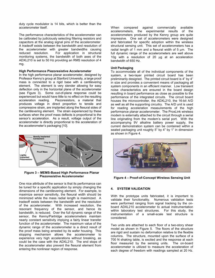
Figure 4 – Proof-of-Concept Wireless Sensing Unit 4. SYSTEM VALIDATION With the prototype units fabricated, it is important to validate their functionality. Numerous validation tests were performed ranging from signal tracking by the on-board ADXL210 accelerometer to actual instrumentation within laboratory test structures. For this study, the instrumentation of a small-scale test structure is considered. Two units are attached to each floor of a two-story shear model as shown in Figure 5. The floors of the structure are rigid and sustain no deformation relative to the flexible columns. The structure, mounted upon the surface of a 700 N shaking table, is excited and the response at each floor measured by the sensing units. The on-board accelerometer is utilized to measure the acceleration of each degree of freedom with readings sampled at 20 Hz.
The data is transmitted from both sensing units at each time step to a central data-logging computer.
Figure 5 – Two-Story Test Structure used in the System Validation Test
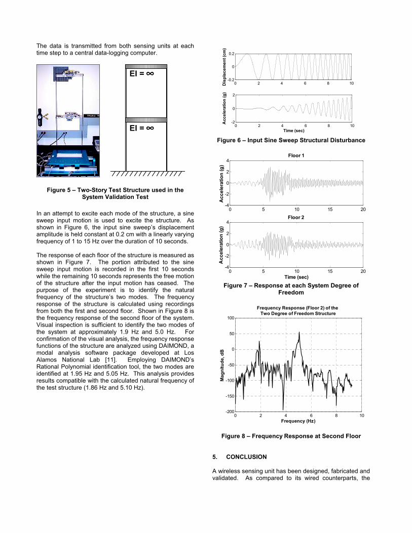
In an attempt to excite each mode of the structure, a sine sweep input motion is used to excite the structure. As shown in Figure 6, the input sine sweep’s displacement amplitude is held constant at 0.2 cm with a linearly varying frequency of 1 to 15 Hz over the duration of 10 seconds. The response of each floor of the structure is measured as shown in Figure 7. The portion attributed to the sine sweep input motion is recorded in the first 10 seconds while the remaining 10 seconds represents the free motion of the structure after the input motion has ceased. The purpose of the experiment is to identify the natural frequency of the structure’s two modes. The frequency response of the structure is calculated using recordings from both the first and second floor. Shown in Figure 8 is the frequency response of the second floor of the system. Visual inspection is sufficient to identify the two modes of the system at approximately 1.9 Hz and 5.0 Hz. For confirmation of the visual analysis, the frequency response functions of the structure are analyzed using DAIMOND, a modal analysis software package developed at Los Alamos National Lab [11]. Employing DAIMOND’s Rational Polynomial identification tool, the two modes are identified at 1.95 Hz and 5.05 Hz. This analysis provides results compatible with the calculated natural frequency of the test structure (1.86 Hz and 5.10 Hz).
0 2 4 6 8 10-0.2
0
0.2
Dis
plac
emen
t (cm
)
0 2 4 6 8 10-2
0
2
Acc
eler
atio
n (g
)
Time (sec)
Figure 6 – Input Sine Sweep Structural Disturbance
0 5 10 15 20-4
-2
0
2
4
Acc
eler
atio
n (g
)
Floor 1
0 5 10 15 20-4
-2
0
2
4Floor 2
Acc
eler
atio
n (g
)
Time (sec) Figure 7 – Response at each System Degree of
Freedom
0 2 4 6 8 10-200
-150
-100
-50
0
50
100
Mag
nitu
de, d
B
Frequency (Hz)
Frequency Response (Floor 2) of the Two Degree of Freedom Structure
Figure 8 – Frequency Response at Second Floor
5. CONCLUSION A wireless sensing unit has been designed, fabricated and validated. As compared to its wired counterparts, the
EI = ∞∞∞∞
EI = ∞∞∞∞

proposed wireless modular monitoring system delivers a compelling cost-benefit advantage as well as the guarantee of a quick yet flexible installation. With computational power included within the wireless units, it can be harnessed to perform computationally intensive procedures in real time. Through wireless collaboration, the units have the potential of solving complex problems characterized by high dimensionality in parallel. The proof-of-concept embeddable wireless monitoring system has been used in a series of validation tests. As presented here, it has proven to be reliable and accurate in identifying the modal properties of a laboratory test structure. Additional validation tests are planned to ensure a high level of performance when installed in the field. Additional WiMMS sensing units are currently being designed and fabricated for validation in a full scale structure. Future generation units will push the technology envelope by incorporating some new technologies just emerging on the marketplace. Efforts are already underway investigating advanced wireless devices that are more power efficient than the current ProxLink wireless modem. A Bluetooth wireless modem, supporting the ad-hoc Bluetooth wireless network protocol, is being considered as an alternative to be incorporated within the sensing unit.
ACKNOWLEDGEMENTS This research is partially sponsored by the National Science Foundation under Grant Number CMS-9988909. REFERENCES [1] Bolt, B. A., Seismic Instrumentation of Bridges and
Dams: History and Possibilities, Proceedings of the Instrumental Systems for Diagnostics of Seismic Response of Bridges and Dams, Consortium of Organizations for Strong-Motion Observation Systems, 2001.
[2] Doebling, S. W., Farrar, C. R., Prime, M. B., and
Shevitz, D. W., Damage Indentification and Health Monitoring of Structural and Mechanical Systems from Changes in Their Vibration Characteristics: A Literature Review, Report LA-13070-MS, Los Alamos National Laboratory, 1996.
[3] Hipley, P., Caltran’s Current State-of-Practice,
Proceedings of the Instrumental Systems for Diagnostics of Seismic Response of Bridges and Dams, Consortium of Organizations for Strong-Motion Observation Systems, 2001.
[4] Straser, E. G., A Modular Wireless Damage
Monitoring System for Structures, Ph.D. Thesis, Department of Civil and Environmental Engineering, Stanford University, Stanford, CA. pp. 18-20, 1998.
[5] AVR RISC Microcontroller Data Book, Atmel
Corporation, San Jose, CA, 1999. [6] Bogen, A. E. and Wollan, V., AVR Enhanced RISC
Microcontrollers, Technical Document, Atmel Corporation, Atmel Development Center, Trondheim, Norway, 1999.
[7] Rappaport, T. S., Wireless Communications:
Principles and Practice, Prentice Hall, Upper Saddle River, NJ, pp. 274–280, 1996.
[8] Anderson, J. B., Rappaport, T. S., and Yoshida,
S., Propagation Measurements and Models for Wireless Communication Channels, IEEE Communications Magazine, Vol. 33, No 1, pp. 42-49, 1994.
[9] Davidson, A. and Hill, C., Measurement of
Building Penetration Into Medium Buildings at 900 and 1500 MHz, IEEE Transactions on Vehicular Technology, Vol. 46, No. 1, pp. 161-168, 1997.
[10] Partridge, A., Reynolds, J. K., Chui, B. K., Chow,
E., Fitzgerald, A. M., Zhang L., Maluf, N., and Kenny, T. W., A High-Performance Planar Piezoresistive Accelerometer, IEEE Journal of Microelectricalmechanical Systems, Vol. 9, No. 1, pp. 58-65, 2000.
[11] Doebling, S. W., Farrar, C. R., and Cornwell, P.
J., DIAMOND: A Graphical Interface Toolbox for Comparative Modal Analysis and Damage Identification, Los Alamos National Lab, 1997 (http://www.lanl.gov/projects/damage_id/software.htm).