Embed Size (px)
Citation preview
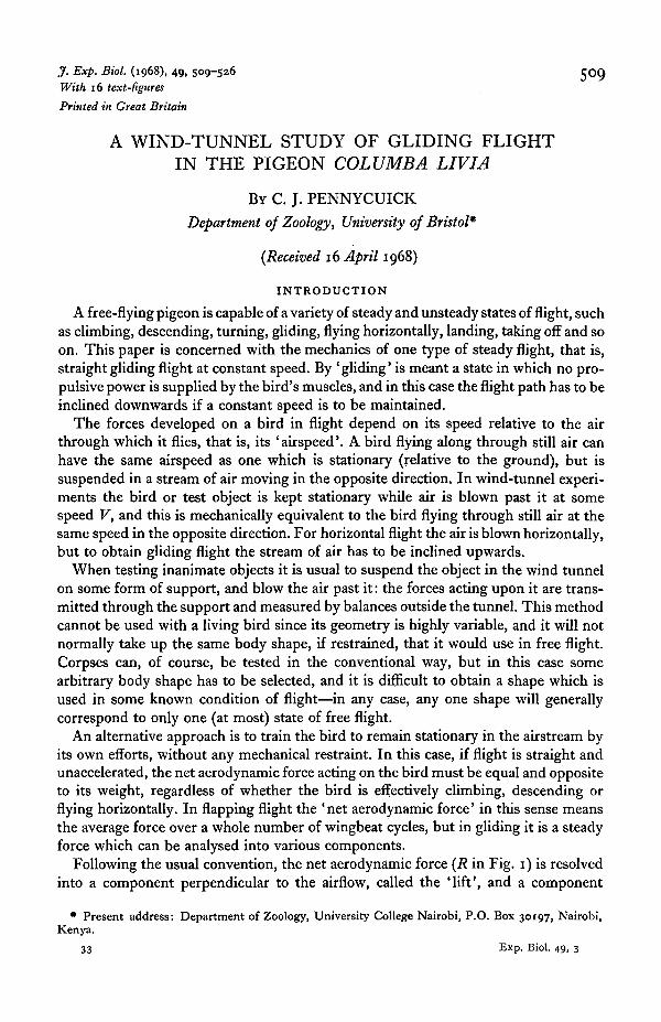
J. Exp. Biol. (1968), 49, 509-526 5 0 9With 16 text-figures
Printed in Great Britain
A WIND-TUNNEL STUDY OF GLIDING FLIGHTIN THE PIGEON COLUMBA LIVIA
BY C. J. PENNYCUICK
Department of Zoology, University of Bristol*
(Received 16 April 1968)
INTRODUCTION
A free-flying pigeon is capable of a variety of steady and unsteady states of flight, suchas climbing, descending, turning, gliding, flying horizontally, landing, taking off and soon. This paper is concerned with the mechanics of one type of steady flight, that is,straight gliding flight at constant speed. By 'gliding' is meant a state in which no pro-pulsive power is supplied by the bird's muscles, and in this case the flight path has to beinclined downwards if a constant speed is to be maintained.
The forces developed on a bird in flight depend on its speed relative to the airthrough which it flies, that is, its 'airspeed'. A bird flying along through still air canhave the same airspeed as one which is stationary (relative to the ground), but issuspended in a stream of air moving in the opposite direction. In wind-tunnel experi-ments the bird or test object is kept stationary while air is blown past it at somespeed V, and this is mechanically equivalent to the bird flying through still air at thesame speed in the opposite direction. For horizontal flight the air is blown horizontally,but to obtain gliding flight the stream of air has to be inclined upwards.
When testing inanimate objects it is usual to suspend the object in the wind tunnelon some form of support, and blow the air past it: the forces acting upon it are trans-mitted through the support and measured by balances outside the tunnel. This methodcannot be used with a living bird since its geometry is highly variable, and it will notnormally take up the same body shape, if restrained, that it would use in free flight.Corpses can, of course, be tested in the conventional way, but in this case somearbitrary body shape has to be selected, and it is difficult to obtain a shape which isused in some known condition of flight—in any case, any one shape will generallycorrespond to only one (at most) state of free flight.
An alternative approach is to train the bird to remain stationary in the airstream byits own efforts, without any mechanical restraint. In this case, if flight is straight andunaccelerated, the net aerodynamic force acting on the bird must be equal and oppositeto its weight, regardless of whether the bird is effectively climbing, descending orflying horizontally. In flapping flight the ' net aerodynamic force' in this sense meansthe average force over a whole number of wingbeat cycles, but in gliding it is a steadyforce which can be analysed into various components.
Following the usual convention, the net aerodynamic force (R in Fig. 1) is resolvedinto a component perpendicular to the airflow, called the 'lift', and a component
• Present address: Department of Zoology, University College Nairobi, P.O. Box 30197, Nairobi,Kenya.
33 Exp. Biol. 49, 3

510 C. J. PENNYCUICK
parallel to the airflow called the 'drag' (L and D respectively in Fig. i). If the airflowis inclined upwards at an angle a to the horizontal, then evidently
L = W.cos a,
D = W.sina,
where W is the bird's weight. Thus if W and a are measured, the lift and drag areeasily calculated.
The method used here appears to have been first proposed by Raspet (1950), whowould doubtless have developed it but for his untimely death in i960. Greenewalt
R
L
Fig. 1. In straight flight at a constant speed the bird's weight must be exactly balanced by thenet aerodynamic force R acting on it. In gliding flight the bird must descend at some angle abelow the horizontal—alternatively it can remain stationary in a stream of air inclined upwardsat this angle to the horizontal. R is resolved into two components—the drag D, in line with therelative airflow, and the lift L at right angles to it.
(1961) used a horizontal blower to determine the maximum level-flight speeds ofhummingbirds (Trochilidae), and recently Tucker (1968) has carried out respirometricand other measurements on budgerigars (Melopsittacus undulatus) flying in a windtunnel.
MATERIAL
The pigeons (Columbia livid) used were tame birds kept for the purpose, and wereallowed to fly free from time to time. Six birds were successfully trained to fly in thewind tunnel (see p. 513), but only one was sufficiently co-operative over a longperiod to yield good gliding measurements over the entire speed range. The dataplotted in the graphs all refer to this one individual, although measurements in partsof the speed range, which in no way conflicted with those presented, were obtainedfrom two other pigeons.

Gliding flight of the pigeon 511
METHODS
The wind tunnel was an open-jet, open-circuit blower, this layout being selectedbecause the whole tunnel had to be mounted on trunnions for tilting, and thereforeneeded to be short and compact. The main dimensions are shown in Fig. 2.
An octagonal jet 1 m. across was chosen, this being judged the smallest which wouldsatisfactorily accommodate a large pigeon with its wings fully spread (70 cm.). Thediameter of the upstream end was limited by the need to fit the tunnel into a stairwell 4-3 m. across (the only available site), leaving sufficient room for circulation of
Fig. 2. The wind tunnel is suspended from a support beam a and pivoted about a horizontalaxis passing through b. The fan c sucks air in through the intake filter d (composed of \ in. wiremesh). Swirl is removed by a ring of stator vanes e, and a 3 in. thickness of \ in. metal honey-comb/. The screen g is placed at the upstream end of the contraction h. The whole tunnel canbe tilted to an angle a above the horizontal. The pigeon flies just outside the end of the contrac-tion, which is octagonal in cross-section (bottom right): the pigeon retrieves food reward from atea-spoon i soldered to the end of a length of i in. brass tube passing diagonally across the work-ing section.
air and pedestrians round the outside. A Woods ventilating fan of 1 -9 m. diameter waschosen, followed by a ring of stator vanes, a honeycomb and a screen, the latter beingplaced at the upstream end of the contraction. The contraction ratio was 3-5:1.
The fan was driven by a Dowty 250 hydraulic motor, which was itself driven bya Von Roll HT 25 variable displacement hydraulic pump outside the tunnel, theprimary power source being a Newman 60 h.p. 3-phase motor. The hydraulic circuitwas designed by Keelavite Hydraulics Ltd., who also supplied the components.
The fan speed could be varied continuously between zero and 650 rev./min. byadjusting the displacement of the HT 25 hydraulic pump, this being done by anelectric motor operated remotely from the working position. A second remote controlallowed the whole tunnel to be tilted by a pair of hydraulic jacks between — 2° and+ 550 above horizontal. The angle of tilt was read on a large scale beside the operator's
33-2

512 C. J. PENNYCUICK
position. The main steel casing of the tunnel with the motor and fan mountings,together with the supporting structure and tilting gear, was built by W. H. Bird andSons of Bristol, who also carried out the detail design. The contraction and inletfairing were made of plywood, and added after the main structure was assembled.
The working section, where the pigeon flew, was just outside the end of the con-traction. It was enclosed in an octagonal cage of i in. x | in. ' Weldmesh', lying 4 cm.outside the edges of the stream, and extending 50 cm. downstream from the end of thecontraction. A screen of i | in. chicken wire prevented the pigeon from escaping down-stream : initially another wire screen was placed over the end of the contraction to stopthe pigeon from going in, but this was found to be unnecessary, and was removed.
At all stages of design and construction of the wind tunnel, Pankhurst & Holder's(1965) invaluable textbook was found to be indispensable.
Measurement of wind speed
The wind speed was measured by a Pitot-static probe in the upper part of theworking section, connected to a manometer calibrated directly in m./sec. Both instru-ments were made and supplied by Airflow Developments Ltd. The manometer wascalibrated on the assumption that the air density was 1-22 x io~3 g. cm.~3, the sea-levelvalue in the I.C.A.O. standard atmosphere, and this value was used in all calculationsinvolving air density. The wind tunnel site was actually 60 m. above mean sea level.
Connexions tomanometer
Stem- -Wind direction
Fig. 3. Yawmeter used to locate horizontal setting of the wind tunnel.
Determination of horizontal
Since a, the angle at which the airstream is inclined to the horizontal, is one of theprimary measurements, an essential preliminary was to determine the tunnel positionin which the airflow was truly horizontal. This was done with a yawmeter mounted ona cylindrical stem (Fig. 3). The two claws of the yawmeter were connected to oppositesides of the manometer, and in general a pressure difference appeared between themwhen the wind was turned on. The yawmeter was now rotated through 1800 aboutthe axis of its stem, and if the pressure difference between the two tubes remainedunchanged, it follows that the flow was then parallel to the stem.
To find the tunnel position for which a = o, the yawmeter stem was first levelledwith a spirit level. The tunnel position was then adjusted until rotation of the yaw-meter through 180° about the axis of its stem produced no effect on the pressuredifference observed between the two claws. The air was then flowing horizontally.This measurement was carried out at two points slightly above the tunnel axis (at thelevel where the pigeons flew), and 20 cm. either side of the axis. The airflow directionsagreed within o-i° at these two points.

Gliding flight of the pigeon 5*3
Photography
For each gliding measurement, photographs were required (a) from above the bird,at right angles to the airflow, and (b) from the side. Cameras for both purposes weremounted on a 'Dexion' framework which tilted with the tunnel.
The overhead camera was a Canon Dial 35 mm. half-frame camera, selected becauseits clockwork drive allows up to fifteen photographs to be taken by remote control,without rewinding. The lateral camera was a Nikon F. Both were fitted with smallelectronic flashguns, run off the mains, and in addition a pair of 375 W. photofloodswas mounted above the working section, on the same boom as carried the overheadcamera; these lamps were normally run in series when the flashguns were in use.
Training method
Pigeons were trained to fly in the tunnel by food reward, consisting of maple peas.These were dropped down a brass tube (streamlined by a sheet metal fairing), whichpassed diagonally downwards to a point slightly above the centre of the working section.The maple peas appeared in a teaspoon soldered to the end of this tube, whence theywere retrieved by the pigeon.
The first stage of training was to tame the pigeon until it would come freely to thehand to be fed, and would submit to being handled. It was then placed on a perch,passing across the working section, from which it could reach the spoon. It was fedfrom the spoon, and this was repeated until it clearly associated the spoon with food;during this stage the wind speed was initially zero, and was increased in one or twostages to the range in which pigeons fly most easily (13-14 m./sec).
The perch, which was held in the experimenter's hand, was now held somewhatfurther from the spoon, so that the pigeon had to crane forward to reach it. Soon thepigeon would take little hops from the perch to reach the spoon, and from this pro-gressed to the point where it would feed with its weight supported on its wings, butwith its feet or thighs touching the perch behind. Eventually, as the pigeon gainedconfidence in relying on its wings alone, the perch could be removed altogether.
Pigeons seemed to find feeding on the wing somewhat unnatural, and at first' pedalled' vigorously with their feet whenever they took food from the spoon. Theycould be trained not to do this, however, especially if trained for a while at higherspeeds, in the region of 18 m./sec.
Training up to the stage where the perch could be removed took between 1 and2 weeks, with one or two training sessions per day, each of up to 20 min. The birds hadsome difficulty at first in controlling their position relative to the spoon, and tended toflap their wings and lower their feet unnecessarily. Measured gliding performanceimproved progressively over the first few weeks of training.
GLIDING BEHAVIOUR AND PERFORMANCE
Position control
A gliding pigeon which is remaining stationary opposite the spoon must continuouslycontrol three types of errors of position: it can drift to left or right, get too high or toolow, or can either overtake the spoon or drift away from it downstream. Taking the

514 C. J. PENNYCUICK
last type of error first, if the pigeon starts drifting downstream away from the spoon, itgives a flap or two with its wings, which increases its airspeed and enables it to catchup. If it is approaching the spoon and likely to collide with it, it must increase its dragin order to decelerate, and it does this by lowering its feet into the airstream. The samemethods are used for correction of errors above or below the spoon. Extra drag causessteepening of the gliding angle (Fig. 1), and the feet are lowered to bring the pigeondown if it gets too high: if it gets low it flaps its wings to climb back into position.Lateral errors are the easiest to correct, this being done by banking slightly.
Fig. 4. (a) In free flight pigeons retract the feet in the position shown dotted: the feet are thencompletely concealed by the flap of flank feathers whose posterior margin is marked /./.(6) When flying in the tunnel pigeons carry their feet trailing below the tail at medium and highspeeds, (c) At very low speeds the feet are lowered far below the body and the toes are fullyspread.
Longitudinal errors (tendency to catch up the spoon) appear to be the most difficultto control, and rather quick and precise movements of the feet are needed to keep thebird in position. Inexperienced pigeons tended to 'pedal' with their feet, flapping atthe same time, but even practised ones carried the feet trailing below the tail whenflying in the tunnel, never retracted forwards under the flank feathers in the normalfree-flight position (Fig. 4). Attempts were made to fly two pigeons with their feet heldin the fully retracted position, by means of rubber bands round the tarsal joints. Thebirds were, however, unable to maintain position without the use of their feet, andrefused to fly after a few seconds.
In slow flight, below about 12 m./sec, the feet were extended far below the body,whereas at higher speeds the more confident and experienced pigeons held them furledbelow the tail (Fig. 4).

Gliding flight of the pigeon 515
Method of finding best gliding angle
With the windspeed constant the tunnel was slowly tilted up and down, obligingthe bird to adjust its lift and drag so as to maintain equilibrium (Fig. 1). If a weremade zero (wind blowing horizontally), the pigeon had to resort to normal nappingflight, but as a was increased less and less flapping was required, until at some valueof a the bird was just able to glide without flapping its wings. This angle is the bestgliding angle for that particular speed, and varies at different speeds.
Although pigeons will glide steadily at speeds above about 14 m./sec, at lower speedsthey usually flap their wings intermittently, and only glide for a few seconds at a time.This may be because a is below the best gliding angle, or it may be to overcome extradrag caused by inept foot movements, used in position control. Some judgement isneeded in watching short glides to see if they are indeed unaccelerated—if a is toosmall, the pigeon starts drifting downstream as soon as it stops flapping its wings, andthis is generally readily apparent.
Fig. 5. The stippled areas show the convention used in determiningwing and tail areas from overhead photographs.
Gliding measurements
Observations of gliding flight consisted of recording the following quantities whenthe bird was judged to be at its best gliding angle.
(1) Weight (W). Since the bird was necessarily fed during experiments, it wasweighed before and after each experiment, and the weight corresponding to any parti-cular observation was estimated by interpolation. Weight increments during an experi-ment ranged up to a maximum of about 20 g. wt., that is about 5 % of the body weight.
(2) Windspeed (V). See p. 512.(3) Gliding angle (a)—read off the tilting scale.(4) Wing area (Sw). This is defined as the projected area shown stippled in Fig. 5.
It includes a piece of body between the two wings, in accordance with aeronauticalengineering convention. Wing area was measured with a planimeter from a photographtaken by the overhead camera, when the bird was gliding steadily. The camera wasnominally 1 m. from the bird, but as the bird's vertical position was liable to vary

516 C. J. PENNYCUICK
somewhat, the scale had to be checked for each photograph. This was done by measuringthe distance between the tip of the longest primary covert and the tip of the longestprimary (Fig. 6): this measurement was easy to make on the photograph, was in-dependent of flexure of the carpal joint, and was not subject to distortion since this partof the manus is always nearly parallel to the airstream in gliding flight.
(5) Tail area (St). This was defined as shown in Fig. 5, and was measured in thesame way as wing area. Since it seems that the tail contributes some lift at all times inthe gliding pigeon, the sum of wing area and tail area was used when calculating liftcoefficients and aspect ratios.
Fig. 6. The distance d between the tip of the longest primary covert and the tip of the longestprimary was measured on overhead photographs in order to determine the scale.
(6) Span (B). The greatest horizontal width, measured perpendicular to the airflowon an overhead photograph. This is normally measured from wing tip to wing tip, bufat the highest speeds the manus is swept back so far that the greatest width comes haltway along the first primary, not at the morphological wing tips.
(7) Foot position. This was assessed from a lateral photograph, and was used forestimating the drag contributed by the feet (p. 521). The lateral photograph was notsimultaneous with the overhead one, but was taken during steady glide while speedand gliding angle remained unchanged.
Planform changes
Fig. 7 is a set of tracings of overhead photographs of a pigeon in steady gliding flightat various speeds. At the minimum speed, about 8-6 m./sec, the elbow and carpaljoints are fully extended, and the flight feathers are spread to the maximum area. Theleading edge of the wing, up to the carpal joint, is swept slightly forward. The tail isfully spread.
As speed is increased, there is first of all some flexing of the carpal joint, whichresults in increased overlapping of the primary flight feathers, with consequent re-duction of wing area. At 13 m./sec. the trailing edge of the wing is approximatelystraight, and the leading edge of the manus is swept back about 300. With furtherincrease of speed, the manus is further swept back, and the elbow joint is also pro-gressively flexed, bringing the carpal joint closer to the body. At speeds over 20 m./sec.the manus is swept back so far that its 'leading edge' is parallel to the airflow.
These changes of planform result in a range of wing span from 67 cm. at the lowestspeeds, to 25 cm. at the highest speed investigated (22 m./sec). Wing area varies

Gliding flight of the pigeon 517
between 630 and 385 cm.2, and aspect ratio between about 6-o and 1-3 (Fig. 8). Thereduction of wing span and area with increasing speed is accompanied by an increaseof mean chord from about 10-2 cm. at low speeds to about 20-5 cm. at 22 m./sec. TheReynolds number, based on mean chord, ranges from 60,000 to 300,000.
(b)
Fig. 7. Outlines traced from overhead photographs of a pigeon gliding steadily at variousspeeds: (a) 8-6 m./sec, span 65 cm.; (b) 12-4 m./sec, span 57 cm.; (c) 22-1 m./sec, span 25 cm.
Lift coefficientThe lift coefficient Ct is defined as the ratio
LC,= (0
It is based on the sum of wing and tail areas, since the tail always supplies an upwardforce during gliding and must be considered part of the lifting surface. A discussionof the function of the tail in longitudinal trim and stability is deferred to a later paper.
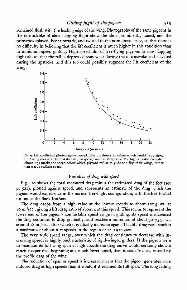
The maximum lift coefficient in gliding is about 1-3. Since wing area decreases withspeed, the lift coefficient does not decline as rapidly as it otherwise would as speed isincreased, and reaches about 0-25 at the highest speeds tested (Fig. 9). If a rubber band

518 C. J. PENNYCUICK
was put round the tail to prevent its being spread, the maximum lift coefficient (stillbased on the sum of wing and tail areas) was reduced to i-2. Thus the tail, besidesproviding some lift, appears to augment the maximum lift coefficient of the wing whenfully spread.
650
600
550
500
450
400
350
150
100
50
70
60
50
40
30
20
7
6
5
4
3
2
1
(a).
(b)
i
. I '• •
(c)
-
-
• t
•
•
> • •
*
1 1
• •
10 12 14 16
Airspeed (m./sec.)
18 20 22
Fig. 8. Measurements of (a) wing area, (6) tail area, (c) wing span and(d) aspect ratio plotted against speed.
Pennycuick (1967), noting that pigeons can hover, calculated that a lift coefficient ofat least 3-4 would be required to account for this—an unduly high estimate, since noaccount was taken of downward induced velocity. When this is rectified, the estimatedlift coefficient in hovering is revised to 2-8, but this is still over twice the maximumobserved in gliding. There is no inconsistency in this, however, since pigeons donot stall at the minimum gliding speed obtainable in the wind tunnel, but merelyrefuse to glide, and start flapping their wings. Apart from full spreading of the tail,there is no obvious deployment of high-lift devices at the minimum gliding speed; inone pigeon the alula was raised about 1 mm at this speed, while in the others it
Gliding flight of the pigeon 519
remained flush with the leading edge of the wing. Photographs of the same pigeons inthe downstroke of slow flapping flight show the alula prominently raised, and theprimaries splayed, bent upwards, and twisted in the nose-down sense, so that there isno difficulty in believing that the lift coefficient is much higher in this condition thanin minimum-speed gliding. High-speed film of free-flying pigeons in slow flappingflight shows that the tail is depressed somewhat during the downstroke and elevatedduring the upstroke, and this too could possibly augment the lift coefficient of thewing.
1-41-
1-2
10
.§ o-8
0-6
0-4
02
8 10 12 14 16 18 20 22
Airspeed (m./sec.)
Fig. 9. Lift coefficient plotted against speed. The line shows the values which would be obtainedif the wing area were kept at its full (low speed) value at all speeds. The highest value recorded(about 1-3) marks the speed below which pigeons refuse to glide and flap their wings, ratherthan a true stalling speed.
Variation of drag with speed
Fig. 10 shows the total measured drag minus the estimated drag of the feet (seep. 521), plotted against speed, and represents an estimate of the drag which thepigeon would experience in the normal free-flight configuration, with the feet tuckedup under the flank feathers.
The drag drops from a high value at the lowest speeds to about 100 g. wt. at10 m./sec, giving a lift: drag ratio of about 4 at this speed. This seems to represent thelower end of the pigeon's comfortable speed range in gliding. As speed is increasedthe drag continues to drop gradually, and reaches a minimum of about 70-75 g. wt.around 18 m./sec, after which it gradually increases again. The lift:drag ratio reachesa maximum of about 6 at speeds in the region of 18-19 m./sec.
The very wide speed range, over which the drag continues to decrease with in-creasing speed, is highly uncharacteristic of rigid-winged gliders. If the pigeon wereto maintain its full wing span at high speeds the drag curve would certainly show amuch steeper rise, beginning at a much lower speed, than it actually does, caused bythe profile drag of the wing.
The reduction of span as speed is increased means that the pigeon generates moreinduced drag at high speeds than it would if it retained its full span. The long falling

520 C. J. PENNYCUICK
portion of the drag curve between 12 and 18 m./sec. must therefore imply thatshortening the wings at high speeds produces a reduction of wing profile drag, whichmore than offsets the increase in induced drag. This can be demonstrated by analysingthe total drag into various components.
cm2Q
150
100
50 -
l l i
•
•
•
. . •
* • : • * ' .. * • • •
i i i i i
•%
i i
•
i8 10 12 14 16 18 20 22
Airspeed (m./sec.)
Fig. 10. Total gliding drag, after subtracting the estimateddrag of the feet, plotted against speed.
Drag analysis
The total drag was measured directly (p. 510) and was assumed to be due to thefollowing four additive components:
(1) Body drag.(2) Foot drag.(3) Induced drag.(4) Wing profile drag.The drag of the body and feet were estimated from the results of supplementary
experiments, and the induced drag was calculated. Wing profile drag was assumed toaccount for the remainder of the total drag, and was estimated by subtracting the otherthree components from the total drag.
The estimation of the various drag components proceeded as follows.
Body drag
A feral pigeon was captured and killed by chloroforming, after which its wings wereremoved at the shoulder joint with as little disturbance as possible to the surroundingfeathers. The wingless body was frozen in the attitude shown in Fig. 11, with the feetretracted forward under the flank feathers in the normal free-flight position. The bodywas mounted on the end of a flat brass strip 4 cm. long and 0-15 cm. thick, whichcontinued as twin spikes inserted through the abdominal region. The whole was then

J
Gliding flight of the pigeon 521
mounted on the end of a length of \ in. brass tube as shown in Fig. 12, and supportedin the working section of the tunnel, which was set horizontal. The brass rod waspivoted, and the drag moment acting on it was measured by a horizontal springbalance, after preliminary experiments to determine the exact position of the pivot andthe zero error of the balance. The measured drag moment was corrected by subtractingthe drag moment of the pivoted bar, carrying a dummy mounting strip but no body.The corrected drag moment, divided by the distance from the pivot to the axis of thebody, gave the drag of the body.
Fig. i i . To estimate the drag of the body, a frozen, wingless body was mounted on the end ofa length of i in. brass tube (a), via a short length of flat brass strip (6), with chamfered edges.The latter continued as two sharpened prongs (c) on which the body was impaled.
Wind
V
Fig. 12. Diagram of the balance used for measuring the drag of parts of dead pigeons. The speci-men (a) was mounted as shown in Fig. 11 on one end of a length of i in. brass tubing pivotedin a ballrace at b, and restrained by the stop c. Several attachment points d were provided atdifferent distances from the pivot, and a spring balance e was attached to one of these to measurethe drag moment.
Fig. 13 shows the measured drag at a series of speeds from 8 to 20 m./sec. Themaximum frontal area of the body was 36 cm.2, and the drag coefficient, based on thisarea, averaged 0-43. The drag coefficient showed no tendency to change progressivelywith speed, the extreme values being 0-42 at 12 m./sec. and 0-46 at 8 m./sec.
Foot drag
Unlike the body drag, the drag of the feet is under the control of the bird. The feetare used to adjust the gliding angle in rather the same way as the airbrakes of a glider,and are in constant use for fine control of position when a pigeon flies in the tunnel.(P-

522 C. J. PENNYCUICK
In free flight the ankle joints are normally flexed, so that the tarsi and feet comeforward, and are completely covered by the flank feathers (Fig. 4). In this position thefeet would presumably contribute little or no drag. When a small amount of additionaldrag is required, the tarsal joints are extended, and the feet are carried, with the toesfurled, beneath the tail (Fig. 4). From this position, airbrake action is quickly obtainedby lowering the feet and spreading the toes (Fig. 4).
) 2 4 6 8 10 12 14 16 18 20
Airspeed (m./sec.)
Fig. 13. Measured drag of a wingless body, plotted against speed.
Fig. 14. Pigeons' feet fixed in formalin and mounted as shown in Fig. 12 for drag measurements,(a) with toes fully spread, and (6) with toes furled. Drag coefficients were calculated from frontalareas as seen in this view.
To estimate foot drag, the feet of a freshly killed pigeon were cut off just above theankle joint and fixed in 10% formalin for a fortnight. During fixing, one foot waspinned in the fully spread position (Fig. 14a) and the other as shown in Fig. 146.When sufficiently rigid, the feet were mounted in the end of the pivoted brass tube(Fig. 12), and their drag was measured by the same method as was used for body drag.The results are plotted in Fig. 15.
Gliding flight of the pigeon 523
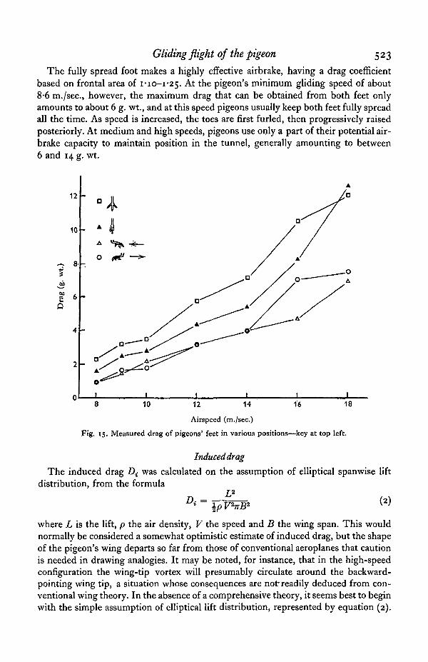
The fully spread foot makes a highly effective airbrake, having a drag coefficientbased on frontal area of I - I O - I ^ . At the pigeon's minimum gliding speed of about8-6 m./sec, however, the maximum drag that can be obtained from both feet onlyamounts to about 6 g. wt., and at this speed pigeons usually keep both feet fully spreadall the time. As speed is increased, the toes are first furled, then progressively raisedposteriorly. At medium and high speeds, pigeons use only a part of their potential air-brake capacity to maintain position in the tunnel, generally amounting to between6 and 14 g. wt.
12
10
CQ O
8 10 16 1812 14
Airspeed (m./sec.)
Fig. 15. Measured drag of pigeons' feet in various positions—key at top left.
Induceddrag
The induced drag Di was calculated on the assumption of elliptical spanwise liftdistribution, from the formula
L2
Di = \p V*nB2 ^
where L is the lift, p the air density, V the speed and B the wing span. This wouldnormally be considered a somewhat optimistic estimate of induced drag, but the shapeof the pigeon's wing departs so far from those of conventional aeroplanes that cautionis needed in drawing analogies. It may be noted, for instance, that in the high-speedconfiguration the wing-tip vortex will presumably circulate around the backward-pointing wing tip, a situation whose consequences are not'readily deduced from con-ventional wing theory. In the absence of a comprehensive theory, it seems best to beginwith the simple assumption of elliptical lift distribution, represented by equation (2).

524 C. J. PENNYCUICK
It is unlikely that the true induced drag would be less than the calculated value, but itcould be higher if the lift distribution were other than elliptical.
Fig. 16 a shows the calculated induced drag plotted against speed. The line showsthe curve which would be obtained if the wing span were kept constant at 65 cm.It can be seen that the pigeon will not glide at very low speeds, where the induced dragwould increase sharply, but starts flapping its wings below about 8-6 m./sec. At speedsabove about 11 m./sec, wing span starts to be reduced, causing an increase in induceddrag above the dotted line. At high speeds the induced drag rises to about 20-25 g. wt.as wing span is progressively reduced.
120 -
110 -
100
90
80
? 70
-2Sso2Q
60
50
40
30
20
10
8 10 12 14 16 18 20 22
Airspeed (m./sec.)
Fig. 16. (a) Circles—estimated induced drag. The line shows the values which would be obtainedif the span remained constant at its maximum (low speed) value. (6) Triangles. Wing profiledrag, estimated by subtracting other components from the measured total drag.
Wing profile drag
The wing profile drag, obtained by subtraction as explained on p. 510, shows a verymarked decrease with speed. The present assumptions imply that the high drag ob-served at low gliding speeds (Fig. 10) consists mainly of wing profile drag, not of induceddrag as would at first sight appear. This conclusion might, of course, have to be revisedif subsequent investigation were to show that the induced drag is much higher thanhas been assumed; the error would, however, have to be improbably large to invalidatethe main conclusions, since the wing profile drag, as calculated here, is about threetimes the induced drag at low speeds. Wing profile drag and induced drag meet in theregion of 20-30 g. wt at speeds of about 17-18 m./sec.
The very low values of wing profile drag calculated for speeds above 18 m./sec. shouldbe regarded with reserve because of doubts inherent in the subtractive method of

Gliding flight of the pigeon 525
calculation. In particular, foot drag becomes more and more sensitive to small changesof foot position as speed is increased, and any errors made in estimating this com-ponent are reflected in the estimated wing profile drag.
DISCUSSION
The general nature of the planform changes associated with speed (pp. 516-517)has been known since the observations of Hankin (1913) on vultures (Aegypiinae) andother gliding birds. Pennycuick & Webbe (1959) observed these changes in glidingfulmars (Fulmarus glacialis) and interpreted them as being simultaneously (a) controlmovements, bringing about changes of longitudinal trim needed in speed control, and(b) an adaptation to good ' penetration', that is the ability to glide over a wide range ofspeeds without serious deterioration of the gliding angle, which is an important con-sideration in soaring. The latter aspect is put into quantitative form for the pigeon inFig. 16, and depends on the bird's ability to reduce its wing area by increasing theamount of overlap of the feathers.
Bats would presumably not be able to control their wing area to the same extent.They have muscle fibres in the patagium which can reduce its area at the expense ofcrinkling the skin, but it seems hardly likely that a planform approaching that shownin Fig. jc would be possible in a bat. This may be one reason why bats have apparentlynever been recorded soaring (Felten, i960).
SUMMARY
1. A technique for training pigeons to fly in a tilting wind tunnel is described, and amethod of determining lift and drag in gliding flight is explained.
2. Drag measurements were made on wingless bodies and preserved feet in supple-mentary experiments. The results were used to analyse the measured total drag of livepigeons into (a) body drag, (b) foot drag, (c) induced drag, and (d) wing profile drag.
3. As speed is increased, gliding pigeons drastically reduce their wing span, wingarea and aspect ratio. The increased induced drag resulting from this is more thanoffset by a very large reduction in wing profile drag.
4. Although the lift:drag ratio is at best 5-5-6-0, changes of wing area and shapekeep it near its maximum, up to speeds at least twice the minimum gliding speed.
The construction of the wind tunnel was financed by a grant from the ScienceResearch Council, and I am extremely grateful to that body, and to the late Prof. J. E.Harris, F.R.S. for backing the project before it could be proved that the techniquewould work. I am deeply indebted to members of the Department of AeronauticalEngineering of the University of Bristol for continual help and advice throughout thedesign construction and testing of the wind tunnel, especially to Mr T. V. Lawson,Dr J. Tinkler and Mr J. Flower. I am also most grateful for substantial amountsof manual labour contributed during construction, principally by Dr D. R. Jones,Mr D. Curry and my wife.
34 Exp. Biol. 49, 3

526 C. J. PENNYCUICK
REFERENCES
FELTEN, H. (i960). Fliegende Saugetiere. In H. Schmidt (Ed.) Der Flug der Tiere, pp. 113-34. Frank-furt: Kramer.
GREENEWALT, C. H. (1961). Hummingbirds. New York: Doubleday.HANKIN, E. H. (1913). Animal Flight: A Record of Observation. London.PANKHURST, R. C. & HOLDER, D. W. (1965). Wind Tunnel Technique. London: Pitman.PENNYCUICK, C. J. (1967). The strength of the pigeon's wing bones in relation to their function. J. exp.
Biol. 46, 219-33.PENNYCUICK, C. J. & WEBBE, D. (1959). Observations on the fulmar in Spitsbergen. Brit. Birds 52,
321-32-RASPET, A. (1950). Performance measurements of a soaring bird. Aeronaut etigng Rev. 9, no. 12, 14-17.TUCKER, V. A. (1968). Respiratory exchange and evaporative water loss in the flying budgerigar, jf. exp.
Biol. 48, 67-87.