Embed Size (px)
Citation preview
Software & Systems Modeling manuscript No.(will be inserted by the editor)
A Visual Language for Modeling MultiplePerspectives of Business Process Compliance Rules
David Knuplesch and Manfred Reichert
Received: 8 October 2014 / Revised: 21 December 2015 / Accepted: 3 March 2016
Abstract A fundamental challenge for enterprises is to ensure compliance oftheir business processes with imposed compliance rules stemming from varioussources, e.g., corporate guidelines, best practices, standards, and laws. In gen-eral, a compliance rule may refer to multiple process perspectives includingcontrol flow, time, data, resources, and interactions with business partners.On one hand, compliance rules should be comprehensible for domain expertswho must define, verify and apply them. On the other, these rules should havea precise semantics to avoid ambiguities and enable their automated process-ing. Providing a visual language is advantageous in this context as it allowshiding formal details and offering an intuitive way of modeling the compli-ance rules. However, existing visual languages for compliance rule modelinghave focused on the control flow perspective so far, but lack proper supportfor the other process perspectives. To remedy this drawback, this paper in-troduces the extended Compliance Rule Graph language, which enables thevisual modeling of compliance rules with the support of multiple perspectives.Overall, this language will foster the modeling and verification of compliancerules in practice.
Keywords business process compliance, extended compliance rule graphs,business process modeling, smart processes
1 Introduction
During the last decades a variety of techniques for verifying the correctnessof business process models were proposed. While early approaches focused on
David Knuplesch and Manfred ReichertUlm University,Institute of Database and Information SystemsJames-Franck-Ring89081 Ulm, GermanyE-mail: [email protected]
2 David Knuplesch and Manfred Reichert
issues related to structural and behavioral model correctness (e.g., absenceof deadlocks and livelocks) [1,84], the semantic correctness of process modelswith respect to imposed compliance rules (i.e., business process compliance)has been subject to recent works [34,65,10,45]. Compliance rules constrainthe execution order (i.e. control flow) of tasks and may originate, for exam-ple, from security constraints, domain-specific guidelines, corporate standards,and legal regulations. Besides the control flow perspective, other fundamentalperspectives1 relevant in the context of business process compliance refer totime, data, and resources as well as the interactions a business process haswith partner processes [20,81,51].
1.1 Problem Statement
In practice, compliance rules are represented in a rather verbose and am-biguous way. To enable the computer-based verification of business processcompliance, i.e., to verify that a particular business process meets imposedcompliance rules, subject matter experts and business analysts should provideunambiguous descriptions of compliance rules, which then can be translatedinto a machine-readable representation by IT experts. For the latter purpose,several approaches for the formal specification of compliance rules exist, e.g.applying linear temporal logics (LTL) [30] or using the formal contract lan-guage (FCL) [33]. As formal rule languages would be too intricate for subjectmatter experts and business analysts, rule patterns hiding formal details andproviding informal explanations were suggested [24,97,80,82]. Although fewapproaches exist that not only consider the control flow perspective, but alsothe data, time and resource perspectives, these approaches only support apre-specified set of rule patterns.
As shown by empirical studies, business process modeling as well as com-pliance rule description languages, which both employ visual notations, offeradvantages compared to purely text-based specifications [77,38]: First, visualnotations significantly increase model and rule comprehensibility after pro-viding some training to users. Second, they foster the communication amongbusiness analysts and subject matter experts on one hand and process en-gineers on the other. As a prequisite for the computerized support of visualspecifications, the latter should be machine-readable, relying on a precise for-mal semantics.
Examples of visual notations for compliance rules include Compliance RuleGraphs [66], BPMN-Q [9], and BPSL [62]. Like visual process modeling lan-guages (e.g., YAWL [3], ADEPT [85] and BPMN [75])2, theses approaches
1 In this paper, the notion of process perspective corresponds to a specific business processmodeling dimension according to [17].
2 Note that imperative process modeling approaches tend to (over-)specify business pro-cesses. Hence, they are not well suited for specifying declarative constraints and processcompliance rules [79,35,87].
A Visual Language for Modeling Business Process Compliance Rules 3
combine an intuitive notation with the advantages of a formal language. Ex-isting visual compliance rule languages, however, lack a comprehensive supportof the time, data, resource, and interaction perspectives of a business processes,which hinders their use in more sophisticated scenarios.
1.2 Contribution
Although there exist pattern-based approaches for modeling compliance rulesalso covering the time, data, and resource perspectives, a respective visualmodeling support has not been provided so far [80,97]. To remedy this draw-back, this paper provides an approach for the visual modeling of compliancerules that may refer to these perspectives as well as to the interactions a busi-ness process may have with partner processes. In particular, the paper showshow the various perspectives can be visually represented with the extendedCompliance Rule Graph (eCRG) language. We evaluate the expressiveness ofthe latter based on well-known patterns and apply the eCRG language to areal-world healthcare scenario. Furthermore, understandability issues are con-sidered in an empirical study. Finally, we present a proof-of-concept prototypethat supports the modeling of eCRGs as well as their verification. The latteris based on a profound formal semantics of the eCRGs, which is provided ina technical report [49]. Altogether, the eCRG language allows domain expertsto capture compliance requirements at both an abstract and a visual level,while enabling the specification of verifiable compliance rules that considerthe various perspectives.
This paper significantly extends our previous work, which introduced fun-damentals of the eCRG language [50,94]: In [50], we provided a very briefoverview of the eCRG language, whereas in [94] we focused on the resourceperspective solely. In addition to these preliminary works, this paper provides
– the first detailed presentation of the eCRG elements covering the interac-tion, time, data, and resource perspectives,
– an empirical study on the comprehensibility of the eCRG language– a proof-of-concept prototype, which comprises a modeling environment as
well as an eCRG compliance checker verifying the compliance of givenprocess execution logs with a set of eCRGs, and
– an extended and more profound discussion of related work.
The remainder of the paper is organized as follows: Section 2 provides anapplication scenario from the healthcare domain, which we will use as illus-trating example throughout the paper. In Section 3, we introduce the eCRGlanguage step-by-step. Specifically, this language supports the visual model-ing of compliance rules that may refer to the control flow, interaction, time,data, and resource perspectives. To assess the approach, Section 4 provides apattern-based evaluation and demonstrates the modeling of real-world com-pliance rules with the eCRG language. Furthermore, it presents an empiricalstudy and the proof-of-concept prototype we developed. Related Work is dis-
4 David Knuplesch and Manfred Reichert
cussed in Section 5. Section 6 concludes the paper and provides an outlook onfuture work.
2 Application Scenario
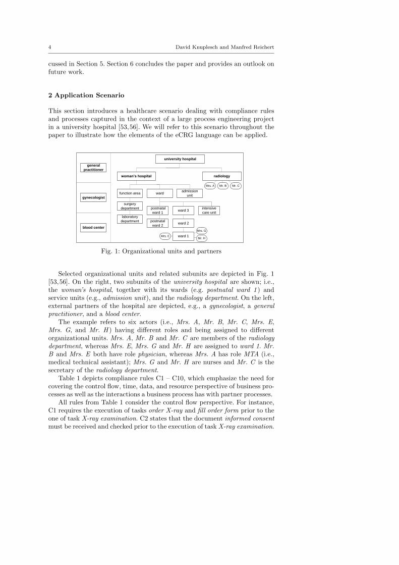
This section introduces a healthcare scenario dealing with compliance rulesand processes captured in the context of a large process engineering projectin a university hospital [53,56]. We will refer to this scenario throughout thepaper to illustrate how the elements of the eCRG language can be applied.
woman’s hospital
general
practitioner
radiology
function area
gynecologist
admission
unitward
postnatal
ward 1ward 3
ward 2
ward 1
postnatal
ward 2
surgery
department
laboratory
department
university hospital
blood center
intensive
care unit
Mrs. A Mr. B Mr. C
Mrs. G
Mr. HMrs. E
Fig. 1: Organizational units and partners
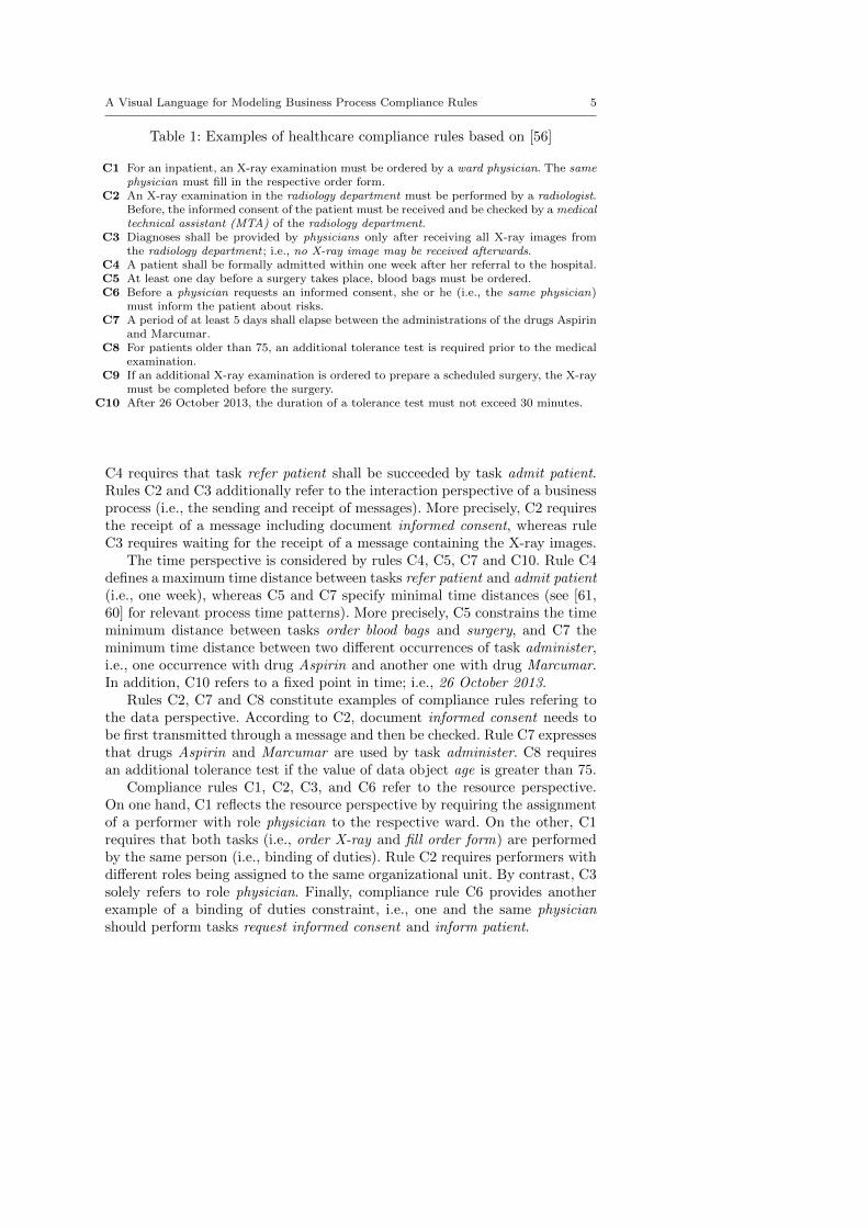
Selected organizational units and related subunits are depicted in Fig. 1[53,56]. On the right, two subunits of the university hospital are shown; i.e.,the woman’s hospital, together with its wards (e.g. postnatal ward 1 ) andservice units (e.g., admission unit), and the radiology department. On the left,external partners of the hospital are depicted, e.g., a gynecologist, a generalpractitioner, and a blood center.
The example refers to six actors (i.e., Mrs. A, Mr. B, Mr. C, Mrs. E,Mrs. G, and Mr. H ) having different roles and being assigned to differentorganizational units. Mrs. A, Mr. B and Mr. C are members of the radiologydepartment, whereas Mrs. E, Mrs. G and Mr. H are assigned to ward 1. Mr.B and Mrs. E both have role physician, whereas Mrs. A has role MTA (i.e.,medical technical assistant); Mrs. G and Mr. H are nurses and Mr. C is thesecretary of the radiology department.
Table 1 depicts compliance rules C1 – C10, which emphasize the need forcovering the control flow, time, data, and resource perspective of business pro-cesses as well as the interactions a business process has with partner processes.
All rules from Table 1 consider the control flow perspective. For instance,C1 requires the execution of tasks order X-ray and fill order form prior to theone of task X-ray examination. C2 states that the document informed consentmust be received and checked prior to the execution of task X-ray examination.
A Visual Language for Modeling Business Process Compliance Rules 5
Table 1: Examples of healthcare compliance rules based on [56]
C1 For an inpatient, an X-ray examination must be ordered by a ward physician. The samephysician must fill in the respective order form.
C2 An X-ray examination in the radiology department must be performed by a radiologist.Before, the informed consent of the patient must be received and be checked by a medicaltechnical assistant (MTA) of the radiology department.
C3 Diagnoses shall be provided by physicians only after receiving all X-ray images fromthe radiology department ; i.e., no X-ray image may be received afterwards.
C4 A patient shall be formally admitted within one week after her referral to the hospital.C5 At least one day before a surgery takes place, blood bags must be ordered.C6 Before a physician requests an informed consent, she or he (i.e., the same physician)
must inform the patient about risks.C7 A period of at least 5 days shall elapse between the administrations of the drugs Aspirin
and Marcumar.C8 For patients older than 75, an additional tolerance test is required prior to the medical
examination.C9 If an additional X-ray examination is ordered to prepare a scheduled surgery, the X-ray
must be completed before the surgery.C10 After 26 October 2013, the duration of a tolerance test must not exceed 30 minutes.
C4 requires that task refer patient shall be succeeded by task admit patient.Rules C2 and C3 additionally refer to the interaction perspective of a businessprocess (i.e., the sending and receipt of messages). More precisely, C2 requiresthe receipt of a message including document informed consent, whereas ruleC3 requires waiting for the receipt of a message containing the X-ray images.
The time perspective is considered by rules C4, C5, C7 and C10. Rule C4defines a maximum time distance between tasks refer patient and admit patient(i.e., one week), whereas C5 and C7 specify minimal time distances (see [61,60] for relevant process time patterns). More precisely, C5 constrains the timeminimum distance between tasks order blood bags and surgery, and C7 theminimum time distance between two different occurrences of task administer,i.e., one occurrence with drug Aspirin and another one with drug Marcumar.In addition, C10 refers to a fixed point in time; i.e., 26 October 2013.
Rules C2, C7 and C8 constitute examples of compliance rules refering tothe data perspective. According to C2, document informed consent needs tobe first transmitted through a message and then be checked. Rule C7 expressesthat drugs Aspirin and Marcumar are used by task administer. C8 requiresan additional tolerance test if the value of data object age is greater than 75.
Compliance rules C1, C2, C3, and C6 refer to the resource perspective.On one hand, C1 reflects the resource perspective by requiring the assignmentof a performer with role physician to the respective ward. On the other, C1requires that both tasks (i.e., order X-ray and fill order form) are performedby the same person (i.e., binding of duties). Rule C2 requires performers withdifferent roles being assigned to the same organizational unit. By contrast, C3solely refers to role physician. Finally, compliance rule C6 provides anotherexample of a binding of duties constraint, i.e., one and the same physicianshould perform tasks request informed consent and inform patient.
6 David Knuplesch and Manfred Reichert
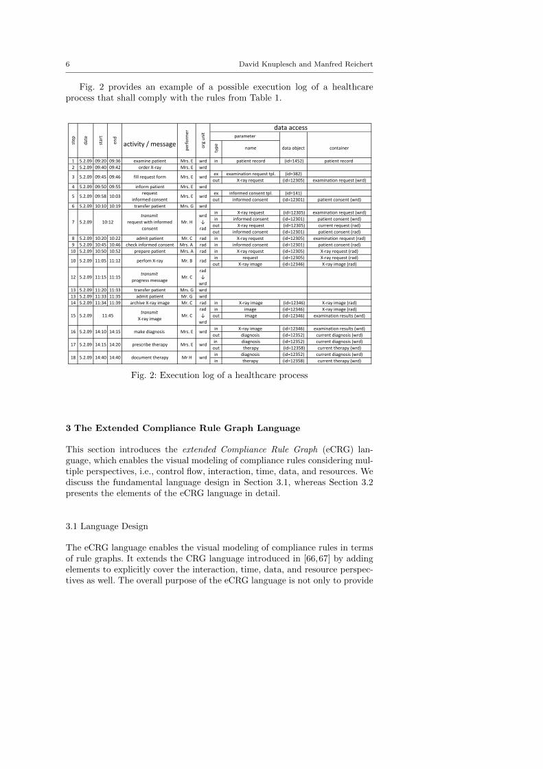
Fig. 2 provides an example of a possible execution log of a healthcareprocess that shall comply with the rules from Table 1.
type ,
name
1 5.2.09 09:20 09:36 examine patient Mrs. E wrd in patient record (id=1452) patient record
2 5.2.09 09:40 09:42 order X‐ray Mrs. E wrd
ex examination request tpl. (id=382)
out X‐ray request (id=12305) examination request (wrd)
4 5.2.09 09:50 09:55 inform patient Mrs. E wrd
ex informed consent tpl. (id=141)
out informed consent (id=12301) patient consent (wrd)
6 5.2.09 10:10 10:19 transfer patient Mrs. G wrd
in X‐ray request (id=12305) examination request (wrd)
in informed consent (id=12301) patient consent (wrd)
out X‐ray request (id=12305) current request (rad)
out informed consent (id=12301) patient consent (rad)
8 5.2.09 10:20 10:22 admit patient Mr. C rad in X‐ray request (id=12305) examination request (rad)
9 5.2.09 10:45 10:46 check informed consent Mrs. A rad in informed consent (id=12301) patient consent (rad)
10 5.2.09 10:50 10:52 prepare patient Mrs. A rad in X‐ray request (id=12305) X‐ray request (rad)
in request (id=12305) X‐ray request (rad)
out X‐ray image (id=12346) X‐ray image (rad)
12 5.2.09 11:15 11:15transmit
progress messageMr. C
rad
↓
wrd
13 5.2.09 11:20 11:33 transfer patient Mrs. G wrd
13 5.2.09 11:33 11:35 admit patient Mr. G wrd
14 5.2.09 11:34 11:39 archive X‐ray image Mr. C rad in X‐ray image (id=12346) X‐ray image (rad)
in image (id=12346) X‐ray image (rad)
out image (id=12346) examination results (wrd)
in X‐ray image (id=12346) examination results (wrd)
out diagnosis (id=12352) current diagnosis (wrd)
in diagnosis (id=12352) current diagnosis (wrd)
out therapy (id=12358) current therapy (wrd)
in diagnosis (id=12352) current diagnosis (wrd)
in therapy (id=12358) current therapy (wrd)wrd
container
data access
18 5.2.09 14:40 14:40 document therapy Mr H
wrd
17 5.2.09 14:15 14:20 prescribe therapy Mrs. E wrd
16 5.2.09 14:10 14:15 make diagnosis Mrs. E
rad
15 5.2.09 11:45transmit
X‐ray image Mr. C
rad
↓
wrd
10 5.2.09 11:05 11:12 perfom X‐ray Mr. B
wrd
↓
rad
wrd
5 5.2.09 09:58 10:03request
informed consentMrs. E wrd
7 5.2.09 10:12
transmit
request with informed
consent
Mr. H
org unit parameter
data object
3 5.2.09 09:45 09:46 fill request form Mrs. E
step
date
start
end
activity / message
perform
er
Fig. 2: Execution log of a healthcare process
3 The Extended Compliance Rule Graph Language
This section introduces the extended Compliance Rule Graph (eCRG) lan-guage, which enables the visual modeling of compliance rules considering mul-tiple perspectives, i.e., control flow, interaction, time, data, and resources. Wediscuss the fundamental language design in Section 3.1, whereas Section 3.2presents the elements of the eCRG language in detail.
3.1 Language Design
The eCRG language enables the visual modeling of compliance rules in termsof rule graphs. It extends the CRG language introduced in [66,67] by addingelements to explicitly cover the interaction, time, data, and resource perspec-tives as well. The overall purpose of the eCRG language is not only to provide
A Visual Language for Modeling Business Process Compliance Rules 7
a well-defined visual language, but to provide a tool fostering the communica-tion between IT experts on one side and domain experts on the other.
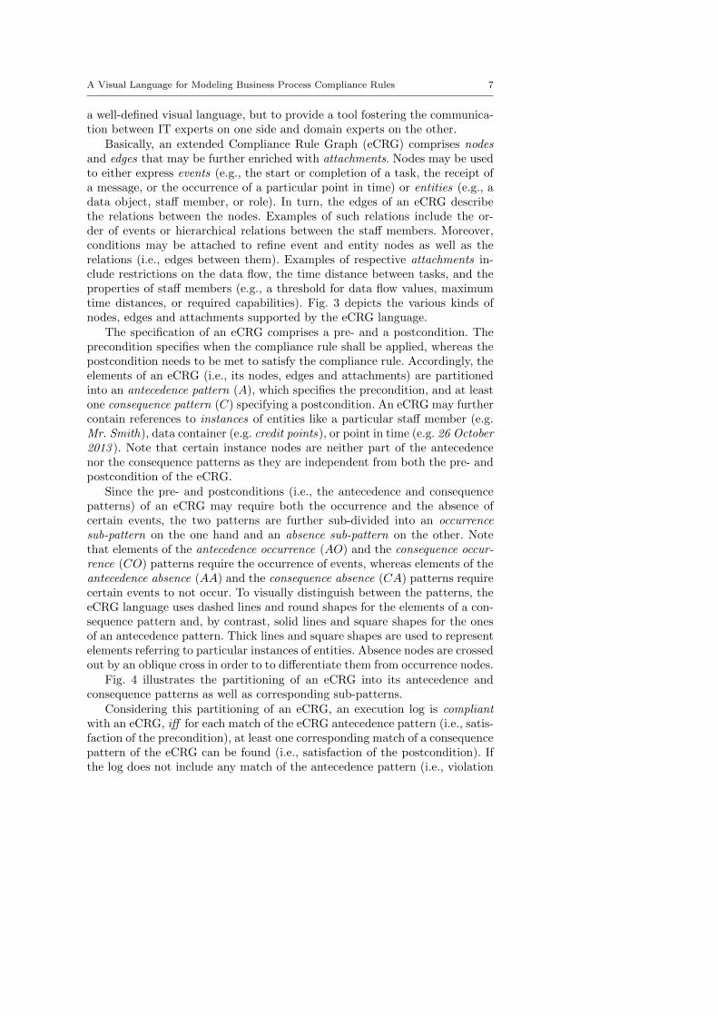
Basically, an extended Compliance Rule Graph (eCRG) comprises nodesand edges that may be further enriched with attachments. Nodes may be usedto either express events (e.g., the start or completion of a task, the receipt ofa message, or the occurrence of a particular point in time) or entities (e.g., adata object, staff member, or role). In turn, the edges of an eCRG describethe relations between the nodes. Examples of such relations include the or-der of events or hierarchical relations between the staff members. Moreover,conditions may be attached to refine event and entity nodes as well as therelations (i.e., edges between them). Examples of respective attachments in-clude restrictions on the data flow, the time distance between tasks, and theproperties of staff members (e.g., a threshold for data flow values, maximumtime distances, or required capabilities). Fig. 3 depicts the various kinds ofnodes, edges and attachments supported by the eCRG language.
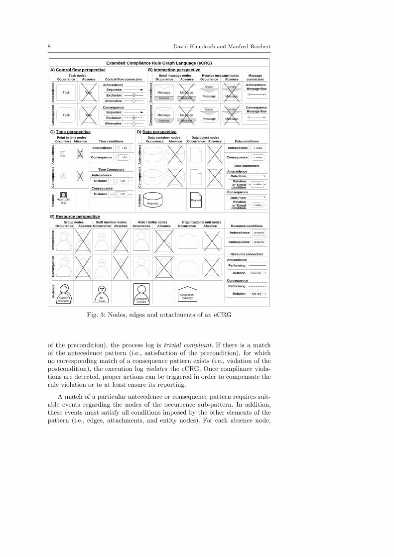
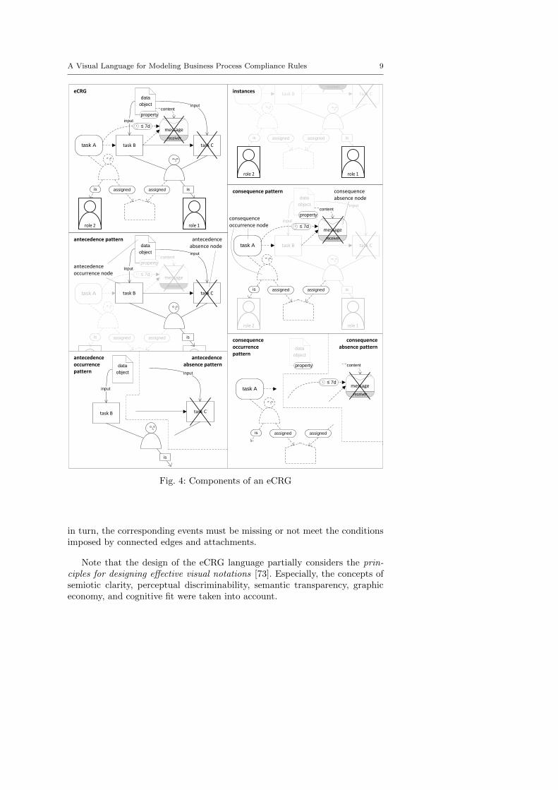
The specification of an eCRG comprises a pre- and a postcondition. Theprecondition specifies when the compliance rule shall be applied, whereas thepostcondition needs to be met to satisfy the compliance rule. Accordingly, theelements of an eCRG (i.e., its nodes, edges and attachments) are partitionedinto an antecedence pattern (A), which specifies the precondition, and at leastone consequence pattern (C) specifying a postcondition. An eCRG may furthercontain references to instances of entities like a particular staff member (e.g.Mr. Smith), data container (e.g. credit points), or point in time (e.g. 26 October2013 ). Note that certain instance nodes are neither part of the antecedencenor the consequence patterns as they are independent from both the pre- andpostcondition of the eCRG.
Since the pre- and postconditions (i.e., the antecedence and consequencepatterns) of an eCRG may require both the occurrence and the absence ofcertain events, the two patterns are further sub-divided into an occurrencesub-pattern on the one hand and an absence sub-pattern on the other. Notethat elements of the antecedence occurrence (AO) and the consequence occur-rence (CO) patterns require the occurrence of events, whereas elements of theantecedence absence (AA) and the consequence absence (CA) patterns requirecertain events to not occur. To visually distinguish between the patterns, theeCRG language uses dashed lines and round shapes for the elements of a con-sequence pattern and, by contrast, solid lines and square shapes for the onesof an antecedence pattern. Thick lines and square shapes are used to representelements referring to particular instances of entities. Absence nodes are crossedout by an oblique cross in order to to differentiate them from occurrence nodes.
Fig. 4 illustrates the partitioning of an eCRG into its antecedence andconsequence patterns as well as corresponding sub-patterns.
Considering this partitioning of an eCRG, an execution log is compliantwith an eCRG, iff for each match of the eCRG antecedence pattern (i.e., satis-faction of the precondition), at least one corresponding match of a consequencepattern of the eCRG can be found (i.e., satisfaction of the postcondition). Ifthe log does not include any match of the antecedence pattern (i.e., violation
8 David Knuplesch and Manfred Reichert
March 23th
2013
An
tec
ed
en
ce
Co
ns
eq
ue
nc
e
Occurrence Absence
Task
TaskTask
Extended Compliance Rule Graph Language (eCRG)
A) Control flow perspective
Occurrence Absence Occurrence Absence
Sender
ReceiverMessage
Message
Sender
Message
Sender
ReceiverMessage
Message
Sender
Message
Receiver
Message
Receive message nodesSend message nodes
An
tec
ed
en
ce
Co
ns
eq
ue
nc
e
B) Interaction perspective
Sequence
Exclusion
Antecedence
Alternative
Control flow connectors
Sequence
Exclusion
Consequence
Alternative
X
X
Task
Receiver
Message
Task nodes
Data object nodesA
nte
ce
de
nc
eC
on
se
qu
en
ce
Requests
Request
Ins
tan
ce
D) Data perspective
< value
> value
Data conditions
Data connectors
Data Flow
Antecedence
Data Flow
Consequence
Group nodes
E) Resource perspective
An
tec
ed
en
ce
Co
ns
eq
ue
nc
eIn
sta
bc
e
Mr.
Smith
Computer
scientist
Quality
managers
Department
radiology
property
propertyAntecedence
Consequence
Resource conditions
Resource connectors
Performing
Relation
Antecedence
has role
Relation
Consequence
has role
AbsenceOccurrence Absence AbsenceOccurrence AbsenceOccurrence
Staff member nodes Role / ability nodes Organizational unit nodes
Occurrence Absence Occurrence Absence
Data container nodes
Occurrence Absence
Point in time nodes
Antecedence
Consequence
An
tec
ed
en
ce
Co
ns
eq
ue
nc
eIn
sta
nc
e
Time conditions
>2d
>2d
Antecedence
Consequence
Time Connectors
Distance
Antecedence
Distance
Consequence
>2d
>2d
Performing
or Timed condition
or Timed condition
Occurrence
C) Time perspective
Antecedence
Consequence
connectors
Message
Message flow
Message flow
> value
< valueRelation
Relation
Fig. 3: Nodes, edges and attachments of an eCRG
of the precondition), the process log is trivial compliant. If there is a matchof the antecedence pattern (i.e., satisfaction of the precondition), for whichno corresponding match of a consequence pattern exists (i.e., violation of thepostcondition), the execution log violates the eCRG. Once compliance viola-tions are detected, proper actions can be triggered in order to compensate therule violation or to at least ensure its reporting.
A match of a particular antecedence or consequence pattern requires suit-able events regarding the nodes of the occurrence sub-pattern. In addition,these events must satisfy all conditions imposed by the other elements of thepattern (i.e., edges, attachments, and entity nodes). For each absence node,
A Visual Language for Modeling Business Process Compliance Rules 9
task C task Btask A
receiver
message
role 1
role 2
task C task B
is
role 1
assigned
input
data
object input
task A
is
role 2
assigned
content
receiver
message
task C task B
assigned
input
data
object input
task A
is assigned
content
receiver
message
is
task C task B
is
role 1
assigned
input
data
object input
task A
is
role 2
assigned
content
receiver
message
antecedence pattern
consequence pattern consequence absence node
consequence occurrence node
antecedenceabsence node
antecedence occurrence node
≤ 7d
≤ 7d
≤ 7d
task B
input
data
object
is
task C
antecedence occurrence pattern
antecedence absence pattern content
receiver
message ≤ 7d
assigned
task A
is assigned
consequence occurrence pattern
consequence absence pattern
property
data
object
property
property
property
is
role 1
assigned
is
role 2
assigned
instances
input
eCRG
Fig. 4: Components of an eCRG
in turn, the corresponding events must be missing or not meet the conditionsimposed by connected edges and attachments.
Note that the design of the eCRG language partially considers the prin-ciples for designing effective visual notations [73]. Especially, the concepts ofsemiotic clarity, perceptual discriminability, semantic transparency, graphiceconomy, and cognitive fit were taken into account.
10 David Knuplesch and Manfred Reichert
3.2 eCRG Modeling
This section shows how the different process perspectives can be modeled withthe eCRG language. For each perspective, we first introduce the correspondingeCRG elements before illustrating their semantics along simple examples.
3.2.1 Control Flow Perspective
A fundamental process perspective of
An
tec
ed
en
ce
Co
ns
eq
ue
nc
e
Occurrence Absence
Task
TaskTask
Control flow perspective
Sequence
Exclusion
Antecedence
Alternative
Control flow connectors
Sequence
Exclusion
Consequence
Alternative
X
X
Task
Task nodes
Fig. 5: eCRG elements coveringthe control flow perspective
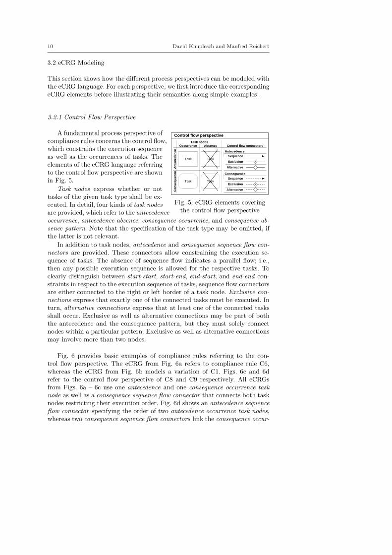
compliance rules concerns the control flow,which constrains the execution sequenceas well as the occurrences of tasks. Theelements of the eCRG language referringto the control flow perspective are shownin Fig. 5.
Task nodes express whether or nottasks of the given task type shall be ex-ecuted. In detail, four kinds of task nodesare provided, which refer to the antecedenceoccurrence, antecedence absence, consequence occurrence, and consequence ab-sence pattern. Note that the specification of the task type may be omitted, ifthe latter is not relevant.
In addition to task nodes, antecedence and consequence sequence flow con-nectors are provided. These connectors allow constraining the execution se-quence of tasks. The absence of sequence flow indicates a parallel flow; i.e.,then any possible execution sequence is allowed for the respective tasks. Toclearly distinguish between start-start, start-end, end-start, and end-end con-straints in respect to the execution sequence of tasks, sequence flow connectorsare either connected to the right or left border of a task node. Exclusive con-nections express that exactly one of the connected tasks must be executed. Inturn, alternative connections express that at least one of the connected tasksshall occur. Exclusive as well as alternative connections may be part of boththe antecedence and the consequence pattern, but they must solely connectnodes within a particular pattern. Exclusive as well as alternative connectionsmay involve more than two nodes.
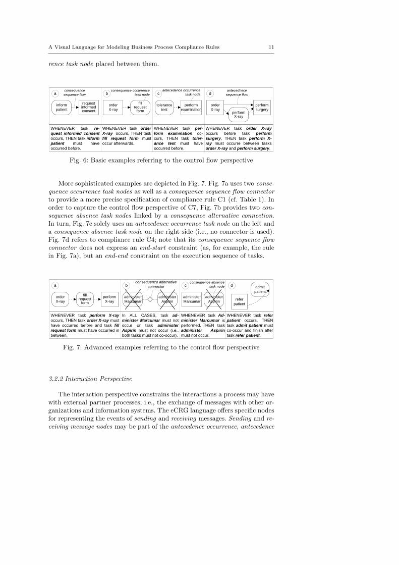
Fig. 6 provides basic examples of compliance rules referring to the con-trol flow perspective. The eCRG from Fig. 6a refers to compliance rule C6,whereas the eCRG from Fig. 6b models a variation of C1. Figs. 6c and 6drefer to the control flow perspective of C8 and C9 respectively. All eCRGsfrom Figs. 6a – 6c use one antecedence and one consequence occurrence tasknode as well as a consequence sequence flow connector that connects both tasknodes restricting their execution order. Fig. 6d shows an antecedence sequenceflow connector specifying the order of two antecedence occurrence task nodes,whereas two consequence sequence flow connectors link the consequence occur-
A Visual Language for Modeling Business Process Compliance Rules 11
rence task node placed between them.
order
X-ray
fillrequest
form performX-ray
perform
surgery
b c d
WHENEVER task order X-ray
occurs before task perform
surgery, THEN task perform X-
ray must occurre between tasks
order X-ray and perform surgery.
WHENEVER task order
X-ray occurs, THEN task
fill request form must
occur afterwards.
tolerance
test
perform
examination
WHENEVER task per-
form examination oc-
curs, THEN task toler-
ance test must have
occurred before.
inform
patient
requestinformed consent
WHENEVER task re-
quest informed consent
occurs, THEN task inform
patient must have
occurred before.
aantecedence occurrence
task nodeconsequence occurrence
task node
consequence
sequence flow
order
X-ray
antecednece
sequence flow
Fig. 6: Basic examples referring to the control flow perspective
More sophisticated examples are depicted in Fig. 7. Fig. 7a uses two conse-quence occurrence task nodes as well as a consequence sequence flow connectorto provide a more precise specification of compliance rule C1 (cf. Table 1). Inorder to capture the control flow perspective of C7, Fig. 7b provides two con-sequence absence task nodes linked by a consequence alternative connection.In turn, Fig. 7c solely uses an antecedence occurrence task node on the left anda consequence absence task node on the right side (i.e., no connector is used).Fig. 7d refers to compliance rule C4; note that its consequence sequence flowconnector does not express an end-start constraint (as, for example, the rulein Fig. 7a), but an end-end constraint on the execution sequence of tasks.
order
X-ray
fill request
form
perform
X-ray
a
WHENEVER task perform X-ray
occurs, THEN task order X-ray must
have occurred before and task fill
request form must have occurred in
between.
administer
Aspirin
administer
Marcumar
In ALL CASES, task ad-
minister Marcumar must not
occur or task administer
Aspirin must not occur (i.e.,
both tasks must not co-occur).
WHENEVER task Ad-
minister Marcumar is
performed, THEN task
administer Aspirin
must not occur.
administer
Aspirin
administer
Marcumar
b c d
WHENEVER task refer
patient occurs, THEN
task admit patient must
co-occur and finish after
task refer patient.
admit
patient
refer
patient
consequence alternative
connector
consequence absence
task node
Fig. 7: Advanced examples referring to the control flow perspective
3.2.2 Interaction Perspective
The interaction perspective constrains the interactions a process may havewith external partner processes, i.e., the exchange of messages with other or-ganizations and information systems. The eCRG language offers specific nodesfor representing the events of sending and receiving messages. Sending and re-ceiving message nodes may be part of the antecedence occurrence, antecedence
12 David Knuplesch and Manfred Reichert
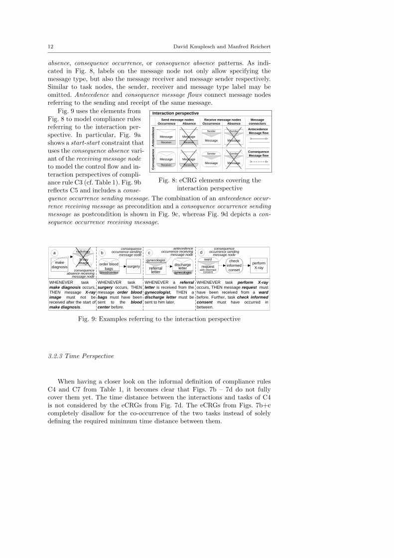
absence, consequence occurrence, or consequence absence patterns. As indi-cated in Fig. 8, labels on the message node not only allow specifying themessage type, but also the message receiver and message sender respectively.Similar to task nodes, the sender, receiver and message type label may beomitted. Antecedence and consequence message flows connect message nodesreferring to the sending and receipt of the same message.
Fig. 9 uses the elements from
Occurrence Absence Occurrence Absence
Sender
ReceiverMessage
Message
Sender
Message
Sender
ReceiverMessage
Message
Sender
Message
Receiver
Message
Receive message nodesSend message nodes
An
tec
ed
en
ce
Co
ns
eq
ue
nc
e
Interaction perspective
Receiver
Message
Antecedence
Consequence
connectors
Message
Message flow
Message flow
Fig. 8: eCRG elements covering theinteraction perspective
Fig. 8 to model compliance rulesreferring to the interaction per-spective. In particular, Fig. 9ashows a start-start constraint thatuses the consequence absence vari-ant of the receiving message nodeto model the control flow and in-teraction perspectives of compli-ance rule C3 (cf. Table 1). Fig. 9breflects C5 and includes a conse-quence occurrence sending message. The combination of an antecedence occur-rence receiving message as precondition and a consequence occurrence sendingmessage as postcondition is shown in Fig. 9c, whereas Fig. 9d depicts a con-sequence occurrence receiving message.
a b c d
WHENEVER task-----
make diagnosis occurs,
THEN message X-ray
image must not be
received after the start of
make diagnosis.
WHENEVER task-----
surgery occurs, THEN
message order blood
bags must have been
sent to the blood
center before.
WHENEVER task perform X-ray
occurs, THEN message request must
have been received from a ward
before. Further, task check informed
consent must have occurred in
between.
WHENEVER a referral
letter is received from the
gynecologist, THEN a
discharge letter must be
sent to him later.
radiology
X-rayimage
check
informed
conset
perform
X-ray
ward
gynecologist
referralletter
surgery
blood center
order blood
bags
gynecologist
discharge letter request
with informed consent
antecedence occurrence receiving
message node
consequence occurrence sending
message node
consequence absence receiving
message node
make
diagnosis
consequence occurrence sending
message node
Fig. 9: Examples referring to the interaction perspective
3.2.3 Time Perspective
When having a closer look on the informal definition of compliance rulesC4 and C7 from Table 1, it becomes clear that Figs. 7b – 7d do not fullycover them yet. The time distance between the interactions and tasks of C4is not considered by the eCRGs from Fig. 7d. The eCRGs from Figs. 7b+ccompletely disallow for the co-occurrence of the two tasks instead of solelydefining the required minimum time distance between them.
A Visual Language for Modeling Business Process Compliance Rules 13
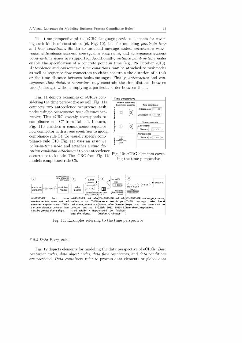
The time perspective of the eCRG language provides elements for cover-ing such kinds of constraints (cf. Fig. 10), i.e., for modeling points in timeand time conditions. Similar to task and message nodes, antecedence occur-rence, antecedence absence, consequence occurrence, and consequence absencepoint-in-time nodes are supported. Additionally, instance point-in-time nodesenable the specification of a concrete point in time (e.g., 26 October 2013).Antecedence and consequence time conditions may be attached to task nodesas well as sequence flow connectors to either constrain the duration of a taskor the time distance between tasks/messages. Finally, antecedence and con-sequence time distance connectors may constrain the time distance betweentasks/messages without implying a particular order between them.
Fig. 11 depicts examples of eCRGs con-
October 26th
2013
Occurrence Absence
Point in time nodes
An
tec
ed
en
ce
Co
ns
eq
ue
nc
eIn
sta
nc
e
Time conditions
>2d
>2d
Antecedence
Consequence
Time Connectors
Distance
Antecedence
Distance
Consequence
>2d
>2d
Time perspective
Fig. 10: eCRG elements cover-ing the time perspective
sidering the time perspective as well. Fig. 11aconnects two antecedence occurrence tasknodes using a consequence time distance con-nector. This eCRG exactly corresponds tocompliance rule C7 from Table 1. In turn,Fig. 11b enriches a consequence sequenceflow connector with a time condition to modelcompliance rule C4. To visually specify com-pliance rule C10, Fig. 11c uses an instancepoint-in-time node and attaches a time du-ration condition attachment to an antecedenceoccurrence task node. The eCRG from Fig. 11dmodels compliance rule C5.
a b c d
administer
Aspirin
WHENEVER both tasks
administer Marcumar and ad-
minister Aspirin occur, THEN
the time distance between them
must be greater than 5 days.
WHENEVER task refer
patient occurs, THEN
task admit patient must
co-occur and be fin-
ished within 7 days
after the referral.
WHENEVER task surgery occurs,
THEN message order blood
bags must have been sent no
later than 1 day before.
WHENEVER task tol-
erance test is per-
formed after October
26th, 2013, THEN it
should be finished
within 30 minutes.
administer
Marcumar > 5d
tolerance
test
≤ 30minsurgery
≥ 1d
blood center
order blood
bags
Oct 26th 2013
admit
patient
≤ 7d refer
patient
consequence time distance
connector
consequence time condition
instance point-in-time
node
Fig. 11: Examples referring to the time perspective
3.2.4 Data Perspective
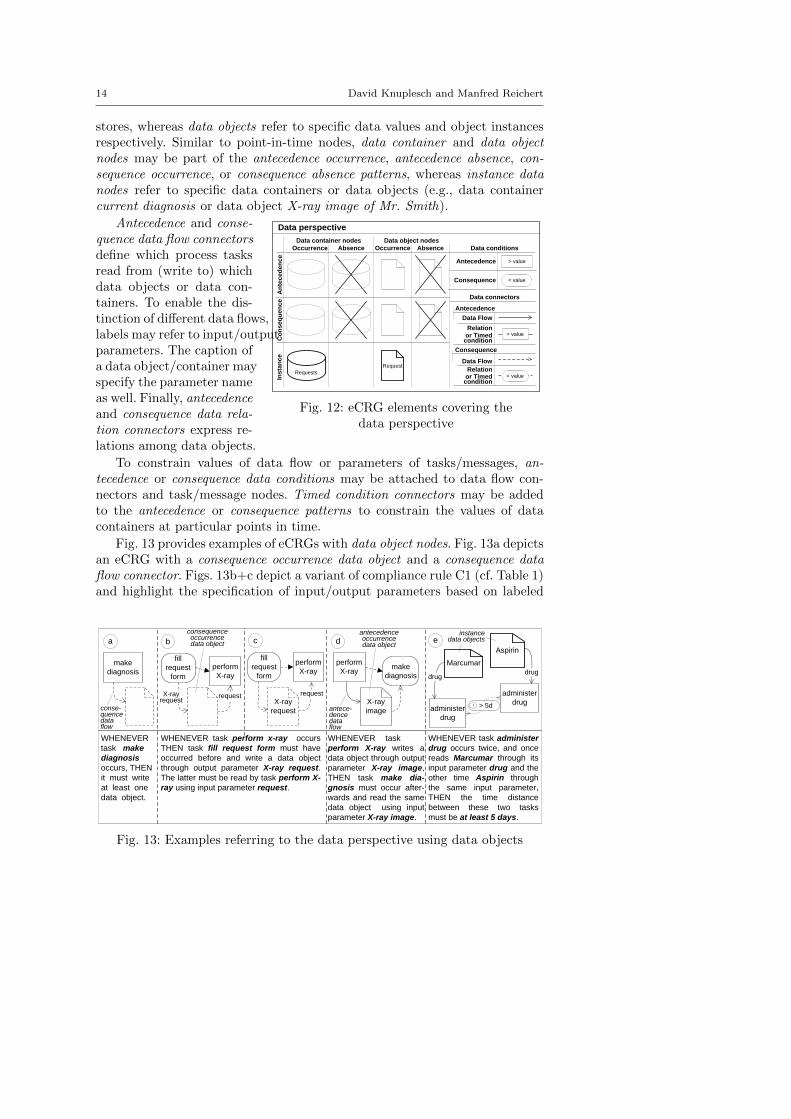
Fig. 12 depicts elements for modeling the data perspective of eCRGs: Datacontainer nodes, data object nodes, data flow connectors, and data conditionsare provided. Data containers refer to process data elements or global data
14 David Knuplesch and Manfred Reichert
stores, whereas data objects refer to specific data values and object instancesrespectively. Similar to point-in-time nodes, data container and data objectnodes may be part of the antecedence occurrence, antecedence absence, con-sequence occurrence, or consequence absence patterns, whereas instance datanodes refer to specific data containers or data objects (e.g., data containercurrent diagnosis or data object X-ray image of Mr. Smith).
Antecedence and conse-
Data object nodes
An
tec
ed
en
ce
Co
ns
eq
ue
nc
e
Requests
Request
Ins
tan
ce
Data perspective
< value
> value
Data conditions
Data connectors
Data Flow
Antecedence
Data Flow
Consequence
Occurrence Absence Occurrence Absence
Data container nodes
Antecedence
Consequence
or Timed condition
or Timed condition
> value
< valueRelation
Relation
Fig. 12: eCRG elements covering thedata perspective
quence data flow connectorsdefine which process tasksread from (write to) whichdata objects or data con-tainers. To enable the dis-tinction of different data flows,labels may refer to input/outputparameters. The caption ofa data object/container mayspecify the parameter nameas well. Finally, antecedenceand consequence data rela-tion connectors express re-lations among data objects.
To constrain values of data flow or parameters of tasks/messages, an-tecedence or consequence data conditions may be attached to data flow con-nectors and task/message nodes. Timed condition connectors may be addedto the antecedence or consequence patterns to constrain the values of datacontainers at particular points in time.
Fig. 13 provides examples of eCRGs with data object nodes. Fig. 13a depictsan eCRG with a consequence occurrence data object and a consequence dataflow connector. Figs. 13b+c depict a variant of compliance rule C1 (cf. Table 1)and highlight the specification of input/output parameters based on labeled
a
fill
request
form
b
perform
X-ray
fill
request
form
perform
X-raymake
diagnosis
perform
X-ray
c d e
make
diagnosis
WHENEVER
task make
diagnosis
occurs, THEN
it must write
at least one
data object.
WHENEVER task perform x-ray occurs
THEN task fill request form must have
occurred before and write a data object
through output parameter X-ray request.
The latter must be read by task perform X-
ray using input parameter request.
WHENEVER task -----
perform X-ray writes a
data object through output
parameter X-ray image,
THEN task make dia-
gnosis must occur after-
wards and read the same
data object using input
parameter X-ray image.
WHENEVER task administer
drug occurs twice, and once
reads Marcumar through its
input parameter drug and the
other time Aspirin through
the same input parameter,
THEN the time distance
between these two tasks
must be at least 5 days.
X-rayrequest
request request
X-ray
request
X-ray
image
administer
drugadminister
drug
> 5d
Aspirin
Marcumar
drugdrug
consequence occurrence data object
antecedenceoccurrence data object
instancedata objects
conse-quence data flow
antece-dence data flow
Fig. 13: Examples referring to the data perspective using data objects
A Visual Language for Modeling Business Process Compliance Rules 15
a b c d e
perform
X-ray
WHENEVER task-----
perform X-ray occurs,
THEN task fill request
form must occur
before and use output
parameter X-ray re-
quest to write into a
data container. Further,
perform X-ray must
read the same data
container using input
parameter request.
WHENEVER task-----
perform X-ray occurs
and reads from data
container X-ray re-
quest through its input
parameter request,
THEN the data object
read must have been
written before by task
fill request form via
output parameter X-ray
request
WHENEVER task-----
surgery occurs and
reads the platelet
count from a data
container, THEN task
analyse blood must
have occurred before
and stored a value
through its output
parameter count in
the same data
container.
WHENEVER task-----
surgery occurs and
reads from data con-
tainer platelet count
through input para-
meter count, THEN
task analyse blood
must have occurred
before and written to
data container platel-
et count via its out-
put parameter count.
request
fill
request
form
X-ray request
perform
X-ray
request
fillrequest
form
X-ray request
surgeryanalyse
blood
count
platelet count
perform
X-ray
request
fill
request
form
X-ray request
surgery
count
analyse
blood
count
platelet count
X-rayrequest
radiology
WHENEVER tasks----
perform X-ray and
task fill request form
occur and the output
parameter X-ray re-
quest of the latter task
is not written to the
same data container
from which task
perform X-ray reads
through input parame-
ter request, THEN...
consequence occurrence
data container
antecedence absence
data container
instancedata container
Fig. 14: Examples referring to the data perspective using data containers
consequence occurrence data objects and consequence data flow connectors. Anantecedence occurrence data object and the corresponding antecedence dataflow are shown in Fig. 13d, whereas Fig. 13e uses two particular instances ofdata objects (i.e., Marcumar and Aspirin) to model compliance rule C7.
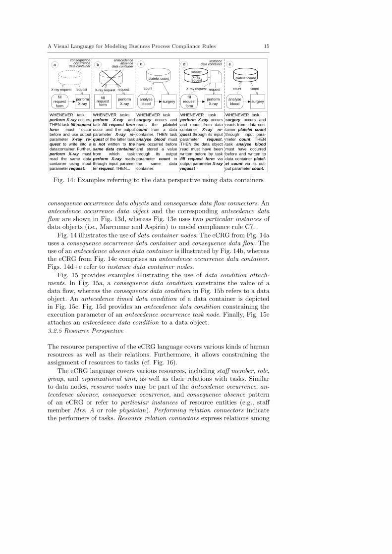
Fig. 14 illustrates the use of data container nodes. The eCRG from Fig. 14auses a consequence occurrence data container and consequence data flow. Theuse of an antecedence absence data container is illustrated by Fig. 14b, whereasthe eCRG from Fig. 14c comprises an antecedence occurrence data container.Figs. 14d+e refer to instance data container nodes.
Fig. 15 provides examples illustrating the use of data condition attach-ments. In Fig. 15a, a consequence data condition constrains the value of adata flow, whereas the consequence data condition in Fig. 15b refers to a dataobject. An antecedence timed data condition of a data container is depictedin Fig. 15c. Fig. 15d provides an antecedence data condition constraining theexecution parameter of an antecedence occurrence task node. Finally, Fig. 15eattaches an antecedence data condition to a data object.
3.2.5 Resource Perspective
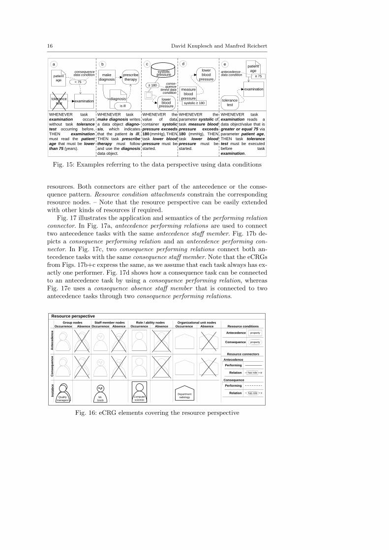
The resource perspective of the eCRG language covers various kinds of humanresources as well as their relations. Furthermore, it allows constraining theassignment of resources to tasks (cf. Fig. 16).
The eCRG language covers various resources, including staff member, role,group, and organizational unit, as well as their relations with tasks. Similarto data nodes, resource nodes may be part of the antecedence occurrence, an-tecedence absence, consequence occurrence, and consequence absence patternof an eCRG or refer to particular instances of resource entities (e.g., staffmember Mrs. A or role physician). Performing relation connectors indicatethe performers of tasks. Resource relation connectors express relations among
16 David Knuplesch and Manfred Reichert
a b c d e
WHENEVER task-----
examination occurs
without task tolerance
test occurring before,
THEN examination
must read the patient
age that must be lower
than 75 (years).
WHENEVER task-----
make diagnosis writes
a data object diagno-
sis, which indicates
that the patient is ill,
THEN task prescribe
therapy must follow
and use the diagnosis
data object.
WHENEVER the
parameter systolic of
task measure blood
pressure exceeds
180 (mmHg), THEN
task lower blood
pressure must be
started.
WHENEVER the
value of data
container systolic
pressure exceeds
180 (mmHg), THEN
task lower blood
pressure must be
started.
WHENEVER task-----
examination reads a
data object/value that is
greater or equal 75 via
parameter patient age,
THEN task tolerance
test must be executed
before task
examination.
lower blood
pressure
measure
blood
pressure
prescribe
therapy
diagnosis
is ill
≥ 180
lower
blood
pressure
systolic ≥ 180
tolerance
test
patient
age
patient
age
≥ 75
tolerance
test
examination
systolic
pressure
make
diagnosis
examination
consequencedata condition
< 75
antecedencedata condition
conse-quence
timed data condition
Fig. 15: Examples referring to the data perspective using data conditions
resources. Both connectors are either part of the antecedence or the conse-quence pattern. Resource condition attachments constrain the correspondingresource nodes. – Note that the resource perspective can be easily extendedwith other kinds of resources if required.
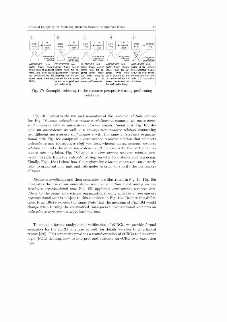
Fig. 17 illustrates the application and semantics of the performing relationconnector. In Fig. 17a, antecedence performing relations are used to connecttwo antecedence tasks with the same antecedence staff member. Fig. 17b de-picts a consequence performing relation and an antecedence performing con-nector. In Fig. 17c, two consequence performing relations connect both an-tecedence tasks with the same consequence staff member. Note that the eCRGsfrom Figs. 17b+c express the same, as we assume that each task always has ex-actly one performer. Fig. 17d shows how a consequence task can be connectedto an antecedence task by using a consequence performing relation, whereasFig. 17e uses a consequence absence staff member that is connected to twoantecedence tasks through two consequence performing relations.
Group nodes
Resource perspective
An
tec
ed
en
ce
Co
ns
eq
ue
nc
eIn
sta
bc
e
Mr.
Smith
Computer
scientistQuality
managers
Department
radiology
property
propertyAntecedence
Consequence
Resource conditions
Resource connectors
Performing
Relation
Antecedence
has role
Relation
Consequence
has role
AbsenceOccurrence Absence AbsenceOccurrence AbsenceOccurrence
Staff member nodes Role / ability nodes Organizational unit nodes
Performing
Occurrence
Fig. 16: eCRG elements covering the resource perspective
A Visual Language for Modeling Business Process Compliance Rules 17
a
order
X-ray
b
fill
request
form
order
X-ray
fill
request
form
fill
request
form
order
X-ray
perform
X-ray
order
X-ray
c d e
order
X-ray
fill
request
form
WHENEVER task-----
order X-ray occurs
before task fill request
form, and both tasks
are performed by the
same staff member,
THEN ...
WHENEVER task-----
order X-ray occurs
before task fill re-
quest form, THEN fill
request must be per-
formed by the same
actor who perform-
ed order X-ray.
WHENEVER task-----
order X-ray occurs
before task fill re-
quest form, THEN
both tasks must be
performed by the
same staff member.
WHENEVER task-----
order X-ray occurs,
THEN task fill re-
quest form must
occur afterwards and
be performed by the
same performer as
for task order X-ray.
WHENEVER task-----
order X-ray occurs
before perform X-ray,
THEN no staff mem-
ber must perform both
tasks (i.e., separation
of duties).
consequence occurrence
staff member
antecedence performing
relation
consequence absence
staff member
antecedence occurrence
staff member
consequence performing
relation
Fig. 17: Examples referring to the resource perspective using performingrelations
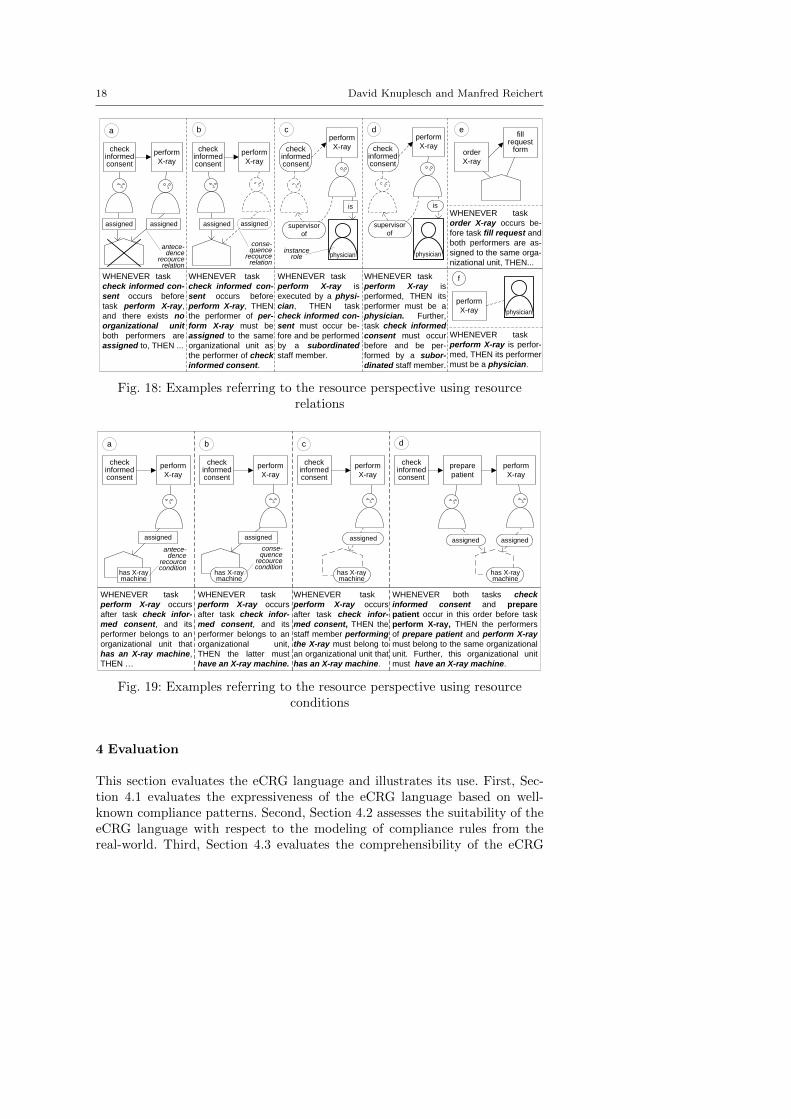
Fig. 18 illustrates the use and semantics of the resource relation connec-tor. Fig. 18a uses antecedence resource relations to connect two antecedencestaff members with an antecedence absence organizational unit. Fig. 18b de-picts an antecedence as well as a consequence resource relation connectingtwo different antecedence staff members with the same antecedence organiza-tional unit. Fig. 18c comprises a consequence resource relation that connectsantecedence and consequence staff members, whereas an antecedence resourcerelation connects the same antecedence staff member with the particular in-stance role physician. Fig. 18d applies a consequence resource relation con-nector to refer from the antecedence staff member to instance role physician.Finally, Figs. 18e+f show how the performing relation connector can directlyrefer to organizational unit and role nodes in order to specify the performersof tasks.
Resource conditions and their semantics are illustrated in Fig. 19. Fig. 19aillustrates the use of an antecedence resource condition constraining an an-tecedence organizational unit. Fig. 19b applies a consequence resource con-dition to the same antecedence organizational unit, whereas a consequenceorganizational unit is subject to this condition in Fig. 19c. Despite this differ-ence, Figs. 19b+c express the same. Note that the meaning of Fig. 19d wouldchange when turning the constrained consequence organizational unit into anantecedence consequence organizational unit.
To enable a formal analysis and verification of eCRGs, we provide formalsemantics for the eCRG language as well (for details we refer to a technicalreport [49]). This semantics provides a transformation of eCRGs to first-orderlogic (FOL) defining how to interpret and evaluate an eCRG over executionlogs.
18 David Knuplesch and Manfred Reichert
a b
check informed consent
perform
X-ray
c
check informed consent
perform
X-ray
check informed consent
perform
X-ray
supervisor
of
e
order
X-ray
fill
request form
d
is
WHENEVER task-----
check informed con-
sent occurs before
task perform X-ray,
and there exists no
organizational unit
both performers are
assigned to, THEN ...
WHENEVER task-----
check informed con-
sent occurs before
perform X-ray, THEN
the performer of per-
form X-ray must be
assigned to the same
organizational unit as
the performer of check
informed consent.
WHENEVER task-----
perform X-ray is
executed by a physi-
cian, THEN task
check informed con-
sent must occur be-
fore and be performed
by a subordinated
staff member.
WHENEVER task-----
perform X-ray is
performed, THEN its
performer must be a
physician. Further,
task check informed
consent must occur
before and be per-
formed by a subor-
dinated staff member.
WHENEVER task-----
order X-ray occurs be-
fore task fill request and
both performers are as-
signed to the same orga-
nizational unit, THEN...
assigned
assigned
assigned assigned
physician
check informed consent
perform
X-ray
supervisor
of
physician
is
perform
X-ray
f
physician
WHENEVER task-----
perform X-ray is perfor-
med, THEN its performer
must be a physician.
antece-dence
recourcerelation
conse-quence
recourcerelation
instancerole
Fig. 18: Examples referring to the resource perspective using resourcerelations
a
check informed consent
perform
X-ray
WHENEVER task-----
perform X-ray occurs
after task check infor-
med consent, and its
performer belongs to an
organizational unit that
has an X-ray machine,
THEN …
WHENEVER task-----
perform X-ray occurs
after task check infor-
med consent, and its
performer belongs to an
organizational unit,
THEN the latter must
have an X-ray machine.
WHENEVER task-----
perform X-ray occurs
after task check infor-
med consent, THEN the
staff member performing
the X-ray must belong to
an organizational unit that
has an X-ray machine.
WHENEVER both tasks check
informed consent and prepare
patient occur in this order before task
perform X-ray, THEN the performers
of prepare patient and perform X-ray
must belong to the same organizational
unit. Further, this organizational unit
must have an X-ray machine.
has X-ray machine
b
check informed consent
perform
X-ray
c
check informed consent
perform
X-ray
d
check informed consent
prepare
patient
perform
X-ray
assignedassigned
assigned
assignedassigned
antece-dence
recourcecondition
conse-quence
recourcecondition
has X-ray machine
has X-ray machine
has X-ray machine
Fig. 19: Examples referring to the resource perspective using resourceconditions
4 Evaluation
This section evaluates the eCRG language and illustrates its use. First, Sec-tion 4.1 evaluates the expressiveness of the eCRG language based on well-known compliance patterns. Second, Section 4.2 assesses the suitability of theeCRG language with respect to the modeling of compliance rules from thereal-world. Third, Section 4.3 evaluates the comprehensibility of the eCRG
A Visual Language for Modeling Business Process Compliance Rules 19
language through an empirical study. Finally, Section 4.4 presents a proof-of-concept prototype demonstrating the feasibility of an eCRG-based tool en-abling compliance modeling and automated compliance checking.
4.1 Pattern-based Evaluation
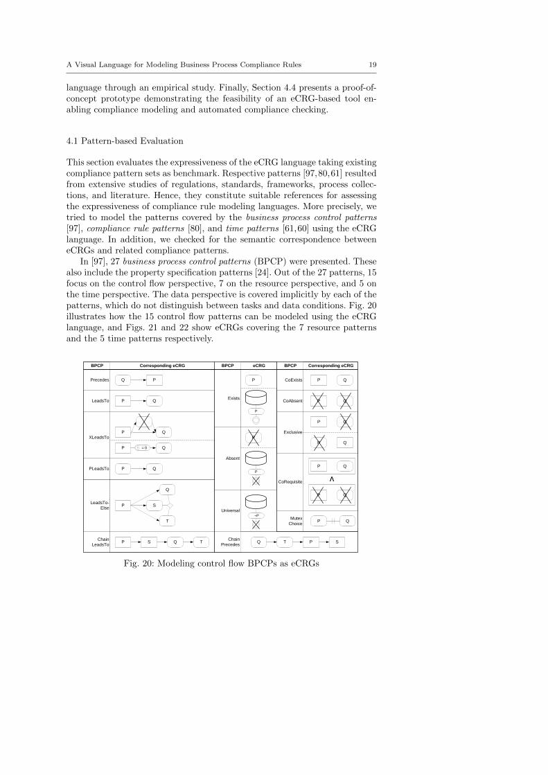
This section evaluates the expressiveness of the eCRG language taking existingcompliance pattern sets as benchmark. Respective patterns [97,80,61] resultedfrom extensive studies of regulations, standards, frameworks, process collec-tions, and literature. Hence, they constitute suitable references for assessingthe expressiveness of compliance rule modeling languages. More precisely, wetried to model the patterns covered by the business process control patterns[97], compliance rule patterns [80], and time patterns [61,60] using the eCRGlanguage. In addition, we checked for the semantic correspondence betweeneCRGs and related compliance patterns.
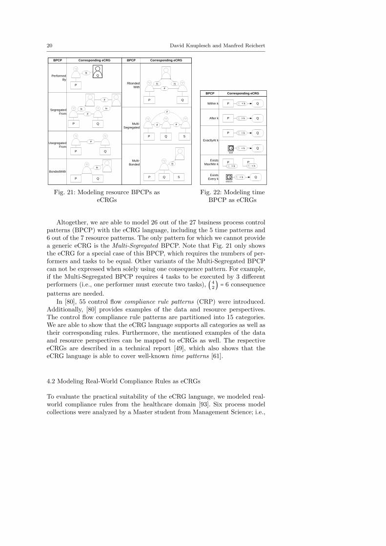
In [97], 27 business process control patterns (BPCP) were presented. Thesealso include the property specification patterns [24]. Out of the 27 patterns, 15focus on the control flow perspective, 7 on the resource perspective, and 5 onthe time perspective. The data perspective is covered implicitly by each of thepatterns, which do not distinguish between tasks and data conditions. Fig. 20illustrates how the 15 control flow patterns can be modeled using the eCRGlanguage, and Figs. 21 and 22 show eCRGs covering the 7 resource patternsand the 5 time patterns respectively.
Q P
Q P
QP
Q P
Q P = 0
Precedes
LeadsTo
XLeadsTo
PLeadsTo
Q S P T S PQ TChain
LeadsTo
Chain
Precedes
P
Exists
Absent
P
P
P
¬P
Universal
Q P
Q P
CoExists
CoAbsent
Exclusive
CoRequisite
Q P
P Q
Q P
Q P
v
QPMutex
Choice
P
Q
S
T
LeadsTo-
Else
BPCP Corresponding eCRG BPCP eCRG BPCP Corresponding eCRG
Fig. 20: Modeling control flow BPCPs as eCRGs
20 David Knuplesch and Manfred Reichert
Q
P
Performed
By
Segregated
From
is
is is
≠
≠
≠
Usegregated
From
P Q
is
BondedWith
P Q
is is
≠
Rbonded
With
P
S
≠
≠
≠
P Q
is
S
Multi-
Segregated
Multi-
Bonded
Q
P Q
P Q
BPCP Corresponding eCRG BPCP Corresponding eCRG
Fig. 21: Modeling resource BPCPs aseCRGs
Q P < kWithin k
After k Q P > k
Q P = k
Q = k
ExactlyAt k
P > k
Exists
Max/Min k P
< k
Exists
Every kQ < k
every k
start
BPCP Corresponding eCRG
Fig. 22: Modeling timeBPCP as eCRGs
Altogether, we are able to model 26 out of the 27 business process controlpatterns (BPCP) with the eCRG language, including the 5 time patterns and6 out of the 7 resource patterns. The only pattern for which we cannot providea generic eCRG is the Multi-Segregated BPCP. Note that Fig. 21 only showsthe eCRG for a special case of this BPCP, which requires the numbers of per-formers and tasks to be equal. Other variants of the Multi-Segregated BPCPcan not be expressed when solely using one consequence pattern. For example,if the Multi-Segregated BPCP requires 4 tasks to be executed by 3 differentperformers (i.e., one performer must execute two tasks), ( 4
2) = 6 consequence
patterns are needed.
In [80], 55 control flow compliance rule patterns (CRP) were introduced.Additionally, [80] provides examples of the data and resource perspectives.The control flow compliance rule patterns are partitioned into 15 categories.We are able to show that the eCRG language supports all categories as well astheir corresponding rules. Furthermore, the mentioned examples of the dataand resource perspectives can be mapped to eCRGs as well. The respectiveeCRGs are described in a technical report [49], which also shows that theeCRG language is able to cover well-known time patterns [61].
4.2 Modeling Real-World Compliance Rules as eCRGs
To evaluate the practical suitability of the eCRG language, we modeled real-world compliance rules from the healthcare domain [93]. Six process modelcollections were analyzed by a Master student from Management Science; i.e.,
A Visual Language for Modeling Business Process Compliance Rules 21
someone with competencies comparable to a business analyst rather than toan IT expert. The student checked whether the process model collections arerelated to compliance rules and, if yes, whether these can be modeled with theeCRG language. The student performed these analyzes within a period of sixmonth.
The process model collections and related artifacts had been created inthe context of a large process reengineering project at a university hospital(cf. Section 2). The collections contain process models related to laboratoryexaminations [55], radiological services [56], therapeutic treatments [92,90],and surgeries [54,91]. The corresponding process models are described bothvisually and as text, providing information about the data and resource per-spectives (e.g., organizational units, human resources) as well. Finally, theorganizational structure of the hospital is described in terms of organizationcharts [53].
Before the study, the Master student received specific training. She at-tended a course on business process management, which included a lecture onbusiness process compliance [86], and received a 30 minutes introduction intothe eCRG language. Furthermore, relevant eCRG documentations (i.e., [50,49]) and Microsoft Visio shapes representing the eCRG elements were handedover to her.
Altogether, the Master student identified 30 compliance rules in the con-text of the six process model collections. Out of these 30 compliance rules, 5refer to the interaction perspective, 8 to the time perspective, 14 to the dataperspective, and 17 to the resource perspective. Note that a particular compli-ance rule may refer to multiple perspectives as well. The Master student wasable to model each of the 30 compliance rules using the eCRG language andMicrosoft Visio as modeling tool. The correctness of the eCRGs was reviewedtwice. An IT expert, being familiar with the eCRG language, checked the syn-tax. The semantics (i.e., meaning) of the eCRGs was validated by a subjectmatter expert involved in the aforementioned process reengineering project.
Modeling real-world compliance rules revealed a few drawbacks regardingthe modeling of the control flow, interaction and time perspectives. In partic-ular, it emphasizes the missing ability to refine tasks or to constrain businesspartners sending or receiving messages. Finally, a specific symbol for explain-ing periodic time events was missing. Such a symbol might ease the distinctionbetween point-in-time nodes that refer to periodic and one-time events.
4.3 Experimental Evaluation
To evaluate the comprehensibility of the eCRG language, we conducted acontrolled experiment. The latter investigated the use of the eCRG languageby students from Management Science (i.e. prospective business analysts) andComputer Science. All subjects had been provided with a short training before.
First, we tested whether the reading of eCRGs supports subjects in under-standing the meaning of the respective rules (cf. Hypothesis H1+H2). Second,
22 David Knuplesch and Manfred Reichert
we compared the understanding of the eCRG language for the two subjectgroups (i.e. Management Scientists and Computer Scientists – cf. HypothesisH3).
H1 Trained Management Scientists are able to understand eCRGs, i.e. readingeCRGs increases their domain understanding.
H2 Trained Computer Scientists are able to understand eCRGs, i.e. readingeCRGs increases their domain understanding.
H3 There is no large difference between Management Scientists and ComputerScientists regarding the understanding of eCRGs.
As subjects 80 students from Ulm University were chosen; 59 of themwere male and 21 female. 55 subjects studied Management Science [MS] and25 Computer Science [CS]. All subjects attended a course on business processmanagement at the time the experiment took place3 and received course creditpoints for participating in the study. Furthermore, the course included a lectureon business process compliance [86], which covered the eCRG language as well.As additional material, a course book was distributed to the students.
The study is based on a questionnaire that, first of all, requests generalinformation from the subjects (e.g., age, gender, and study program of thesubject). Then, it asks for self-ratings regarding the familiarity of the respec-tive subject with the eCRG language and related notations (e.g. BPMN).The main part of the questionnaire comprises 10 eCRGs. For each eCRG, 3questions related to domain understandability (i.e. the expressed compliancerule) were asked. A correct answer scores with one point. Accordingly, themaximum total score is 30, expressing that the respective subject was ableto answer all questions correctly. Each time after answering 6 questions (i.e.,after processing two eCRGs), the subject is asked additional questions.
To rule out learning effects due to the labeling of the eCRG elements,we provided two versions of the questionnaire that alternately abstract theelements of eCRGs; i.e. concrete labels are replaced by abstract identifiers(e.g., using label Task A instead of label check job application). This ensuresthat any measured increase in understandability can be directly related to theeCRG language, i.e., it is not biased due to existing domain knowledge of thesubjects. Finally, we recorded the time needed by the respective subjects toprocess the questionnaire.
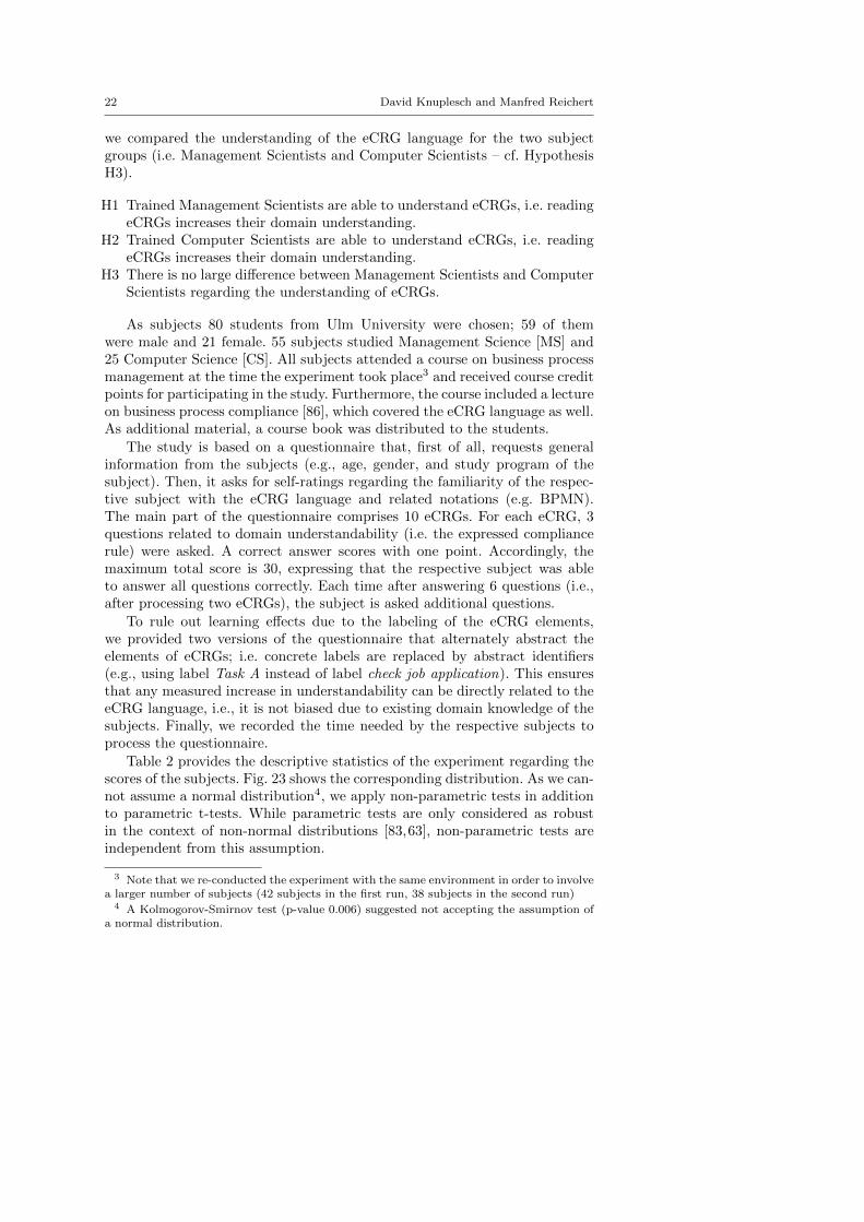
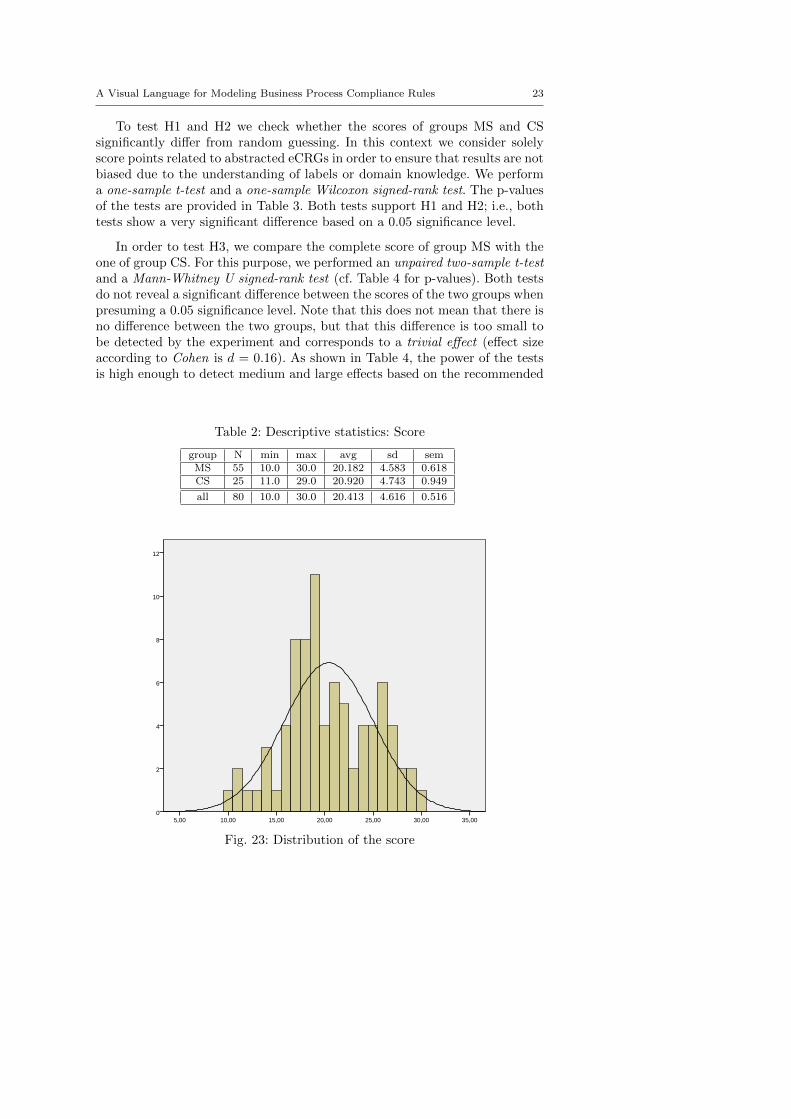
Table 2 provides the descriptive statistics of the experiment regarding thescores of the subjects. Fig. 23 shows the corresponding distribution. As we can-not assume a normal distribution4, we apply non-parametric tests in additionto parametric t-tests. While parametric tests are only considered as robustin the context of non-normal distributions [83,63], non-parametric tests areindependent from this assumption.
3 Note that we re-conducted the experiment with the same environment in order to involvea larger number of subjects (42 subjects in the first run, 38 subjects in the second run)
4 A Kolmogorov-Smirnov test (p-value 0.006) suggested not accepting the assumption ofa normal distribution.
A Visual Language for Modeling Business Process Compliance Rules 23
To test H1 and H2 we check whether the scores of groups MS and CSsignificantly differ from random guessing. In this context we consider solelyscore points related to abstracted eCRGs in order to ensure that results are notbiased due to the understanding of labels or domain knowledge. We performa one-sample t-test and a one-sample Wilcoxon signed-rank test. The p-valuesof the tests are provided in Table 3. Both tests support H1 and H2; i.e., bothtests show a very significant difference based on a 0.05 significance level.
In order to test H3, we compare the complete score of group MS with theone of group CS. For this purpose, we performed an unpaired two-sample t-testand a Mann-Whitney U signed-rank test (cf. Table 4 for p-values). Both testsdo not reveal a significant difference between the scores of the two groups whenpresuming a 0.05 significance level. Note that this does not mean that there isno difference between the two groups, but that this difference is too small tobe detected by the experiment and corresponds to a trivial effect (effect sizeaccording to Cohen is d = 0.16). As shown in Table 4, the power of the testsis high enough to detect medium and large effects based on the recommended
Table 2: Descriptive statistics: Score
group N min max avg sd semMS 55 10.0 30.0 20.182 4.583 0.618CS 25 11.0 29.0 20.920 4.743 0.949
all 80 10.0 30.0 20.413 4.616 0.516
12
10
8
6
4
2
035,0030,0025,0020,0015,0010,005,00
Seite 1
Fig. 23: Distribution of the score
24 David Knuplesch and Manfred Reichert
Table 3: Increase in domain understanding (H1 and H2)
one-sample t-test one-sample Wilcoxon signed-rankH1 <0.001 <0.001H2 <0.001 <0.001
Table 4: Comparing group MS with group CS (H3)
unpaired two-sample t-test Mann-Whitney UH3 0.511 0.670
Power (d = 0.7 ∥ ≥ ± 3.27) 0.819 0.801Power (d = 0.8 ∥ ≥ ± 3.73) 0.906 0.892
0.80 level. Such an effect corresponds to a difference of at least 3.27 points inthe context of our experiment [28,21].5
Altogether, the experiment confirms that Management Scientists (i.e. noIT experts) are able to understand eCRGs and their eCRG understanding canreach a level not largely differing from the one of Computer Scientists (i.e., ITexperts).
Limitations. Apparently, the experiment faces several limitations. First, wedid not involve and compare professional business analysts and IT expertsfrom industry, but prospective ones (i.e. students). Although various investi-gations have shown that students are proper substitutes for professionals inempirical studies (e.g. [42,96]) the results for professionals may differ. Second,the experiment uses 10 prespecified eCRGs that address all process perspec-tives supported by the eCRG language as well as its core elements. However,the questionnaire neither included all elements of the eCRG language nor didit consider all possible combinations of language elements. Accordingly, wecannot ensure that we always obtain similar results for the various eCRGs.Finally, the sample size of the experiments only allows detecting medium andlarge differences.
4.4 Proof-of-Concept Prototype
To demonstrate the feasibility of a-posteriori compliance checking [47] basedon the eCRG language, we implemented a proof-of-concept prototype.
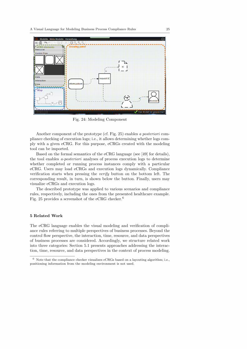
The modeling component of this prototype is depicted in Fig. 24. On theleft, the elements of the eCRG language (i.e., nodes, edges and attachments)are displayed, which may then be dragged and dropped on the drawing panelin the center. The latter allows layouting the elements and connecting themwith each other. The map on the bottom left highlights the active region ofthe drawing panel. Furthermore, the modeling environment supports differentexport formats including svg, jpg, pdf, and xml.
5 Interpretation of Cohen’s d: d ≥ 0.8 large effect, 0.8 > d ≥ 0.5 medium effect, 0.5 > d ≥ 0.2small effect, d < 0.2 trivial/no effect
A Visual Language for Modeling Business Process Compliance Rules 25
Fig. 24: Modeling Component
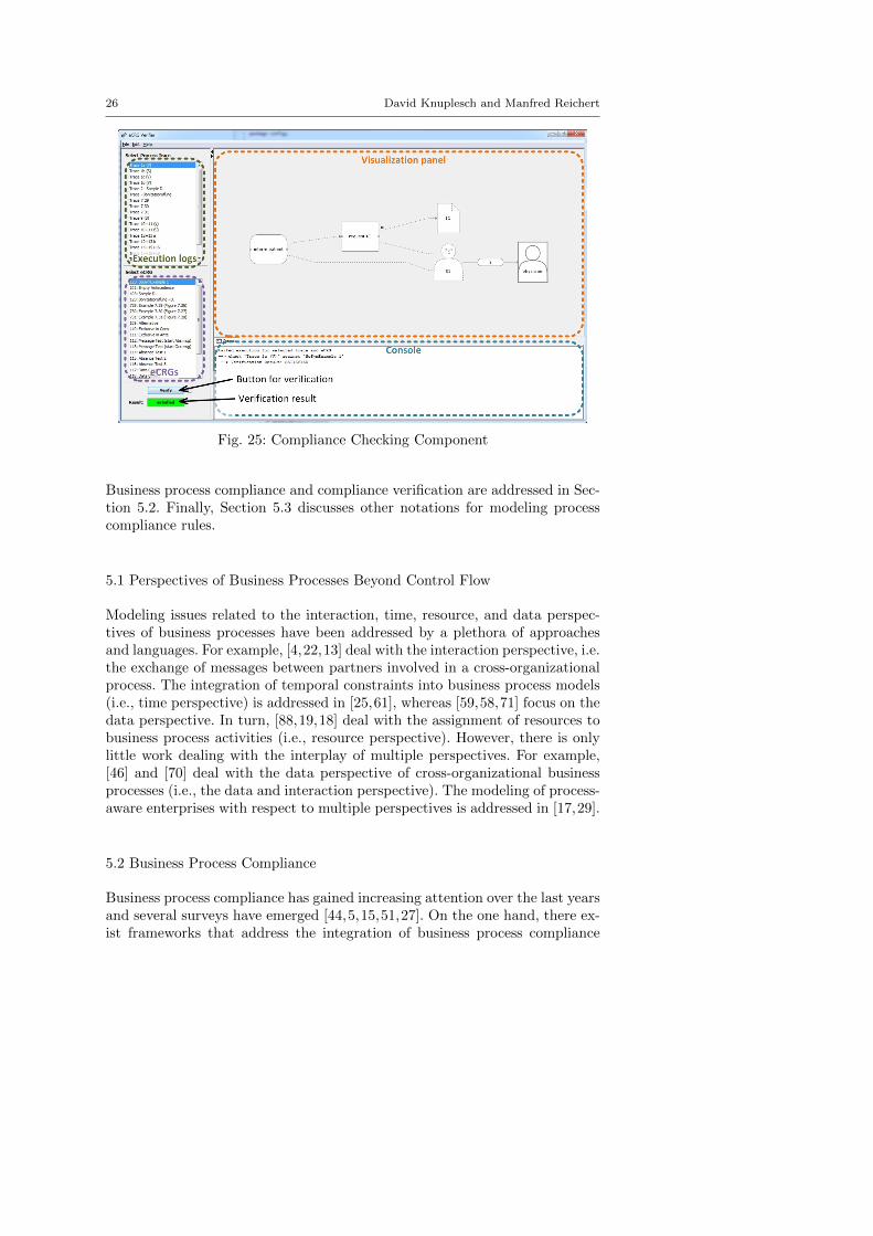
Another component of the prototype (cf. Fig. 25) enables a posteriori com-pliance checking of execution logs; i.e., it allows determining whether logs com-ply with a given eCRG. For this purpose, eCRGs created with the modelingtool can be imported.
Based on the formal semantics of the eCRG language (see [49] for details),the tool enables a-posteriori analyses of process execution logs to determinewhether completed or running process instances comply with a particulareCRG. Users may load eCRGs and execution logs dynamically. Complianceverification starts when pressing the verify button on the bottom left. Thecorresponding result, in turn, is shown below the button. Finally, users mayvisualize eCRGs and execution logs.
The described prototype was applied to various scenarios and compliancerules, respectively, including the ones from the presented healthcare example.Fig. 25 provides a screenshot of the eCRG checker.6
5 Related Work
The eCRG language enables the visual modeling and verification of compli-ance rules referring to multiple perspectives of business processes. Beyond thecontrol flow perspective, the interaction, time, resource, and data perspectivesof business processes are considered. Accordingly, we structure related workinto three categories: Section 5.1 presents approaches addressing the interac-tion, time, resource, and data perspectives in the context of process modeling.
6 Note that the compliance checker visualizes eCRGs based on a layouting algorithm; i.e.,positioning information from the modeling environment is not used.
26 David Knuplesch and Manfred Reichert
Fig. 25: Compliance Checking Component
Business process compliance and compliance verification are addressed in Sec-tion 5.2. Finally, Section 5.3 discusses other notations for modeling processcompliance rules.
5.1 Perspectives of Business Processes Beyond Control Flow
Modeling issues related to the interaction, time, resource, and data perspec-tives of business processes have been addressed by a plethora of approachesand languages. For example, [4,22,13] deal with the interaction perspective, i.e.the exchange of messages between partners involved in a cross-organizationalprocess. The integration of temporal constraints into business process models(i.e., time perspective) is addressed in [25,61], whereas [59,58,71] focus on thedata perspective. In turn, [88,19,18] deal with the assignment of resources tobusiness process activities (i.e., resource perspective). However, there is onlylittle work dealing with the interplay of multiple perspectives. For example,[46] and [70] deal with the data perspective of cross-organizational businessprocesses (i.e., the data and interaction perspective). The modeling of process-aware enterprises with respect to multiple perspectives is addressed in [17,29].
5.2 Business Process Compliance
Business process compliance has gained increasing attention over the last yearsand several surveys have emerged [44,5,15,51,27]. On the one hand, there ex-ist frameworks that address the integration of business process compliance
A Visual Language for Modeling Business Process Compliance Rules 27
throughout the entire process lifecycle [47,65,81]. On the other, there are ap-proaches dealing with business process compliance in a particular stage ofthe process lifecyle. In particular, [2,80,78] provide techniques for a-posterioriverifying the compliance of execution logs with a set of constraints. Certainapproaches not only focus on the control flow perspective, but take the timeperspective [82] or resource perspective [14] into account as well. To be ableto quickly react to compliance violations or to prevent them, compliance mon-itoring [16,31,67–69] and continous auditing [8] allow detecting process com-pliance violations during runtime. A framework for comparing respective ap-proaches is proposed by [64]. To verify whether compliance rules are met by aparticular process model at design time, a multitude of approaches exist apply-ing model checking techniques (e.g., [30,62]). In this context, [10,45] considerthe data perspective and [48,52] the interaction perspective. An approachchecking the compliance of process models with respect to given semanticconstraints and ensuring the validity of process change operations based onMixed-Integer Programming formulation is proposed in [57]. The latter fur-ther introduces notions like degree of compliance, validity of change operations,and compliance by compensation. Other approaches for verifying complianceat design time apply the notion of semantic congruence [41] or use Petri Nets[6], considering the data and time perspectives as well. Finally, declarativeapproaches [32,79,7,37,99] ensure compliance in an elegant way. Since pro-cesses are defined by means of a set of constraints, imposed compliance rulesonly have to be added to the process definition to ensure business processcompliance.
5.3 Compliance Rule Notations
To enable the verification of business process compliance rules, the latter mustbe specified unambiguously in a machine-readable way. For this purpose, [35]developed a logic-based formalism for describing both the semantics of nor-mative specifications and compliance checking procedures. This approach al-lows modeling business obligations and regulating the execution of businessprocesses. In turn, [24,74,97,80] apply patterns to specify compliance rules.Furthermore, there are approaches using semantic annotations to ensure com-pliance [33]. Other approaches rely on temporal logics (e.g., [30,45,26]), likethe linear temporal logic (LTL), with which the control flow perspective canbe modeled based on operators like next, eventually, always, and until.
An approach for visually modeling compliance is described in [10,11]. Itconsiders the control flow and data perspectives; [89] additionally includessecurity constraints. There exist other visual approaches for compliance rulemodeling [62,66,26], which focus on the control flow and partially on the dataperspective, but ignore the other perspectives.
A generic querying language, which can be applied to a wide range ofconceptual models is presented in [23]. In particular, this language can beused to specify compliance rules as well.
28 David Knuplesch and Manfred Reichert
An approach connecting visual compliance rule notations with informaland textual specifications is presented in [95], whereas [98] deals with thetransformation of natural text into formal compliance rules.
Visual notations for declarative business processes (e.g., DECLARE [79],DCR Graphs [40]) could be used to model compliance rules as well. Note thatsome of these approaches address the data and/or time perspectives [72,12].
Artifact-centric approaches [43] and business rules [39] emerged recently.Furthermore, there exist commercial as well as open source business rule en-gines (e.g., IBM ILOG and JBoss Drools) and related standards (e.g., BRML[36], SBVR [76]). Note that respective approaches are expressive and allow ad-dressing the different perspectives of business processes and compliance rules.As a drawback, however, these approaches are mainly text-based, i.e., theydo not provide a visual notation with an explicit support of the control flow,interaction, time, data, and resource perspectives.
6 Summary and Outlook
While compliance rule modeling has been addressed by a plethora of ap-proaches, the integrated visual modeling of the control flow, interaction, time,data, and resource perspectives has not been sufficiently addressed yet [20,80,97]. To remedy this drawback, this paper proposes the extended ComplianceRule Graph (eCRG) language. This language not only considers the controlflow perspective, but enables the visual modeling of compliance rules with thesupport of the other mentioned perspectives as well.
Taking our previous work on the eCRG language [50,94] into account, weintroduced the elements of the eCRG language in detail and illustrated themalong examples. We showed that the eCRG language covers the various per-spectives one faces when modeling compliance rules from real-world scenarios.The provided pattern-based evaluation further confirmed the expressivenessof the eCRG language. To enable tool support for both the modeling andthe verification of compliance rules, a formal semantics of the presented vi-sual compliance rule language has been provided in a technical report [49].Based on this semantics, we implemented a proof-of-concept prototype thata-posteriori analyzes whether execution logs comply with given eCRGs, tak-ing the control flow, interaction, time, data, and resource perspectives intoaccount. To support the visual modeling of eCRGs another component of thisproof-of-concept prototype is provided by the modeling environment for theeCRG language.
In future work, we will consider the feedback we gathered during the mod-eling of real-world compliance rules to enhance the visual compliance rulelanguage. Furthermore, we will compare the eCRG language with pattern-and logic-based approaches in another empirical study. Our overall aim is toensure multi-perspective compliance for all phases of the process life cycle, in-cluding runtime compliance monitoring as well as a priori compliance checking
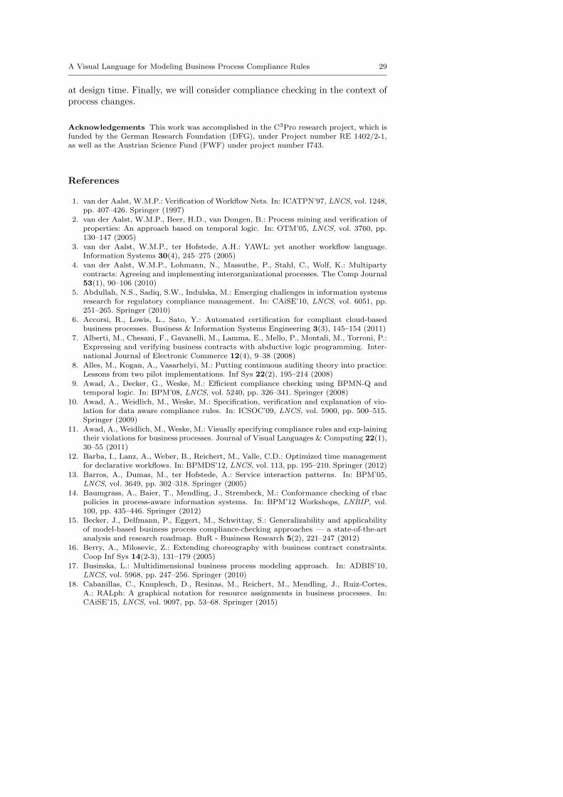
A Visual Language for Modeling Business Process Compliance Rules 29
at design time. Finally, we will consider compliance checking in the context ofprocess changes.
Acknowledgements This work was accomplished in the C3Pro research project, which isfunded by the German Research Foundation (DFG), under Project number RE 1402/2-1,as well as the Austrian Science Fund (FWF) under project number I743.
References
1. van der Aalst, W.M.P.: Verification of Workflow Nets. In: ICATPN’97, LNCS, vol. 1248,pp. 407–426. Springer (1997)
2. van der Aalst, W.M.P., Beer, H.D., van Dongen, B.: Process mining and verification ofproperties: An approach based on temporal logic. In: OTM’05, LNCS, vol. 3760, pp.130–147 (2005)
3. van der Aalst, W.M.P., ter Hofstede, A.H.: YAWL: yet another workflow language.Information Systems 30(4), 245–275 (2005)
4. van der Aalst, W.M.P., Lohmann, N., Massuthe, P., Stahl, C., Wolf, K.: Multipartycontracts: Agreeing and implementing interorganizational processes. The Comp Journal53(1), 90–106 (2010)
5. Abdullah, N.S., Sadiq, S.W., Indulska, M.: Emerging challenges in information systemsresearch for regulatory compliance management. In: CAiSE’10, LNCS, vol. 6051, pp.251–265. Springer (2010)
6. Accorsi, R., Lowis, L., Sato, Y.: Automated certification for compliant cloud-basedbusiness processes. Business & Information Systems Engineering 3(3), 145–154 (2011)
7. Alberti, M., Chesani, F., Gavanelli, M., Lamma, E., Mello, P., Montali, M., Torroni, P.:Expressing and verifying business contracts with abductive logic programming. Inter-national Journal of Electronic Commerce 12(4), 9–38 (2008)
8. Alles, M., Kogan, A., Vasarhelyi, M.: Putting continuous auditing theory into practice:Lessons from two pilot implementations. Inf Sys 22(2), 195–214 (2008)
9. Awad, A., Decker, G., Weske, M.: Efficient compliance checking using BPMN-Q andtemporal logic. In: BPM’08, LNCS, vol. 5240, pp. 326–341. Springer (2008)
10. Awad, A., Weidlich, M., Weske, M.: Specification, verification and explanation of vio-lation for data aware compliance rules. In: ICSOC’09, LNCS, vol. 5900, pp. 500–515.Springer (2009)
11. Awad, A., Weidlich, M., Weske, M.: Visually specifying compliance rules and exp-lainingtheir violations for business processes. Journal of Visual Languages & Computing 22(1),30–55 (2011)
12. Barba, I., Lanz, A., Weber, B., Reichert, M., Valle, C.D.: Optimized time managementfor declarative workflows. In: BPMDS’12, LNCS, vol. 113, pp. 195–210. Springer (2012)
13. Barros, A., Dumas, M., ter Hofstede, A.: Service interaction patterns. In: BPM’05,LNCS, vol. 3649, pp. 302–318. Springer (2005)
14. Baumgrass, A., Baier, T., Mendling, J., Strembeck, M.: Conformance checking of rbacpolicies in process-aware information systems. In: BPM’12 Workshops, LNBIP, vol.100, pp. 435–446. Springer (2012)
15. Becker, J., Delfmann, P., Eggert, M., Schwittay, S.: Generalizability and applicabilityof model-based business process compliance-checking approaches — a state-of-the-artanalysis and research roadmap. BuR - Business Research 5(2), 221–247 (2012)
16. Berry, A., Milosevic, Z.: Extending choreography with business contract constraints.Coop Inf Sys 14(2-3), 131–179 (2005)
17. Businska, L.: Multidimensional business process modeling approach. In: ADBIS’10,LNCS, vol. 5968, pp. 247–256. Springer (2010)
18. Cabanillas, C., Knuplesch, D., Resinas, M., Reichert, M., Mendling, J., Ruiz-Cortes,A.: RALph: A graphical notation for resource assignments in business processes. In:CAiSE’15, LNCS, vol. 9097, pp. 53–68. Springer (2015)
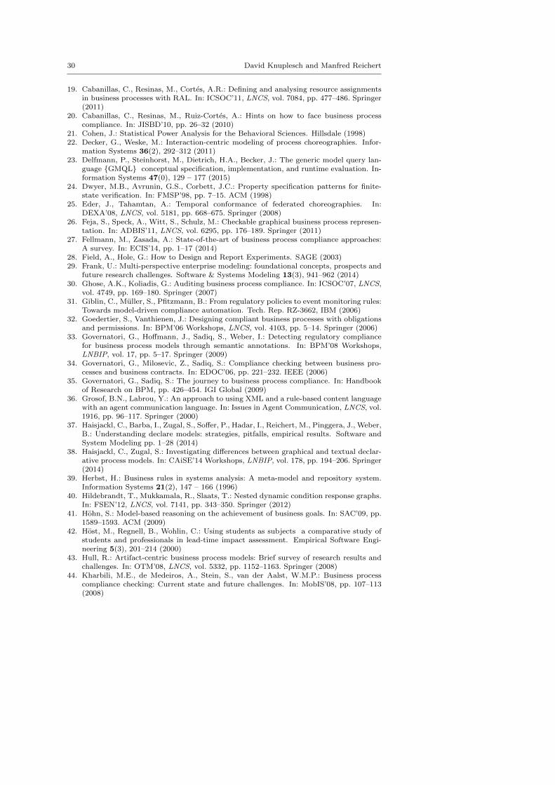
30 David Knuplesch and Manfred Reichert
19. Cabanillas, C., Resinas, M., Cortes, A.R.: Defining and analysing resource assignmentsin business processes with RAL. In: ICSOC’11, LNCS, vol. 7084, pp. 477–486. Springer(2011)
20. Cabanillas, C., Resinas, M., Ruiz-Cortes, A.: Hints on how to face business processcompliance. In: JISBD’10, pp. 26–32 (2010)
21. Cohen, J.: Statistical Power Analysis for the Behavioral Sciences. Hillsdale (1998)22. Decker, G., Weske, M.: Interaction-centric modeling of process choreographies. Infor-
mation Systems 36(2), 292–312 (2011)23. Delfmann, P., Steinhorst, M., Dietrich, H.A., Becker, J.: The generic model query lan-
guage {GMQL} conceptual specification, implementation, and runtime evaluation. In-formation Systems 47(0), 129 – 177 (2015)
24. Dwyer, M.B., Avrunin, G.S., Corbett, J.C.: Property specification patterns for finite-state verification. In: FMSP’98, pp. 7–15. ACM (1998)
25. Eder, J., Tahamtan, A.: Temporal conformance of federated choreographies. In:DEXA’08, LNCS, vol. 5181, pp. 668–675. Springer (2008)
26. Feja, S., Speck, A., Witt, S., Schulz, M.: Checkable graphical business process represen-tation. In: ADBIS’11, LNCS, vol. 6295, pp. 176–189. Springer (2011)
27. Fellmann, M., Zasada, A.: State-of-the-art of business process compliance approaches:A survey. In: ECIS’14, pp. 1–17 (2014)
28. Field, A., Hole, G.: How to Design and Report Experiments. SAGE (2003)29. Frank, U.: Multi-perspective enterprise modeling: foundational concepts, prospects and
future research challenges. Software & Systems Modeling 13(3), 941–962 (2014)30. Ghose, A.K., Koliadis, G.: Auditing business process compliance. In: ICSOC’07, LNCS,
vol. 4749, pp. 169–180. Springer (2007)31. Giblin, C., Muller, S., Pfitzmann, B.: From regulatory policies to event monitoring rules:
Towards model-driven compliance automation. Tech. Rep. RZ-3662, IBM (2006)32. Goedertier, S., Vanthienen, J.: Designing compliant business processes with obligations
and permissions. In: BPM’06 Workshops, LNCS, vol. 4103, pp. 5–14. Springer (2006)33. Governatori, G., Hoffmann, J., Sadiq, S., Weber, I.: Detecting regulatory compliance
for business process models through semantic annotations. In: BPM’08 Workshops,LNBIP, vol. 17, pp. 5–17. Springer (2009)
34. Governatori, G., Milosevic, Z., Sadiq, S.: Compliance checking between business pro-cesses and business contracts. In: EDOC’06, pp. 221–232. IEEE (2006)
35. Governatori, G., Sadiq, S.: The journey to business process compliance. In: Handbookof Research on BPM, pp. 426–454. IGI Global (2009)
36. Grosof, B.N., Labrou, Y.: An approach to using XML and a rule-based content languagewith an agent communication language. In: Issues in Agent Communication, LNCS, vol.1916, pp. 96–117. Springer (2000)
37. Haisjackl, C., Barba, I., Zugal, S., Soffer, P., Hadar, I., Reichert, M., Pinggera, J., Weber,B.: Understanding declare models: strategies, pitfalls, empirical results. Software andSystem Modeling pp. 1–28 (2014)
38. Haisjackl, C., Zugal, S.: Investigating differences between graphical and textual declar-ative process models. In: CAiSE’14 Workshops, LNBIP, vol. 178, pp. 194–206. Springer(2014)
39. Herbst, H.: Business rules in systems analysis: A meta-model and repository system.Information Systems 21(2), 147 – 166 (1996)
40. Hildebrandt, T., Mukkamala, R., Slaats, T.: Nested dynamic condition response graphs.In: FSEN’12, LNCS, vol. 7141, pp. 343–350. Springer (2012)
41. Hohn, S.: Model-based reasoning on the achievement of business goals. In: SAC’09, pp.1589–1593. ACM (2009)
42. Host, M., Regnell, B., Wohlin, C.: Using students as subjects a comparative study ofstudents and professionals in lead-time impact assessment. Empirical Software Engi-neering 5(3), 201–214 (2000)
43. Hull, R.: Artifact-centric business process models: Brief survey of research results andchallenges. In: OTM’08, LNCS, vol. 5332, pp. 1152–1163. Springer (2008)
44. Kharbili, M.E., de Medeiros, A., Stein, S., van der Aalst, W.M.P.: Business processcompliance checking: Current state and future challenges. In: MobIS’08, pp. 107–113(2008)
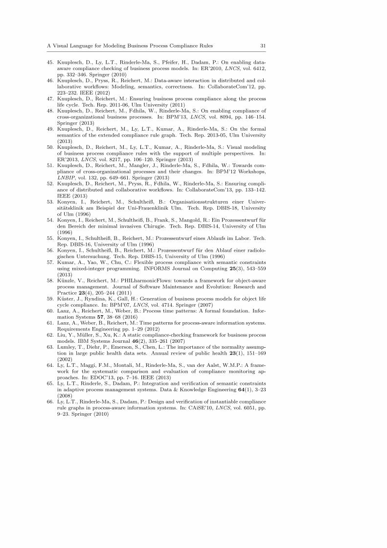
A Visual Language for Modeling Business Process Compliance Rules 31
45. Knuplesch, D., Ly, L.T., Rinderle-Ma, S., Pfeifer, H., Dadam, P.: On enabling data-aware compliance checking of business process models. In: ER’2010, LNCS, vol. 6412,pp. 332–346. Springer (2010)
46. Knuplesch, D., Pryss, R., Reichert, M.: Data-aware interaction in distributed and col-laborative workflows: Modeling, semantics, correctness. In: CollaborateCom’12, pp.223–232. IEEE (2012)
47. Knuplesch, D., Reichert, M.: Ensuring business process compliance along the processlife cycle. Tech. Rep. 2011-06, Ulm University (2011)
48. Knuplesch, D., Reichert, M., Fdhila, W., Rinderle-Ma, S.: On enabling compliance ofcross-organizational business processes. In: BPM’13, LNCS, vol. 8094, pp. 146–154.Springer (2013)
49. Knuplesch, D., Reichert, M., Ly, L.T., Kumar, A., Rinderle-Ma, S.: On the formalsemantics of the extended compliance rule graph. Tech. Rep. 2013-05, Ulm University(2013)
50. Knuplesch, D., Reichert, M., Ly, L.T., Kumar, A., Rinderle-Ma, S.: Visual modelingof business process compliance rules with the support of multiple perspectives. In:ER’2013, LNCS, vol. 8217, pp. 106–120. Springer (2013)
51. Knuplesch, D., Reichert, M., Mangler, J., Rinderle-Ma, S., Fdhila, W.: Towards com-pliance of cross-organizational processes and their changes. In: BPM’12 Workshops,LNBIP, vol. 132, pp. 649–661. Springer (2013)
52. Knuplesch, D., Reichert, M., Pryss, R., Fdhila, W., Rinderle-Ma, S.: Ensuring compli-ance of distributed and collaborative workflows. In: CollaborateCom’13, pp. 133–142.IEEE (2013)
53. Konyen, I., Reichert, M., Schultheiß, B.: Organisationsstrukturen einer Univer-sitatsklinik am Beispiel der Uni-Frauenklinik Ulm. Tech. Rep. DBIS-18, Universityof Ulm (1996)
54. Konyen, I., Reichert, M., Schultheiß, B., Frank, S., Mangold, R.: Ein Prozessentwurf furden Bereich der minimal invasiven Chirugie. Tech. Rep. DBIS-14, University of Ulm(1996)
55. Konyen, I., Schultheiß, B., Reichert, M.: Prozessentwurf eines Ablaufs im Labor. Tech.Rep. DBIS-16, University of Ulm (1996)
56. Konyen, I., Schultheiß, B., Reichert, M.: Prozessentwurf fur den Ablauf einer radiolo-gischen Untersuchung. Tech. Rep. DBIS-15, University of Ulm (1996)
57. Kumar, A., Yao, W., Chu, C.: Flexible process compliance with semantic constraintsusing mixed-integer programming. INFORMS Journal on Computing 25(3), 543–559(2013)
58. Kunzle, V., Reichert, M.: PHILharmonicFlows: towards a framework for object-awareprocess management. Journal of Software Maintenance and Evolution: Research andPractice 23(4), 205–244 (2011)
59. Kuster, J., Ryndina, K., Gall, H.: Generation of business process models for object lifecycle compliance. In: BPM’07, LNCS, vol. 4714. Springer (2007)
60. Lanz, A., Reichert, M., Weber, B.: Process time patterns: A formal foundation. Infor-mation Systems 57, 38–68 (2016)
61. Lanz, A., Weber, B., Reichert, M.: Time patterns for process-aware information systems.Requirements Engineering pp. 1–29 (2012)
62. Liu, Y., Muller, S., Xu, K.: A static compliance-checking framework for business processmodels. IBM Systems Journal 46(2), 335–261 (2007)
63. Lumley, T., Diehr, P., Emerson, S., Chen, L.: The importance of the normality assump-tion in large public health data sets. Annual review of public health 23(1), 151–169(2002)
64. Ly, L.T., Maggi, F.M., Montali, M., Rinderle-Ma, S., van der Aalst, W.M.P.: A frame-work for the systematic comparison and evaluation of compliance monitoring ap-proaches. In: EDOC’13, pp. 7–16. IEEE (2013)
65. Ly, L.T., Rinderle, S., Dadam, P.: Integration and verification of semantic constraintsin adaptive process management systems. Data & Knowledge Engineering 64(1), 3–23(2008)
66. Ly, L.T., Rinderle-Ma, S., Dadam, P.: Design and verification of instantiable compliancerule graphs in process-aware information systems. In: CAiSE’10, LNCS, vol. 6051, pp.9–23. Springer (2010)
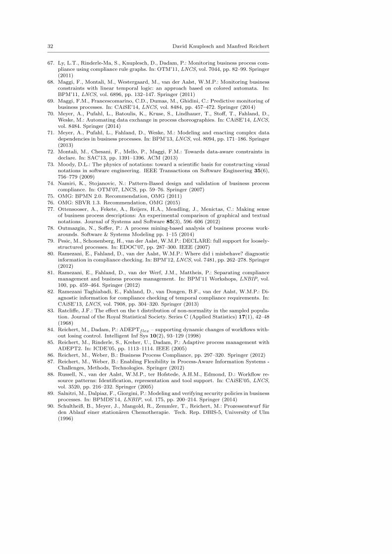
32 David Knuplesch and Manfred Reichert
67. Ly, L.T., Rinderle-Ma, S., Knuplesch, D., Dadam, P.: Monitoring business process com-pliance using compliance rule graphs. In: OTM’11, LNCS, vol. 7044, pp. 82–99. Springer(2011)
68. Maggi, F., Montali, M., Westergaard, M., van der Aalst, W.M.P.: Monitoring businessconstraints with linear temporal logic: an approach based on colored automata. In:BPM’11, LNCS, vol. 6896, pp. 132–147. Springer (2011)
69. Maggi, F.M., Francescomarino, C.D., Dumas, M., Ghidini, C.: Predictive monitoring ofbusiness processes. In: CAiSE’14, LNCS, vol. 8484, pp. 457–472. Springer (2014)
70. Meyer, A., Pufahl, L., Batoulis, K., Kruse, S., Lindhauer, T., Stoff, T., Fahland, D.,Weske, M.: Automating data exchange in process choreographies. In: CAiSE’14, LNCS,vol. 8484. Springer (2014)
71. Meyer, A., Pufahl, L., Fahland, D., Weske, M.: Modeling and enacting complex datadependencies in business processes. In: BPM’13, LNCS, vol. 8094, pp. 171–186. Springer(2013)
72. Montali, M., Chesani, F., Mello, P., Maggi, F.M.: Towards data-aware constraints indeclare. In: SAC’13, pp. 1391–1396. ACM (2013)
73. Moody, D.L.: The physics of notations: toward a scientific basis for constructing visualnotations in software engineering. IEEE Transactions on Software Engineering 35(6),756–779 (2009)
74. Namiri, K., Stojanovic, N.: Pattern-Based design and validation of business processcompliance. In: OTM’07, LNCS, pp. 59–76. Springer (2007)
75. OMG: BPMN 2.0. Recommendation, OMG (2011)76. OMG: SBVR 1.3. Recommendation, OMG (2015)77. Ottensooser, A., Fekete, A., Reijers, H.A., Mendling, J., Menictas, C.: Making sense
of business process descriptions: An experimental comparison of graphical and textualnotations. Journal of Systems and Software 85(3), 596–606 (2012)
78. Outmazgin, N., Soffer, P.: A process mining-based analysis of business process work-arounds. Software & Systems Modeling pp. 1–15 (2014)
79. Pesic, M., Schonenberg, H., van der Aalst, W.M.P.: DECLARE: full support for loosely-structured processes. In: EDOC’07, pp. 287–300. IEEE (2007)
80. Ramezani, E., Fahland, D., van der Aalst, W.M.P.: Where did i misbehave? diagnosticinformation in compliance checking. In: BPM’12, LNCS, vol. 7481, pp. 262–278. Springer(2012)
81. Ramezani, E., Fahland, D., van der Werf, J.M., Mattheis, P.: Separating compliancemanagement and business process management. In: BPM’11 Workshops, LNBIP, vol.100, pp. 459–464. Springer (2012)
82. Ramezani Taghiabadi, E., Fahland, D., van Dongen, B.F., van der Aalst, W.M.P.: Di-agnostic information for compliance checking of temporal compliance requirements. In:CAiSE’13, LNCS, vol. 7908, pp. 304–320. Springer (2013)
83. Ratcliffe, J.F.: The effect on the t distribution of non-normality in the sampled popula-tion. Journal of the Royal Statistical Society. Series C (Applied Statistics) 17(1), 42–48(1968)
84. Reichert, M., Dadam, P.: ADEPTflex – supporting dynamic changes of workflows with-out losing control. Intelligent Inf Sys 10(2), 93–129 (1998)
85. Reichert, M., Rinderle, S., Kreher, U., Dadam, P.: Adaptive process management withADEPT2. In: ICDE’05, pp. 1113–1114. IEEE (2005)
86. Reichert, M., Weber, B.: Business Process Compliance, pp. 297–320. Springer (2012)87. Reichert, M., Weber, B.: Enabling Flexibility in Process-Aware Information Systems -
Challenges, Methods, Technologies. Springer (2012)88. Russell, N., van der Aalst, W.M.P., ter Hofstede, A.H.M., Edmond, D.: Workflow re-
source patterns: Identification, representation and tool support. In: CAiSE’05, LNCS,vol. 3520, pp. 216–232. Springer (2005)
89. Salnitri, M., Dalpiaz, F., Giorgini, P.: Modeling and verifying security policies in businessprocesses. In: BPMDS’14, LNBIP, vol. 175, pp. 200–214. Springer (2014)
90. Schultheiß, B., Meyer, J., Mangold, R., Zemmler, T., Reichert, M.: Prozessentwurf furden Ablauf einer stationaren Chemotherapie. Tech. Rep. DBIS-5, University of Ulm(1996)
A Visual Language for Modeling Business Process Compliance Rules 33
91. Schultheiß, B., Meyer, J., Mangold, R., Zemmler, T., Reichert, M., Dadam, P., Kreien-berg, R.: Prozessentwurf am Beispiel eines Ablaufs aus dem OP-Bereich - Ergebnisseeiner Analyse an der Universitatsfrauenklinik Ulm. Tech. Rep. DBIS-6, University ofUlm (1996)
92. Schultheiß, B., Meyer, J., Mangold, R., Zemmler, T., Reichert, M., Dadam, P., Kreien-berg, R.: Prozessentwurf fur den Ablauf einer ambulanten Chemotherapie. Tech. Rep.DBIS-7, University of Ulm (1996)
93. Semmelrodt, F.: Modellierung klinischer Prozesse und Compliance Regeln mittelsBPMN 2.0 und eCRG. Master Thesis, Ulm University, Germany (2013)
94. Semmelrodt, F., Knuplesch, D., Reichert, M.: Modeling the resource perspective of busi-ness process compliance rules with the extended compliance rule graph. In: BPMDS’14,LNBIP, vol. 175, pp. 48–63. Springer (2014)
95. Sunkle, S., Kholkar, D., Kulkarni, V.: Toward better mapping between regulationsand operational details of enterprises using vocabularies and semantic similarity. In:CAiSE’15 Forum, pp. 229–236. CEUR-WS (2015)
96. Svahnberg, M., Aurum, A., Wohlin, C.: Using students as subjects - an empirical eval-uation. In: ESEM’08, pp. 288–290. ACM (2008)
97. Turetken, O., Elgammal, A., van den Heuvel, W.J., Papazoglou, M.: Capturing compli-ance requirements: A pattern-based approach. IEEE Software pp. 29–36 (2012)
98. Zasada, A., Fellmann, M.: A pattern-based approach to transform natural text fromlaws into compliance controls in the food industry. In: LWA’15 Workshops, pp. 230–238. CEUR-WS (2015)
99. Zugal, S., Soffer, P., Haisjackl, C., Pinggera, J., Reichert, M., Weber, B.: Investigatingexpressiveness and understandability of hierarchy in declarative business process models.Software and System Modeling 14(3), 1081–1103 (2015)