Embed Size (px)
Citation preview

2006-922: A VEHICLE DRIVABLE BY A LAPTOP PC
Krisztian Dancs, University of North Florida
Vanja Gadzic, University of North Florida
Tyler Dao, University of North Florida
Truong Nguyen, University of North Florida
Chiu Choi, University of North FloridaDr. Choi received his Ph.D. degree in electrical and computer engineering from the University ofCalifornia, Santa Barbara. He obtained several years of engineering experience in the industrybefore beginning his Ph.D. study. He is currently a Professor in the Division of Engineering,University of North Florida. He has strong interest in undergraduate electrical engineeringeducation. His teaching interests include control systems, microcontroller applications, digitalsystem design, electromagnetics, signals and systems, circuit analysis, and others. His researchinterests include microcontroller-based system design, computational algorithms for controls, andcontrol theory. Dr. Choi is a registered Professional Engineer (Florida).
© American Society for Engineering Education, 2006
Page 11.139.1

A Vehicle Drivable by a Laptop PC
Abstract
This paper describes the details of converting a regular vehicle into a vehicle that is drivable by a
laptop PC. The work was done as a design project in the first controls course in our curriculum.
The students applied the knowledge that they gained through the controls course and the
microcontroller course to design and built the controllers and the actuators that facilitated the
driving of the vehicle by a laptop PC. The vehicle was a 1993 Geo Metro. Initially this vehicle
was a five speed manual transmission car. It was converted into an automatic transmission
vehicle. This allowed easier control of gear shifting by the PC. Futher modification to the car
was done. The original steering wheel, the covering of the transmission lever, and front car seats
were removed. This allowed the installation of the drive mechanism. For each of the four
operations of steering, accelerating, braking, and transmission gear shifting, a set of drive
mechanism was designed and built. Each drive mechanism consisted of an acutuator driven by a
dc motor, motor driver chips, and sensors. The sensors sensed the positions and the signals were
fedback to a microcontroller that controlled the actuators. The microcontroller used was the
Freescale MC68HC12B. Special attention was paid to safety in this project. Careful
consideration was given to the scenario of loosing control of the vehicle during testing. Safety
procedure was developed and followed strictly. No accident occured during the testing. The
modified vehicle was tested in an empty parking lot after notification of authorities. In the test
the laptop took the keyboard inputs for accelerating, braking, steering, and gear shifting and
issued control signals to the drive electronics. The vechicle responded accordingly as designed.
When the speed of the vehicle was kept less than 10 miles per hour, it was maneuverable around
the testing area easily. Trying to drive the vehicle from a keyboard was somewhat difficult at
high speed and it took time to learn. The work performed in this project can be used for a
follow-up project, which goal is to remotely control the vehicle.
I. Introduction Page 11.139.2

One of the goals of this design project is to explore the possibility of performing all drive
controls of an automobile by a laptop computer. A block diagram of our design is shown in
Figure 1.
Keyboard
Inputs
Figure 1: Vehicle Drive Control Block Diagram
The laptop receives keyboard inputs from the user. The inputs are right turn, left turn,
acceleration, braking, forward, reverse, and other commands. These keyboard inputs are read by
a 68HC12 microcontroller[1-7]
. The microcontroller will then control the steering wheel, the
brake, the gas pedal, and the transmission lever through mechanical designs actuated by dc
motors. The positions of the brake pedal, gas pedal, and transmission lever are sensed by
potentiometers. The signals were fedback to the microcontroller for acheiving accurate position
feedback control[9-17]
.
Page 11.139.3

The automobile used in the experimentation was a 1993 Geo Metro. Major modifications were
done on it so that it could be controlled by the laptop computer. First, the original five speed
manual transmission was converted to automatic transmission so that gear shifting could be
implemented more easily.
Second, the casing for the transmission lever were removed. and mechanical parts and another
motor were connected to the lever so that it could shift between Parking, Reverse, Neutral, and
Forward.
Third, the original steering wheel was welded to a flywheel and other mechanical parts. The
gears of the flywheel were coupled to a gearhead motor controlled by the microcontroller. This
allowed the control of steering by the microcontroller.
Lastly, mechanical parts and a seperate motor were connected to the brake and gas pedals so that
pressure could be applied on the brake through the dc motors.
The main purpose of this project is to provide experimental data for the analysis of the control
techniques and to investigate the possibility of remote control of the vehicle in the future. The
participation in the Department of Defense’s DARPA Grand Challenge is out of our range at this
point.
The rest of this paper is organized as follows: the design approach is described in the next four
sections and it covers the dc motor selection, motor driver selection, braking control, acceleration
control, transmission control, and steering control. Resources used in the microcontroller and
programming is described in Section VI. Testing results are described in Section VII and
concluding remarks are provided in Section VIII.
II. DC Motor Selection
Based on the available budget, cordless drill dc motors were selected in drive control systems. A
photo of the actual cordless drill used in this project is shown in Figure 2. These dc motors are
gearhead dc motors. The motor shafts of this type of motors are coupled to the output load shafts
Page 11.139.4

through specific gearing systems. The purpose of the gearing system is to increase the torque
performance. These motors operate on 18 V power pack batteries. At no load, it drains 1.5 to 2.0
A. When the shaft was locked a current measurement indicated 5.6 to 6.0 A of maximum current
drawn from the batteries. The scenario of locked shaft seldom occurred in our project but in our
design we tried to accommodate this case. The power requirements of our design were based on
these measurements.
load-coupling shaft internal gearhead
Figure 2: Cordless Gearhead DC Drill
Each dc motor was removed from the drill casing and was mounted into the vehicle drive
systems. Proper mounting brackets were fabricated to hold the motors in place so that they could
withstand vibrations caused by a moving vehicle.
III. DC Motor Driver IC Selection and Operation Page 11.139.5

The next step was to select dc motor driver chips for controlling the dc motors. The criteria were
that the chips could deliver 3 A of current continuously and 6 A of current momentarily to the
motor up to an operating voltage of 20 V and that it could be easily controlled by the Freescale’s
MC68HC12 microcontrollers. The LMD18200T[8]
manufacutred by National Semiconductor
Corporation was chosen. The LMD18200T is an H-bridge dc motor driver. It is capable of
providing 3 A of current continuously and 6 A of current momentarily to any inductive load up
to an operating voltage of 55 V.
The particular package selected was the 11-lead TOS-220 package as shown in Figure 3. The
TOS-220 package allows easy mounting of heat sink to it and therefore has better heat
dissipation capability over the other available packages. These motor driver chips were used to
control all the dc motors installed into the vehicle for steering, braking, accelerating, and
transmission shifting.
Figure3: LMD18200T TOS-220
The operation of this chip in our project is briefly described as follows: we used the simple,
locked anti-phase PWM mode. In this mode, the direction and amplitude of the control signal are
embedded into the PWM signal. A pinout diagram of the configuration used is shown in Figure
4. A 50% duty-cycle PWM signal represents zero drive.
A duty cycle more than 50 percent will drive the motor in one direction. The higher the duty
cycle the more is the current delivered to the motor.
Page 11.139.6

A duty cycle less than 50% will drive the motor in the opposite direction. The smaller the duty
cycle the more is the current delivered to the motor in the opposite direction.
Figure 4: DC Motor Control Circuit
IV. Braking, acceleration, and transmission Control
The design of the braking, acceleration, and transmission control were similar. It was based on
the classical position feedback control method. A linear potentiometer was attached to the
moving part of each mechanical unit to provide a voltage feedback to the MC68HC12 for
sensing the positions. For braking, a potentiometer sensed the position of the brake pedal. For
acceleration, another potentiometer sensed the position of the gas pedal. For transmission, a
third potentiometer sensed the position of the transmission at Park, Reverse, Neutral, and Drive.
The braking, acceleration, and transmission control are shown in Figures 5, 6, and 7,
respectively.
In each of the three controls, each dc motor was mounted to a pivoting mounting bracket. The
motor load shaft was attached to a threaded rod which length was different for different system.
A female threaded pivoting joint was attached to each mechanical unit (brake and acceleration
pedals and transmission stick). The threaded rod linked through the female joint, just like a bolt
Page 11.139.7

through a nut. When the motor was rotating, the threaded rod rotated in the same direction. The
rod applied force on the female joint that pushed a pedal or the stick up or down depending on
the direction of rotation. The potentiometers sensed the positions. The potentiometer signals
were read by the microcontroller. When the desired positions were reached, the microcontroller
would stop the motors. Since the pedals and the transmission lever did not move in a linear
manner but more in an angular motion, the voltage readings from the linear potentiometer were
nonlinear.
aluminum arm potentiometer LMD18200T connections
female joint treaded drive rod gearhead/slippage pivoting bracket
Figure 5: Braking Control
Test was conducted on these three systems (braking, acceleration, and transmission). The data
collected showed that each motor could be powered from the vehicle’s 12 V battery. The average
Page 11.139.8
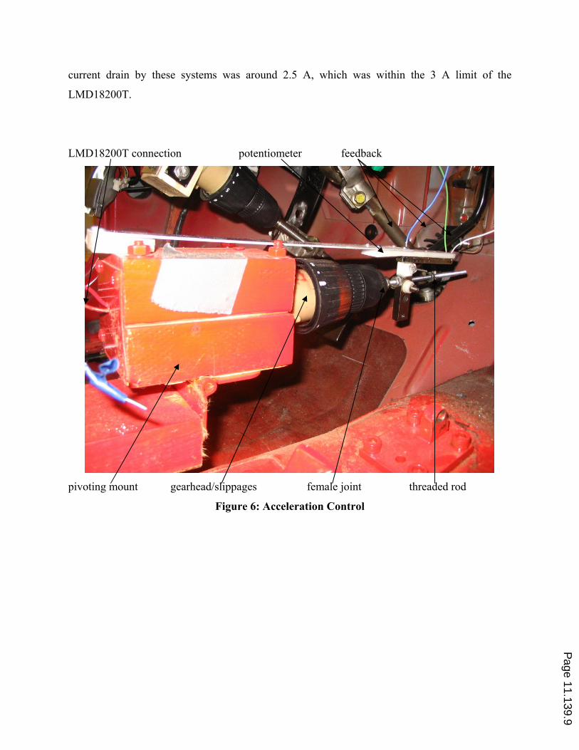
current drain by these systems was around 2.5 A, which was within the 3 A limit of the
LMD18200T.
LMD18200T connection potentiometer feedback
pivoting mount gearhead/slippages female joint threaded rod
Figure 6: Acceleration Control
Page 11.139.9

potentiometer feedback female joint threaded rod gearhead/slippage dc motor
Figure 7: Transmission Control
V. Steering Control
This system was one of the most difficult to implement. Finding a way to attach the dc motor to
the steering column and to have enough torque to turn it left or right was no easy task. A simple
solution was devised where a flywheel (as shown in Figure 8) together with its starter gearhead
linkage (as shown in Figure 9) were used. The flywheel was welded to the steering wheel itself
and the starter gearhead was welded to the dc motor’s drive shaft (Figure 9). The dc motor drove
the flywheel so as to turn the car left or right. With a large number of teeth on the flywheel, it
provided additional mechanical advantage while the starter gearhead already had very good gear
ratio per turns. The torque was much increased and the dc motor was sufficient to drive the
steering column. However this came at price, because increasing the torque form the motor shaft Page 11.139.10
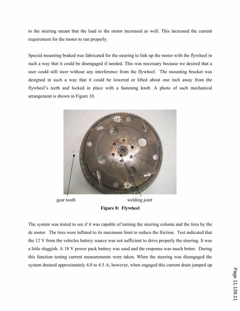
to the steering meant that the load to the motor increased as well. This increased the current
requirement for the motor to run properly.
Special mounting braked was fabricated for the steering to link up the motor with the flywheel in
such a way that it could be disengaged if needed. This was necessary because we desired that a
user could still steer without any interference from the flywheel. The mounting bracket was
designed in such a way that it could be lowered or lifted about one inch away from the
flywheel’s teeth and locked in place with a fastening knob. A photo of such mechanical
arrangement is shown in Figure 10.
gear tooth welding joint
Figure 8: Flywheel
The system was tested to see if it was capable of turning the steering column and the tires by the
dc motor. The tires were inflated to its maximum limit to reduce the friction. Test indicated that
the 12 V from the vehicles battery source was not sufficient to drive properly the steering. It was
a little sluggish. A 18 V power pack battery was used and the response was much better. During
this function testing current measurements were taken. When the steering was disengaged the
system drained approximately 4.0 to 4.5 A; however, when engaged this current drain jumped up Page 11.139.11

to as much as 7.5 A. It was a clear indication that one single LMD18200T would not be able to
provide this amount of current.
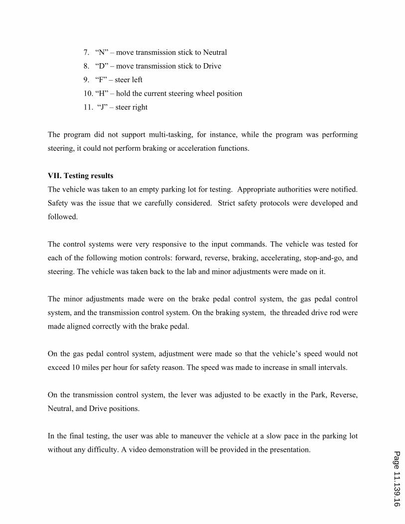
To solve the current problem of the steering system, it was decided to use two LMD18200Ts
connected in parallel and to use a separate power source of 18 V battery, which was from the
original drill. The connection of the two LMD18200Ts is shown in Figure 11. This configuration
solved the current problem and the steering was much improved.
It was intended to use a hall-effect sensor (ATS612LSB by Allegro) to sense the position of the
flywheel and to use the input capture method supported by MC68HC12 microcontroller to
determine how much the steering column turned and used that as the feedback signal. However,
due to insufficient time, this was not implemented.
Flywheel linkage
dc motor dc motor gearhead shaft linkage starter gearhead
Figure 9: DC Motor w/starter gearhead
Page 11.139.12
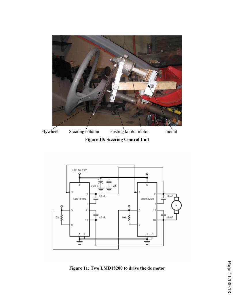
Flywheel Steering column Fasting knob motor mount
Figure 10: Steering Control Unit
Figure 11: Two LMD18200 to drive the dc motor
Page 11.139.13

VI. Resources used in the microcontroller and programming
This system consists of four subsystems, as mention earlier, controlled by the MC68HC
microprocessor from a user’s consol (laptop) to activate different functions of the vehicle.
Four PWMs of the microcontroller were used for driving the braking control system, the
acceleration control system, the transmission control system, and the steering control system.
Three analog-to-digital converters of the microcontroller were used for reading the
potentiometers of the braking control system, the acceleration control system, and the
transmission control system. The microcontroller, the motor drivers and other components were
mounted on a protoboard, which was attached to the dashboard as shown in Figures 12 and 13.
Ignition steering subsystem
starter cut-off switches 68HC12B Subsystems
Figure 12: System Control Unit
Page 11.139.14

Figure 13: Control systems in the vehicle
Programming implementation was decided to be in assembly to increase performance and to
minimize memory usage. The assembly program accepted keyboard inputs from the user at the
consol (laptop). Each keyboard input was evaluated and a corresponding subroutine within the
program was called to activate one of the four control systems. Eleven commands were devised
to control the vehicle’s functions:
1. “A” – accelerate (depress gas pedal)
2. “S” – decelerate (release gas pedal)
3. “B” – brake (apply brake)
4. “U” – release brake
5. “P” – move transmission stick to Park
6. “R” – move transmission stick to Reverse
Page 11.139.15
7. “N” – move transmission stick to Neutral
8. “D” – move transmission stick to Drive
9. “F” – steer left
10. “H” – hold the current steering wheel position
11. “J” – steer right
The program did not support multi-tasking, for instance, while the program was performing
steering, it could not perform braking or acceleration functions.
VII. Testing results
The vehicle was taken to an empty parking lot for testing. Appropriate authorities were notified.
Safety was the issue that we carefully considered. Strict safety protocols were developed and
followed.
The control systems were very responsive to the input commands. The vehicle was tested for
each of the following motion controls: forward, reverse, braking, accelerating, stop-and-go, and
steering. The vehicle was taken back to the lab and minor adjustments were made on it.
The minor adjustments made were on the brake pedal control system, the gas pedal control
system, and the transmission control system. On the braking system, the threaded drive rod were
made aligned correctly with the brake pedal.
On the gas pedal control system, adjustment were made so that the vehicle’s speed would not
exceed 10 miles per hour for safety reason. The speed was made to increase in small intervals.
On the transmission control system, the lever was adjusted to be exactly in the Park, Reverse,
Neutral, and Drive positions.
In the final testing, the user was able to maneuver the vehicle at a slow pace in the parking lot
without any difficulty. A video demonstration will be provided in the presentation.
Page 11.139.16

VIII. Concluding remarks
The project goals were met. The team was able to design a vehicle control system that can take
keyboard input commands from a laptop and manipulate the vehicle accordingly in forward,
reverse, braking, accelerating, stop-and-go, and steering left and right. During field testing it
was learned that trying to drive a vehicle form a keyboard was somewhat difficult and took time
to learn. However if the speed of the vehicle was kept less than 10 miles per hour, it could be
easily maneuvered around the testing area. Remote control of the car is possible by replacing the
laptop interface with wireless interface to the 68HC12.
Some improvements are need. First, the steering response time needed to be shortened if speed
was allowed to increase. Second, incorporate real time multitasking so that accelerating (or
braking), steering, and transmission control can be done at the same time.
Bibliography
1. CPU12 Reference Manual, Motorola DigitalDNA, 2000
2. M68HC12B Family Advanced Information Reference Manual, Motorola Digital DNA ,
2001.
3. CME-12B/BC manual, Axiom Manufacturing, 2000.
4. Todd Morton, Embedded Microcontrollers, Prentice Hall, 2001,
5. Cady, et. al, Software and Hardware Engineering Motorola M68HC12, Oxford, 2002.
6. Haskell, Design of Embedded Systems HC11/12 Microcontrollers, Prentice Hall, 2000
7. Barrett and Pack, Embedded Systems, Pearson Prentice Hall, 2005
8. LMD18200T data sheets: http://cache.national.com/ds/LM/LMD18200.pdf
9. Franklin, et. al, Feedback Control of Dynamic Systems, 3rd
Ed., Addison Wesley.
10. Dorf and Bishop, Modern Control Systems, 9th Ed., Prentice Hall.
11. Norman S. Nise, Control Systems Engineering, 4th ed., John Wiley & Sons, Inc.
12. Stefani, et al., Design of Feedback Control Systems, 4th
Ed., Oxford.
13. Dorsey, Continuous and Discrete Control Systems, Mc Graw Hill.
14. Goodman, et al., Control System Design, Prentice Hall
15. Phillips and Harbor, Feedback Control Systems, 3rd
Ed., Prentice Hall.
16. Driels, Linear Control Systems Engineering, McGraw Hill, 1996.
17. Ogata, Modern Control Engineering, 4th
ed., Prentice Hall, 2002.
Page 11.139.17