Embed Size (px)
Citation preview

J. Fluid Mech. (1998), vol. 360, pp. 121–140. Printed in the United Kingdom
c© 1998 Cambridge University Press
121
A universal time scale for vortex ring formation
By M O R T E Z A G H A R I B1, E D M O N D R A M B O D1
AND K A R I M S H A R I F F2
1Graduate Aeronautical Laboratories, California Institute of Technology, Pasadena,CA 91125, USA
2NASA Ames Research Center, Moffett Field, CA 94035, USA
(Received 20 December 1996 and in revised form 10 November 1997)
The formation of vortex rings generated through impulsively started jets is studiedexperimentally. Utilizing a piston/cylinder arrangement in a water tank, the velocityand vorticity fields of vortex rings are obtained using digital particle image velocimetry(DPIV) for a wide range of piston stroke to diameter (L/D) ratios. The results indicatethat the flow field generated by large L/D consists of a leading vortex ring followedby a trailing jet. The vorticity field of the leading vortex ring formed is disconnectedfrom that of the trailing jet. On the other hand, flow fields generated by small strokeratios show only a single vortex ring. The transition between these two distinct statesis observed to occur at a stroke ratio of approximately 4, which, in this paper, isreferred to as the ‘formation number’. In all cases, the maximum circulation thata vortex ring can attain during its formation is reached at this non-dimensionaltime or formation number. The universality of this number was tested by generatingvortex rings with different jet exit diameters and boundaries, as well as with variousnon-impulsive piston velocities. It is shown that the ‘formation number’ lies in therange of 3.6–4.5 for a broad range of flow conditions. An explanation is providedfor the existence of the formation number based on the Kelvin–Benjamin variationalprinciple for steady axis-touching vortex rings. It is shown that based on the measuredimpulse, circulation and energy of the observed vortex rings, the Kelvin–Benjaminprinciple correctly predicts the range of observed formation numbers.
1. IntroductionVortex rings are a particularly fascinating fluid mechanical phenomenon. From
starting jets to volcanic eruptions or the propulsive action of some aquatic creatures,as well as the discharge of blood from the left atrium to the left ventricular cavity inthe human heart, vortex rings (or puffs) can be identified as the main flow feature.The generation, formation, and evolution of vortex rings have been the subject ofnumerous experimental, analytical and numerical studies. The reviews of Shariff &Leonard (1987), and Lim & Nickels (1995) describe much of the current understandingof vortex ring phenomena as well as some unresolved issues.
In the laboratory, vortex rings can be generated by the motion of a piston pushinga column of fluid of length L through an orifice or nozzle of diameter D. This resultsin the separation of a boundary layer at the edge of the orifice or nozzle and itssubsequent spiral roll-up. The main focus of vortex ring studies in the past has beento describe the evolution of the ring’s size, position, and circulation. For example,Maxworthy (1977), Didden (1979), Auerbach (1987a), Glezer (1988), and Glezer &

122 M. Gharib, E. Rambod and K. Shariff
Coles (1990) studied some of the fundamental aspects of vortex ring formation as wellas vortex ring trajectory and evolution. Glezer (1988) considered a few different pistonvelocities as a function of time known as the ‘velocity program’. Didden’s (1979) workhas been very popular among vortex ring researchers, since it provides a clear pictureof the role of internal and external boundary layers in the formation process andcirculation of the vortex ring. Utilizing similarity theory, Saffman (1978) and Pullin(1979) obtained expressions for the vortex ring trajectory, circulation and its vorticitydistribution. Weigand & Gharib (1997) revisited the vortex ring problem using digitalparticle image velocimetry (DPIV). They showed that vortex rings generated by apiston/cylinder arrangement possess a Gaussian vorticity distribution in their coreregion. James & Madnia (1996) present a numerical study of vortex ring formationfor different generator configurations. They concluded that the total circulation andimpulse in the flow field of the ring are approximately the same for nozzles with andwithout a vertical wall at the nozzle exit plane.
The piston/cylinder arrangement has been extensively used to address the problemof vortex ring generation. However, except for the investigations of Baird, Wairegi& Loo (1977) and Glezer (1988), all of the available experimental, analytical andnumerical investigations of vortex rings use small stroke ratios (L/D). Glezer’s (1988)work focused mainly on mapping the boundaries for the laminar to turbulent transi-tion as a function of L/D, while Baird et al.’s work addresses the role of the impulseof the vortex ring in the formation process and presents some flow visualizationobservations, which we will discuss later in this paper. Therefore, to the best of ourknowledge, the flow behaviour of vortex rings that can be generated with large strokeratios (L/D) has not been examined before.
In particular, let us consider the question of the largest circulation that a vortexring can achieve by increasing L/D, keeping the average piston velocity fixed. Ingeneral, the vorticity flux provided by the separated shear layer is the main source ofvorticity for the forming vortex ring (Didden 1979). Therefore, a termination of thepiston motion inhibits the flow of shear layer vorticity and thus its accumulation inthe core region of the vortex ring. In this case, we should expect the circulation inthe vortex formed to be approximately equal to the discharged circulation from thenozzle or orifice. In the limit of large L/D, the question arises about the existenceof a limiting process which would inhibit the vortex ring from evolving (growing)indefinitely while still being fed by the vorticity emanating from the tube. In otherwords, for a given geometry, is there an upper limit to the maximum circulation thata vortex ring can acquire?
The purpose of this paper is to address this question. To do this, we must observesome of the global features of the vortex ring formation such as its velocity andthe vorticity fields from which vortex ring circulation as a function of L/D can beobtained. We will present experimental evidence to prove the existence of such alimiting process.
2. Experimental setupFigure 1 shows a schematic of the experimental setup. Experiments were conducted
in a water tank using a constant-head tank in conjunction with a computer-controlledflow monitoring valve. Vortex rings are generated by allowing the flow from theconstant-head tank to drive a piston that pushes fluid out of a sharp-edged cylindricalnozzle into the surrounding fluid. The x-axis coincides with the centreline of the vortexring generator, and the nozzle-exit plane is located in the plane x = 0.

A universal time scale for vortex ring formation 123
Dump tank
Overflow
Pump
Constant-head tank
Controlvalve
Computer controller
Ultrasonicflow meter
Water tank
D
L
α
Figure 1. General schematic of vortex ring generator.
The main cylindrical nozzle had an inner diameter (D) of 2.54 cm. The outercontour of the cylindrical nozzle was shaped to form a wedge with a tip angle ofα = 20◦ and a length of 1.5 cm. In order to study the effect of the exit geometry,α was increased to 90◦ by simply mounting a vertical plate at the nozzle exit plane.In order to generate smaller vortex rings, a smaller nozzle with an inner diameter of1.63 cm and an L/D of 12 was partially inserted inside the main nozzle. With thisconfiguration, the main nozzle’s piston action can be used to drive the fluid throughthe smaller nozzle.
A computer-controlled variable-area valve controlled the flow rate from a constant-head tank which in turn controlled the velocity program of the piston. An ultrasonicflow meter (Transonic Systems, Inc., Model T-208) was used to monitor the fluidvolume displaced by the piston motion. The overall length of the cylinder limited themaximum stroke of the piston to (L/D)max = 15 and the maximum acceleration anddeceleration to |a|max ≈ 250 cm s−2. Figure 2 presents typical piston velocities versustime for one case of impulsive motion and two cases of different ramp profiles. Thecomputer control provides precise timing and synchronization of various events witha time resolution of approximately 10−3 s. These events include, for example, vortexring generation and initialization of measurement processes, such as ultrasonic flowmetering and DPIV.
Fluorescent dye as a fluid marker, in conjunction with a laser light sheet, was usedto make the vortex ring visible. For the purposes of DPIV, the flow was seeded withneutrally buoyant silver-coated glass spheres with an average diameter of 14 ± 5 µmand illuminated by a sheet of laser light with a thickness of approximately 0.1 cm.
The technique of DPIV (Willert & Gharib 1991), was implemented to map theflow field. DPIV measures the two-dimensional displacement-vector field of particlessuspended in the flow and illuminated by a thin pulsed sheet of laser light. Thepresent experiment used a high-speed version of DPIV that is described in detail byWeigand & Gharib (1997).
The imaging video camera was positioned normal to the measurement plane andrecorded image sequences of particle fields with spatial resolution of 768× 480 pixels.With a typical field of view of 11 × 8 cm, the spatial resolution is 0.23 × 0.23 cm,and the uncertainty in the velocity and vorticity measurement is ±1% and ±3%,respectively.

124 M. Gharib, E. Rambod and K. Shariff
20
15
10
5
0 0.5 1.0 1.5 2.0 2.5 3.0
Time (s)
Impulse Fast ramp Slow ramp
Pis
ton
velo
city
(cm
s–1
)
Figure 2. Piston velocity vs. time for three different acceleration conditions.
3. Parameters governing the vortex ring’s circulation
For a given geometry, the circulation of a vortex ring (Γ ) depends on the historyof the piston velocity up(t), nozzle or orifice diameter (D), kinematic viscosity (ν) anddischarge time (t). The piston stroke (L) is a derived parameter related to up(t) by
L =∫ t
0up(t)dt.
We introduce Up (the running mean of the piston velocity, Up = (1/t∫ t
0updt) as
the suitable velocity scale. The aforementioned set of dimensional parameters canthen be reduced to the non-dimensional piston velocity history Up(t)/Up and totwo non-dimensional parameters Γ/UpD and Upt/D. This non-dimensional time isequivalent to the ratio of length to diameter of the ejected fluid column (strokeratio), i.e. L/D = Upt/D, and will be referred to as the ‘formation time’ in thispaper.
Using the boundary layer assumption, we can show that the vorticity flux fromthe nozzle is approximately equal to U2
m/2 where Um is the maximum velocity withinthe cylinder at the exit plane. For the slug model, which assumes a uniform profile,we have U2
p/2 = U2m/2. However, this assumption will not be valid for large stroke
ratios (L/D), where the velocity profile in the pipe would show acceleration in thecentral region caused by the growth of the boundary layer region (Didden 1979).In this case, one needs to obtain a time history of U2
m and use it to normalizeinstantaneous circulation values. For this reason, formulas suggested by Didden, inwhich circulation is non-dimensionalized by UpD, do not predict the circulation valuefor large L/D values correctly (Shariff & Leonard 1992). Glezer (1988) suggested usingthe kinematic viscosity (ν) to normalize circulation (Γ ) as Γ/ν, which can also beconsidered the Reynolds number of the vortex rings. In the limits of a high Reynoldsnumber, kinematic viscosity should not play a role in the vortex ring’s formationprocess. In this paper, we chose to present the circulation data in its dimensionalform.

A universal time scale for vortex ring formation 125
(a)
(b)
(c)
Figure 3. Visualization of vortex rings at X/D ≈ 9 for (a) Lm/D = 2, Re ≈ Γ/ν ≈ 2800;(b) Lm/D = 3.8, Re ≈ 6000; and (c) Lm/D = 14.5. Picture is taken at Upt/D = L/D = 8. All threecases were generated by an impulsive piston velocity depicted in figure 2.
4. Flow visualizationFigures 3(a), 3(b) and 3(c) show three vortex rings generated by three different
maximum stroke ratios (Lm/D). The vortex rings shown in these pictures are at anapproximate axial position of X ≈ 9D from the nozzle exit. In figure 3(a), Lm/D = 2,while in figure 3(b), Lm/D ≈ 3.8. For the case in figure 3(c), the piston was passingthrough the position L/D ≈ 8 at the time the picture was taken. The piston motionwas only stopped later at Lm/D = 14.5. In all cases, vortices were generated withsimilar impulsive piston motion to that depicted in figure 2.
One striking feature in these pictures is the existence of a trailing jet of fluid behindthe leading vortex ring in figure 3(c) and lack of it in figures 3(a) and 3(b). It appearsthat in figures 3(a) and 3(b) almost all of the discharged fluid has been entrainedinto the vortex ring. However, for the case in figure 3(c), the vortex ring shows aclear separation from the active trailing jet-like region behind it. It is apparent thatthe formation of the vortex ring has been completed and the vorticity is no longerentrained from the shear layer region of the trailing jet. It is interesting to note that thesize of the leading vortex ring in figure 3(c) is approximately the same as that of thevortex ring in figure 3(b) and is larger than that depicted in figure 3(a). Consideringthat the pictures are taken at the same downstream position of X ≈ 9D, this variation
126 M. Gharib, E. Rambod and K. Shariff
in the formation of the rings indicates a fundamental difference in the way that thesethree flows have reached their asymptotic states. A similar phenomenon can be seenin the flow visualization of Baird et al. (1977). But, curiously they do not reportthe distinction in the nature of the vortex rings formed with short and long Lm/Dconditions as presented in figures 5 and 6 of their paper.
From these observations, it is natural to conjecture the existence of a limiting valuefor the formation time (Upt/D) or stroke ratio (L/D), for which vortex rings generatedwith values above this limiting value do not absorb all of the discharged fluid’s massor vorticity. The important point is to identify this limiting value (L/D)lim and alsorelate it to the vortex ring’s velocity and vorticity fields. In this paper, we refer to(L/D)lim as the ‘formation number’.
5. Velocity and vorticity fields of vortex ringsIn figures 4(a, b) and 5(a, b), we present detailed measurements of velocity and
vorticity fields for Lm/D ≈ 2 and Lm/D ≈ 14.5, respectively. These cases correspondto the flow visualizations presented in figures 3(a) and 3(c). In agreement with thevisual observations, the case Lm/D ≈ 2 does not show any noticeable level of vorticityin the trailing region after the formation of the vortex ring. On the other hand, thecase Lm/D = 14.5 shows interesting dynamics in terms of disconnection or ‘pinch-off’of both velocity and vorticity fields of vortex rings from the trailing jet. It is importantto note that the vorticity in the shear layer of the trailing jet ceases to flow into thecore region of the vortex ring once the pinch-off process starts. Instead, the trailingvorticity forms into a series of vortices similar to the Kelvin–Helmholtz instability.
The above observation clearly indicates the occurrence of a pinch-off processwhich causes termination of the vorticity flow into the ring and further increase ofthe circulation level in the ring. From the vorticity contours, one can obtain thetotal discharged circulation by integrating the vorticity contained within the lowestdetectable contours for either positive or negative senses. In our observations, thiscontour level was determined to be at 1 s−1. Also, in the absence of the trailing jet,the total circulation level was not very sensitive to the choice of the level, as longas this was chosen to visually contain the desired vorticity region. However, for thecases where a trailing jet-like region appears, the vortex ring circulation can only bemeasured when a clear separation between vorticity contours of the vortex from thoseof the trailing region exists. In this case, circulation of the vortex was determined ata larger X/D position where the pinch-off process was clearly complete.
6. Circulation of the vortex ring as a function of the maximum stroke ratio(Lm/D) and formation time (Upt/D)
We performed two sets of experiments in order to identify the transition betweenvortex rings with and without trailing jet flow.
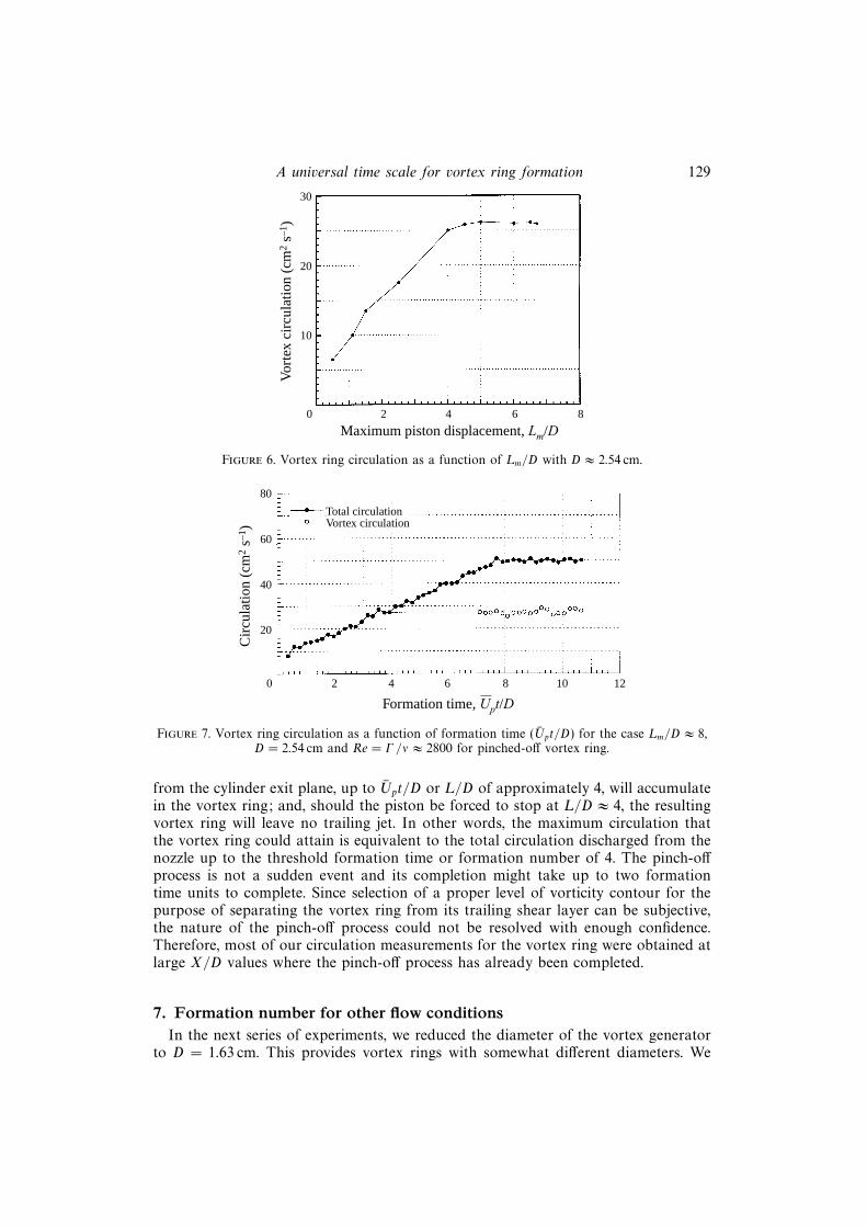
In the first set of experiments, vortex rings were generated by limiting the maximumstroke ratio (Lm/D) to set values in the range of 0.5 to 6.7. Also, for mechanicalreasons, the maximum impulse velocity was limited to 7.5 cm s−1. For each case, themaximum circulation of the vortex formed (of either positive or negative sense) wasmeasured by integrating the vorticity within an iso-vorticity contour (of a given sense)of 1 s−1. The results for circulation vs. maximum stroke ratio (Lm/D) are shown infigure 6.
It is interesting to note that for a given set of flow parameters, the maximum

A universal time scale for vortex ring formation 127
4
2
0
–2
–4
0 2 4 6 8 10 12 14 16
X (cm)
(b)
4
2
0
–2
–4
0 2 4 6 8 10 12 14 16
(a)
4 cm s–1
Y (
cm)
Y (
cm)
Figure 4. (a) Velocity vector and (b) vorticity fields of a vortex ring with Lm/D ≈ 2.
circulation that the vortex ring can attain is reached with Lm/D in the range of 4 to5. Therefore, we should expect the limiting value (L/D)lim or ‘formation number’ toreside in this range.
In the second set of experiments, we measured the circulation emanating from thecylinder and the vortex ring as a function of the formation time† or Upt/D = L/D. Inthese experiments, the piston was impulsively started with Up = 7.5 cm s−1 and wasstopped when L/D ≈ 8 (i.e. for this case Lm/D ≈ 8). The main difference between thesecond and the first set of experiments is that in the first set the formation processwas not interrupted by the stopping of the piston at the end of each run. For this
† Non-dimensional time or Upt/D for each case is equivalent to the stroke ratio (L/D). For the
points after the piston stops, we used the last value of Up in calculating the non-dimensional time.

128 M. Gharib, E. Rambod and K. Shariff
4
2
0
–2
–4
0 2 4 6 8 10 12 14 16
X (cm)
(b)
4
2
0
–2
–4
0 2 4 6 8 10 12 14 16
(a)
4 cm s–1
Y (
cm)
Y (
cm)
Figure 5. (a) Velocity vector and (b) voriticity field of a vortex ring with Lm/D ≈ 14.5corresponding to case (c) in figure 3.
case, the total circulation and the maximum circulation of the vortex ring after itsformation was measured at each time step.
In figure 7, the maximum circulation of a vortex ring is shown by open circlesand the total circulation by solid circles. As is expected, after L/D ≈ 8 (when thepiston stops) the total circulation remains at a constant level of 50 cm2 s−1. Thevortex ring formed shows a circulation level of 28 ± 1 cm2 s−1 corresponding to aReynolds number (Γ/ν, where Γ is the circulation of the pinched-off vortex ring) ofapproximately 2800. As is shown by a straight line on the plot, at a formation time ofapproximately 4, the vortex generator has produced a circulation level of 28 cm2 s−1,which is equivalent to that of the vortex ring formed.
From these observations, we can infer that only the vorticity that has emanated
A universal time scale for vortex ring formation 129
30
20
10
0 2 4 6 8
Maximum piston displacement, Lm/D
Vor
tex
circ
ulat
ion
(cm
2 s–1
)
Figure 6. Vortex ring circulation as a function of Lm/D with D ≈ 2.54 cm.
80
20
0 2 4 6 8 10 12
Formation time, Upt/D
Cir
cula
tion
(cm
2 s–1
)
40
60
Total circulationVortex circulation
Figure 7. Vortex ring circulation as a function of formation time (Upt/D) for the case Lm/D ≈ 8,D = 2.54 cm and Re = Γ/ν ≈ 2800 for pinched-off vortex ring.
from the cylinder exit plane, up to Upt/D or L/D of approximately 4, will accumulatein the vortex ring; and, should the piston be forced to stop at L/D ≈ 4, the resultingvortex ring will leave no trailing jet. In other words, the maximum circulation thatthe vortex ring could attain is equivalent to the total circulation discharged from thenozzle up to the threshold formation time or formation number of 4. The pinch-offprocess is not a sudden event and its completion might take up to two formationtime units to complete. Since selection of a proper level of vorticity contour for thepurpose of separating the vortex ring from its trailing shear layer can be subjective,the nature of the pinch-off process could not be resolved with enough confidence.Therefore, most of our circulation measurements for the vortex ring were obtained atlarge X/D values where the pinch-off process has already been completed.
7. Formation number for other flow conditionsIn the next series of experiments, we reduced the diameter of the vortex generator
to D = 1.63 cm. This provides vortex rings with somewhat different diameters. We

130 M. Gharib, E. Rambod and K. Shariff
80
20
0 2 4 6 8 10 12
Formation time, Upt/D
Cir
cula
tion
(cm
2 s–1
)
40
60
Total circulationVortex circulation
Figure 8. Vortex ring circulation as a function of formation time (Upt/D) for the case Lm/D ≈ 6,D = 1.63 and Re = Γ/ν ≈ 2800 for the pinched-off vortex ring.
80
20
0 2 4 6 8 10 12
Formation time, Upt/D
Cir
cula
tion
(cm
2 s–1
)
40
60
Total circulationVortex circulation
Figure 9. Vortex ring circulation as a function of formation time (Upt/D) for the case ofLm/D ≈ 6, D = 1.63 cm with the wall (α = 90◦). Re = Γ/ν ≈ 2800 for the pinched-off vortex ring.
also adjusted the maximum impulsive piston velocity in order to keep the Reynoldsnumber in the same range as in the case with a diameter of 2.54 cm. It can be seenin figure 8 that with a formation number of about 3.8 ± 0.2, the total dischargedcirculation reaches the maximum circulation of the vortex ring. This value of theformation number is very close to that obtained for the large-diameter vortex ringcase presented in figure 7. Next, a solid wall was installed at the plane of the nozzleexit. Therefore, the angle α (shown in figure 1), was increased to 90◦. Figure 9 showsthat the maximum level of circulation for the rings decreased slightly which resultedin a lower value of the formation number (Upt/D ≈ 3.6). This reduction can beattributed to the opposite-sign vorticity generated in the secondary boundary layeron the outside wall and its entrainment by the vortex ring. However, it is interestingthat the drastic nature of the change in the boundary condition has not resulted inany major shift in the formation number.
In the next set of experiments, we raised the maximum impulsive piston velocityto 15 cm s−1 (figure 2). This provides us with a vortex ring at a Reynolds number

A universal time scale for vortex ring formation 131
120
0 3 6 9 12 15
Formation time, Upt/D
Cir
cula
tion
(cm
2 s–1
)
60
Total circulationVortex circulation
180
240
Figure 10. Vortex ring circulation as a function of formation time (Upt/D) for the case ofimpulsive piston motion, Lm/D ≈ 14.5, D = 2.54 cm and Re = Γ/ν ≈ 6000 for the pinched-offvortex ring.
of 6000, which is twice that in the previous case. This case also corresponds tothe flow visualization images in figure 3(c) and velocity and vorticity field seriesin figure 5. Figure 10 presents the total circulation and vortex ring circulation vs.formation time for this case. A formation number of approximately 4.2 can beassociated with the time that the maximum circulation of the ring is reached. But,in this case, the leading vortex of the trailing jet had eventually caught up with thepinched-off vortex and, therefore, the circulation level was increased with a step-likebehaviour. However, long-time (Upt/D > 13) observation of vortex rings suggests thatthe vortex started to shed this excess vorticity and, therefore, reduced its circulationat large X/D values. Figure 11 presents the streamwise position of the pinched-offvortex ring as a function of Upt/D = L/D for this case. This plot indicates that theforming vortex ring reaches a steady translating velocity (represented by a constantslope) for Upt/D > 4. This behaviour was common for all the pinched-off vortexrings in our study. For L/D > 10, because of the increased circulation due to theleap-frogging, a non-constant slope was observed. This behaviour is not shown infigure 11.
Next, we studied vortex rings generated by two different start-up ramps of 16 cm s−2
and 22 cm s−2 (figure 2). In the first case, the piston was decelerated back to zerovelocity; in the second case, the piston continued to move steadily after the initialacceleration phase. For the slower ramp with acceleration 16 cm s−2, the formationnumber is approximately 4.5 (figure 12). For the faster ramp with acceleration of22 cm s−2, where the piston continued to move steadily after t = 1 s, the formationnumber is 4.2 (figure 13). This case also shows the step-like increase of circulationdue to the catching up by the leading vortex of the trailing jet with the vortex formedsimilar to the case depicted in figure 10.

132 M. Gharib, E. Rambod and K. Shariff
6
0 1 2 3 7 8
Formation time, L/D = Upt/D
Ave
rage
pos
itio
n of
vor
tex
ring
cor
e (c
m)
4
7
8
5
3
2
1
64 5
Figure 11. Average position of vortex ring core as a function of formation time for the case infigure 10. The line is superimposed for comparison with the line position for the experimentalcurve.
120
30
0 2 4 6 8 10 12
Formation time, Upt/D
Cir
cula
tion
(cm
2 s–1
)
60
Total circulationVortex circulation
90
Figure 12. Vortex ring circulation as a function of Upt/D for slow-ramp case (16 cm s−2)Lm/D ≈ 12.5, D = 2.54 cm, Re = Γ/ν ≈ 6000 for the pinched-off vortex ring.
8. The analytical modelThe results reported in the previous sections are a small sample of many runs (in
excess of 30) with different velocity and acceleration conditions. Without exception,the observed formation number, when the maximum value of circulation in a vortexring is reached, falls in the range of 3.6 to 4.5. In general, the presence of boundaries

A universal time scale for vortex ring formation 133
200
40
0 2 4 6 8 10 12
Formation time, Upt/D
Cir
cula
tion
(cm
2 s–1
)
80
Total circulationVortex circulation
120
160
14
Figure 13. Vortex ring circulation as a function of Upt/D for fast-ramp case (22 cm s−2)Lm/D ≈ 8, D = 2.54 cm, Re = Γ/ν ≈ 6000 for the pinched-off vortex ring.
shifts the formation number toward lower values, while non-impulsive and higherReynolds number flows shifts it towards high values. This section attempts to predictthis seemingly robust number.
The model is based on the hypothesis that the limiting stroke, (L/D)lim, occurswhen the apparatus is no longer able to deliver energy at a rate compatible with therequirement that a steadily translating vortex ring have maximum energy with respectto impulse-preserving iso-vortical perturbations.† This suggests that we consider anon-dimensional energy
α ≡ E
I1/2Γ 3/2, (1)
where E and I are the kinetic energy and impulse, respectively, with density set tounity. At any instant during the formation, ∆α(t) = αsteady(t)− αpiston(t) > 0 measuresthe departure from a single steady ring. Here αsteady(t) is the value of α for that steadyvortex ring which is accessible from the vorticity field at time t via an iso-vorticalimpulse-preserving rearrangement.
We will see that αpiston(t) decreases inexorably as ≈ (π/2)1/2(L(t)/D)−1 for a varietyof piston programs. On the other hand, for each family of steady vortex rings, weexpect α to diminish to a limiting value, αlim, as the core thickens. Thus αpiston(t) < αlimafter some critical value of L(t)/D and the departure from a steady ring will increase.This critical value defines the limiting stroke.
Some cautionary remarks are in order.(i) A quasi-steady formation process has been assumed in which αpiston(t) remains
† Iso-vortical means that the circulation of each fluid element is preserved. Kelvin (1880, §§4and 18) states the variational principle without proof as being obvious to him. In particular, hestates that in the axisymmetric case the energy must be an absolute maximum. Benjamin (1976),in apparent ignorance of Kelvin’s result, states the same result. He proves that the first variation iszero but no proof is provided that the second variation is negative.

134 M. Gharib, E. Rambod and K. Shariff
close to αsteady(t) for as long as αpiston(t) > αlim. A sequence of short piston pulses, forinstance, is not allowed.
(ii) The existence of a limiting α for every family of steady vortex rings (definedby a given vorticity versus streamfunction relation ω/r = f(ψ)) is an unprovengeneralization based on the Norbury–Fraenkel (Norbury 1973) family.
(iii) αlim is an unknown parameter that depends on the peakiness of the vorticityprofile which in turn depends on piston history and Reynolds number (Pullin 1979;Saffman 1978). To emphasize this we shall write αlim = αlim[Up;Rep]. For the Norbury–Fraenkel family, ω/r = const, Hill’s vortex is the limiting member, and αlim = 0.16.The discussion in Fraenkel (1972, pp. 127–128), valid for thin cores, suggests that αlim islarger than 0.16 for families with peaked vorticity. For the experimental axis-touchingrings in figures 10 and 12 we obtained αlim = 0.33± 0.01 without a clear trend for the‘impulsive’ or ‘slow-ramp’ piston velocity programs. The Reynolds numbers for thetwo cases are 2800 and 6000. This value of α was obtained from DPIV measurementsusing the following relations:
E = π
∫ωψ dxdr, I = π
∫ωr2 dxdr, Γ =
∫ω dxdr. (2)
What happens after α(t) < αlim? Pozrikidis (1986) found that when Hill’s vortex isperturbed it either returns to a smaller Hill’s vortex by shedding a tail or evolves to a(presumably unsteady) ring with a hole by entraining irrotational fluid. The pinch-offobserved experimentally is analogous to tail shedding. Both occur because vorticity inthe outer regions of the core finds itself in the region where fluid particles are beingswept past the ring instead of revolving around it. Thus we expect that if α(t) < αlim,rings will either shed vorticity or not accept any new vorticity in order to maintainα = αlim within a single ring. This is consistent with the experiments. Figure 14 showsthe measured vorticity along a radial line that cuts through the two cores. Early on,the vorticity is confined to Gaussian-like cores. However at the final frame, whichcorresponds to the instant when (L/D)lim occurs, the ring has become axis touching,i.e. ω/r extends to the symmetry axis. Subsequently the ring pinches off and translatessteadily (figure 11). Even more striking is the case presented in figure 10 where atrailing ring temporarily merged with the leading ring. In this configuration the valueof α dropped to 0.25. Eventually, however (approximately (3 to 4) Upt/D later), thevortex ring shed circulation and α returned to αlim = 0.33.
Next we evaluate αpiston , the α delivered by the apparatus. The circulation is ob-tained by integrating the vorticity flux from a thin boundary layer with edge velocityequal to the piston speed. The limitations of this assumption are reviewed in Shariff& Leonard (1992). We get
Γ (t) = 12tU2
p , (3)
where henceforth a bar will denote a time average over the interval [0, t]. To cal-culate impulse and energy, the velocity across the entire exit is assumed to bethe piston speed and exit pressure is assumed to equal ambient pressure. The lat-ter is also the condition invoked for oscillations in open-ended tubes (e.g. Wijn-gaarden 1968). The reasoning is that if the shear layer is thin compared to thelength scale of axial variations (so we have essentially a rectilinear flow) the radialpressure gradient is negligible. This assumption deserves future study since initiallythe flow is like a potential source which creates a pressure difference from theambient.
The impulse is the space-time integral of imposed forces which create the vortex ring

A universal time scale for vortex ring formation 135
–40–3 –2 –1 0
Position (cm)
Vor
tici
ty (
s–1) 20
40
1 2 3 4
–20
0
(c)
–40–3 –2 –1 0
Position (cm)
Vor
tici
ty (
s–1) 20
40
1 2 3 4
–20
0
(a)
–40–3 –2 –1 0
Position (cm)
Vor
tici
ty (
s–1) 20
40
1 2 3 4
–20
0
(b)
Figure 14. Vorticity distribution along a line connecting two cores of a vortex ring depicted infigure 5. (a) X/D = 0.59, (b) X/D = 1.77, (c) X/D = 3.35.
in an unbounded medium. Cantwell (1986) has shown that the pressure disturbanceat infinity counteracts a third of the imposed forces. Hence the fluid momentum endsup being 2/3 of the impulse applied. For the present case, performing a balance ofmomentum in the region of fluid external to the pipe (assuming exit pressure is theambient pressure) we reason that the force at infinity counteracts the momentum fluxfrom the pipe so that the momentum in the region is 2/3 of that emitted from thepipe. Hence we conclude that the ring impulse is equal to the total momentum fluxfrom the exit:
I ≈ πR2tU2p . (4)
The work done by the pressure force at infinity is zero and so for the kinetic energywe get
E ≈ 12πR2tU3
p . (5)
Other procedures for estimating these global quantities are also possible, includingthe one due to Saffman (1975).
Substituting (3), (4) and (5) into (1) gives
αpiston(t) =(π
2
)1/2(L
D
)−1
M[Up; t] where M[Up; t] ≡(U3
p )Up
(U2p )
2. (6)

136 M. Gharib, E. Rambod and K. Shariff
0 1
Formation time, L/D
αpi
ston
1.0
2.0
2 3 4
0.5
1.5
α (limiting)
5 6
α-Impulseα-Fast rampα-Slow ramp
Figure 15. Variation of parameter α with formation time (Upt/D = L/D) for the piston velocitiesin figure 2.
One can also write more compactly
M[Up; t] ≡U2p
(Up)2, (7)
where ˜ denotes an average with respect to L(τ)/D for τ ∈ [0, t].The hypothesis is that a single steady ring is no longer possible when
αpiston[Up; t] < αlim[Up, Rep] orL
D>(π
2
)1/2 M[Up; t]
αlim[Up; Rep]. (8)
Figure 15 plots αpiston for the three piston velocities shown in figure 2. The threecurves are nearly identical when plotted against L/D and the condition (8) withαlim = 0.33 gives the limiting stroke as (L/D)lim ≈ 4. This agrees remarkably wellwith the experiments. Note the slightly increased (L/D)lim for the fast and slow rampswhich is also in accord with our experiments. This is a consequence of the factthat M > 1 with equality holding for uniform piston speed (which follows fromthe Cauchy–Schwartz–Buniakowsky inequality). Figure 17 shows αpiston calculated forsome hypothetical piston profiles shown in figure 16. There is little variation amongthe different αpiston curves and if we take αlim = 0.33 the range of (L/D)lim is 4 to 5.
The insensitivity of (L/D)lim is due to the insensitivity of M to Up as well as due tothe experimentally observed insensitivity of αlim[Up;Rep] in the range of the parameterspace explored in the experiments. We would like to suggest the possibility that someother piston velocities could give a quite different (L/D)lim. To investigate the rangeof variability of (L/D)lim consider a time interval [0, T ] where T corresponds to theinstant (unknown a priori) of (L/D)lim. For convenience introduce ξ = t/T and ascaled piston speed, V (ξ), whose maximum value is unity in the time interval. Thenincreases in M[Vp(ξ); ξ = 1] correspond directly to increases in (L/D)lim with αlim

A universal time scale for vortex ring formation 137
0
Time (s)
Up
(cm
s–1
)
20
50
0.5 1.0 1.5
10
40
Expo.Log.TriangleImpulseFast-rampSlow-ramp
30
0
102.0 2.5 3.0
Figure 16. Piston velocity vs. time for hypothetical piston velocities. As a reference, theexperimental velocities from figure 2 have been superimposed.
fixed. For V (ξ) = ξm, the form considered in self-similar roll-up theories (e.g. Pullin1979), one gets
M[ξ] =(2m+ 1)2
(3m+ 1)(m+ 1).
This varies from unity at m = 0 to only 4/3 at m = ∞ which is also the value of M forexponential V (ξ). Pullin’s equation (13) shows that flatter vorticity distributions areproduced with larger m which should diminish αlim and help the increase in (L/D)lim.Next, consider functions for which M is not a constant and investigate the variabilityof M[Vp(ξ); ξ = 1]. Since this quantity involves only integrals of powers of Vp(ξ) overa fixed interval, it is independent of rearrangements of Vp(ξ). For instance if Vp(ξ)peaks at ξ = 1, a flipped version that peaks ξ = 0 would produce the same M[ξ = 1].Consider
Vp(ξ) =exp(ξ2/σ2)− 1
exp(1/σ2)− 1,
which starts at zero and rises to a peak over a region of width ∼ σ. For this caseM[ξ = 1] has a maximum of 1.38 for σ ≈ 0.41, which is still not significantly differentfrom unity. The quantity M[Vp(ξ); ξ = 1] can be made arbitrarily large. Consider aunit pulse of width δ rising above a background of height ε:
Vp(ξ) =
{ε, 0 < ξ < (1− δ)1, (1− δ) 6 ξ < 1.
The location of the unit pulse is at the right-hand end of the interval but couldbe placed anywhere without affecting the result. In the limit ε → 0 and δ → 0as ε2, M[Vp(ξ); ξ = 1] becomes arbitrarily large. Such a piston velocity has infiniteacceleration and in reality one would place a constraint on the maximum acceleration.

138 M. Gharib, E. Rambod and K. Shariff
0
Formation time, L/D
αpi
ston
1.0
1 2 3
0.5
2.0
α-Impulse
α-Expo.
α-Log.
α-Triangle1.5
4 5 6
α (limiting)
Figure 17. Variation of parameter α with formation time (Upt/D = L/D) for the hypotheticalpiston velocity program in figure 16.
Numerical maximization of the functional M[Vp(ξ); ξ = 1] subject to the constraint|V ′p(ξ)| < amax was performed. The end conditions Vp(0) = 0 and Vp(1) = 1 wereapplied. It revealed the optimum to be of the form
Vp(ξ) =
amax ξ, 0 6 ξ < V0/amaxV0, V0/amax 6 ξ < ξ1
V0 + amax(ξ − ξ1), ξ1 6 ξ 6 1.
For a given amax the value of V0 which maximizes M[Vp(ξ); ξ = 1] may be determined.For instance with amax = 5, M[Vp(ξ), 1] attains a maximum value of ≈ 1.65 forV0 ≈ 0.12. All of these examples suggest that to raise M[Vp(ξ), 1] significantly aboveunity requires a long stretch of small piston speed with a short pulse of high speed.If the low-speed portion precedes the high-speed portion, the vorticity distribution isflatter than for uniform Up thus reducing αlim and increasing (L/D)lim even further.More precise statements than this about the effect of piston history on αlim would beuseful. In practice, one has to place some constraints on the long stretch of the smallpiston speed, preventing it from dropping the jet’s Reynolds number too far to whereviscous dissipation might become dominant and prevent the roll-up process.
Professor M. Rosenfeld (private communication) of Tel-Aviv University recentlyperformed numerical simulations of vortex ring formation and found that the exitvelocity profile has a significant influence on formation number (Ubt/D)lim. Here Ub(t)is the bulk velocity (volumetric flow rate/area). In particular, for a parabolic profilethe formation number is reduced to unity from the present value of about 4 for auniform profile. Working out the fluxes of impulse, etc. for the parabolic profile, onefinds that the parabolic equation (6) is modifed by the replacements: Up → Ub and
L→ Ubt. Moreover, a factor of√
3/8 ≈ 0.22 is introduced which nicely accounts forthe observed reduction provided the vorticity peakiness parameter, αlim, has the samevalue as here (0.33).

A universal time scale for vortex ring formation 139
9. Concluding remarks
The formation of vortices in nature or industrial processes in the absence of adensity gradient usually involves boundary layer separation and ejection of a columnof fluid from a confined volume. In this respect, the piston cylinder setup is areasonable representative of the formation of vortices in nature or in the laboratory.In this paper, we have demonstrated that a time scale with a narrow range of valuescharacterizes the formation of vortex rings in the piston/cylinder setup. This timescale (referred to as the formation number) is the time beyond which larger ringsare not possible. We demonstrated that this observed narrow range for the formationnumber is a direct manifestation of the variational principle proposed by Kelvin andBenjamin for steady axis-touching rings.
Several interesting cases were observed but were not pursued further in this study.For example, for some impulsive and non-impulsive piston motions, it was possibleto increase the circulation of a vortex ring after its formation through entrainment ofthe leading vortex of the trailing jet by the vortex ring. Therefore, it was possible toincrease the level of circulation in a vortex ring even after initial disconnection fromthe trailing jet. However, we observed that the vortex ring reduced its circulation byshedding the excess vorticity into its wake. Such shedding of vorticity had previouslybeen observed by Maxworthy (1977) and Weigand & Gharib (1995). But whether thisshedding is the only mechanism of reduction of the circulation of the vortex or othermechanisms, such as viscous annihilation, might be present is not clear. In anothersituation, a ring was overtaken by a faster trailing jet. This usually resulted in thedestruction of the ring and was not considered a normal condition in the formationprocess.
The mere existence of the formation number is intriguing since it hints at thepossibility that nature uses this time scale for some evolutionary incentives suchas optimum ejection of blood from the left atrium to the heart’s left ventricleor locomotion process where ejection of vortices might have been utilized for thepurposes of propulsion.
This work has been conducted through a grant from ONR (URI N00014-91-J-1610) and a grant from NIH (PHS-1-7R01-HL43287-03). We would like to thankProfessor C. Pozrikidis and S.-H. Lam for numerous discussions regarding Hill’svortices and the vortex formation process. We are also indebted to Professor P.Saffman for pointing out that the pedigree of the energy maximization principleextends to Kelvin. Professors H. Johari and M. Rosenfeld, and Drs M. Hammache,F. Noca, and D. Dabiri; and R. Henderson and D. Jeon have, in various capacities,contributed to the progress and completion of this work.
REFERENCES
Auerbach, D. 1987 Experiments on the trajectory and circulation of the starting vortex. J. FluidMech. 183, 185–198.
Baird, M., Wairegi, H. I. & Loo, H. J. 1977 Velocity and momentum of vortex rings in relation toformation parameters. Can. J. Chem. Engng 55, 19–26.
Batchelor, G. K. 1967 An Introduction to Fluid Dynamics. Cambridge University Press.
Benjamin, T. B. 1976 The alliance of practical and analytical insights into the non-linear problemsof fluid mechanics. In Applications of Methods of Functional Analysis to Problems in Mechanics,(ed. P. Germain & B. Nayroles). Lecture Notes in Mathematics, vol. 503, pp. 8–28. Springer.
Cantwell, B. J. 1986 Viscous starting jets. J. Fluid Mech. 173, 159–189.

140 M. Gharib, E. Rambod and K. Shariff
Didden, N. 1979 On the formation of vortex rings rolling-up and production of circulation. Z.Angew. Math. Phys. 30, 101–116.
Fraenkel, L. E. 1972 Examples of steady vortex rings of small cross-section in an ideal fluid. J.Fluid Mech. 51, 119–135.
Glezer, A. 1988 The formation of vortex rings. Phys. Fluids 31, 3532–3542.
Glezer, A. & Coles, D. 1990 An experimental study of a turbulent vortex ring. J. Fluid Mech. 221,243–283.
Hill, M. J. M. 1894 On a spherical vortex. Phil. Trans. R. Soc. Lond. A185, 213–245.
James, S. & Madnia, K. 1996 Direct numerical simulation of a laminar vortex ring. Phys. Fluids 8,2400–2414.
Kelvin, Lord 1880 Vortex statics. Phil. Mag. 10, 97–109.
Lim, T. T. & Nickels, T. B. 1995 Vortex rings. In Vortices in Fluid Flows (ed. by S. I. Green). Kluwer.
Maxworthy, T. 1977 Some experimental studies of vortex rings. J. Fluid Mech. 81, 465–495.
Norbury, J. 1973 A family of steady vortex rings. J. Fluid Mech. 57, 417–443.
Pozrikidis, C. 1986 The non-linear instability of Hill’s vortex. J. Fluid Mech. 168, 337–67.
Pullin, D. 1979 Vortex ring formation at tube and orifice opening. Phys. Fluids 22, 401–403.
Saffman, P. G. 1975 On the formation of vortex rings. Stud. Appl. Maths 54, 261–268.
Saffman, P. 1978 The number of waves on unstable vortex rings. J. Fluid Mech. 84, 625–639.
Saffman, P. G. 1992 Vortex Dynamics. Cambridge University Press.
Shariff, K. & Leonard, A. 1992 Vortex Rings. Ann. Rev. Fluid Mech. 24, 235–279.
Weigand, A. & Gharib, M. 1995 Turbulent vortex ring/free surface interaction. Trans. ASME J.Fluids Engng 117, 374–381.
Weigand, A. & Gharib, M. 1997 On the evolution of laminar vortex rings. Exps. Fluids 22, 447–457.
Wijngaarden, L. van 1968 On the oscillations near and at resonance in open tubes. J. Engng Maths2, 225–240.
Willert, C. & Gharib, M. 1991 Digital particle image velocimetry. Exps. Fluids 10, 181–193.