Embed Size (px)
Citation preview

1
IPN Progress Report 42-185 • May 15, 2011
A Unified Low-Elevation-Angle Scintillation Model
Charles H. Lee,*† Kar-Ming Cheung,* and Christian Ho*
* Communications Architectures and Research Section.
† Faculty, Mathematics Department, California State University at Fullerton.
The research described in this publication was carried out by the Jet Propulsion Laboratory, California Institute of Technology, under a contract with the National Aeronautics and Space Administration. © 2011 California Institute of Technology. Government sponsorship acknowledged.
abstract. — Enabling communications at very low elevation angles can lengthen the dura-tion of a tracking pass between a satellite and a ground station, which in turn can increase the amount of data return and possibly reduce the number of required supporting ground station tracking passes. Link performance, especially at very low angles and high frequen-cies, depends heavily on terrain, atmosphere, and weather conditions. Among the differ-ent contributions to attenuation, scintillation fading plays a very significant role and can impair the performance of the link. It is therefore necessary to accurately model the overall impact to the link due to scintillation fading. The current International Telecommunica-tion Union ITU-R P.618-10 Recommendation describes three scintillation loss models as a function of elevation angle and percentage of time for which the loss exceeds a certain threshold. Implementation of the recommendation resulted in the uncovering of several issues. Particularly, it was identified that (i) iterative solutions to an implicit nonlinear exponential model, in some cases, are not guaranteed to exist, (ii) there is a discontinuity in fading values between models at the cross-over elevation angle, (iii) at certain low elevation angles scintillation from the shallow fade model generates unrealistically small losses, and (iv) for elevation angles lying between 4 and 5 deg, there are two applicable scintillation models that yield conflicting values. In this article, we develop a new approach to unify the different fading models within the current ITU recommendation and fully remove the dis-crepancies. We further validated our models with ITU-adopted scintillation data measured at Goonhilly, Great Britain, and data from several recent NASA Space Shuttle launches. This improved model was provisionally approved at the ITU International Meeting in Italy, November 2010, and is being evaluated by the ITU members for adoption into the next-version ITU Recommendation.
I. Introduction
Scintillation is one of the many degrading effects that Earth’s atmosphere may have on a propagating microwave signal. The small-scale turbulence in the atmosphere creates non-homogeneities (or irregularities) in the refractive index, and as a microwave signal

2
propagates through Earth’s atmosphere, it scatters and defocuses due to the changes of the dielectric values in the medium. Both the amplitude and the phase of the received signal can be affected by these rapid temporal fluctuations. The impacts are more significant at higher transmitting frequencies and smaller receiving antenna apertures. It is evident that the Earth–satellite link transits through more atmosphere as the elevation angle decreases, and thus the communication performance is further impaired. However, at very low eleva-tion angles, tropospheric scintillation is not the only contributor to degradation. Multipath effects can significantly impair the link performance. To provide the necessary formula-tions for the prediction of tropospheric scintillation and fading losses, the current ITU-R P.618-10 Recommendation [1] suggests three models that depend on elevation angle and the percentage of time for which the loss exceeds a certain value. For elevation angles of 4 deg and higher, the Karasawa scintillation model [2] (described in Section II.A) is recom-mended. This model calculates the monthly and long-term statistics of the amplitude of the scintillation. For elevation angles of 5 deg or lower, the calculation of the scintilla-tion fade becomes more complicated. Namely, the fading model is decomposed into two parts: the deep fading model and the shallow fading model. The deep fading model ([1], p. 15–17), described in Section II.B, is valid for losses exceeding 25 dB, while the shallow model ([1], p. 17–19), described in Section II.C, complements the remaining cases. When patched together, they form a graph of scintillation fade depth as a function of exceedance percentage (percentage of time for which the loss exceeds a certain depth). Both the deep and the shallow models are stitched together in the following manner. The profile starts with the deep fading model, then connects to the shallow fade model as the exceedance percentage increases. The transition point between the deep fading model and the shallow fading model is found by locating the exceedance percentage at which the deep fade model shows a 25-dB loss.
The shallow model is constructed using a highly complicated nonlinear model that in-terpolates the deep fading model and the beam spreading model over the exceedance percentage space. It should be emphasized here that the beam spreading loss model is, however, very crude. It is a function of only the elevation angle and does not depend on any meteorological or communications parameters. The beam spreading loss value ([1], p. 13) is assumed to be scintillation loss by convenience at the exceedance of 63 percent, or 100*(1–1/e). As will be discussed in Section II, when implementing the current ITU-R P.618-10 Recommendation, several issues have been identified. Specifically, solutions to the existing shallow fade model require some iterative schemes and for certain parameters, the iterative solutions fail to converge, especially near the deep fading transition point. Also, when tracking over elevation angle space, there is a discontinuity in fading value as the scintillation losses from the Karasawa model and the low-elevation angle model do not match. As mentioned earlier, the existing shallow model assigns a simple beam spreading loss model to be the scintillation value at the exceedance percentage of 63 percent. Thus, its predictions could produce nonphysical scintillation losses. Especially, the loss computed using the current ITU models at a lower elevation is unrealistically smaller than that pre-dicted from the Karasawa model. Lastly, when the elevation angle lies between 4 and 5 deg, there are two applicable models in the recommendation. As a result, there are two conflict-ing scintillation fading values.

3
In this article, we develop a new approach to unify the different fading models within the current ITU-R P.618-10 Recommendation. The proposed shallow fading model is con-structed by unifying it with the deep fade model for low elevation angles, while the Kara-sawa scintillation model is applicable for elevation angles of 5 deg and higher. Namely, the shallow model should be the transition between the deep fading model and the Karasawa model, instead of the beam spreading model. Since the Karasawa model includes meteoro-logical parameters along with ground station antenna and RF parameters, while the existing beam spreading loss model is neglected, the resulting unified model is expected to better agree with measured data. In addition, by using the Karasawa model, one can interpolate the models over the elevation angle domain, which will smoothen the transition and eliminate any jumps between the shallow fade model and the Karasawa model. Note that this was impossible in the current ITU model. Consequently, the solution profile for the proposed unified model is smooth in both the exceedance percentage and the elevation angle spaces. The resulting model is a cubic exponential function of elevation angle, whose coefficients are found explicitly from the values and the derivatives of the deep fading and the Karasawa models at the interfaces. The differentiation process for the deep fading model and the Karasawa model is cumbersome, and symbolic computation is implemented to avoid arithmetic errors and to simplify the mathematical expressions.
We end this article with the comparisons of the tropospheric scintillations extracted from both the proposed unified model and from measured data sets. The measurements included scintillation data acquired at Goonhilly, Great Britain, and from the NASA Wallops Flight Facility (WFF). The results, discussed in Section III, indicate that the proposed model agrees well with the data sets.
II. Tropospheric Scintillation Models
A. Tropospheric Scintillations at Moderate Elevation Angles
Karasawa et al. [2] developed a general technique for predicting tropospheric scintillation statistics for elevation angles above 4 deg based on monthly statistics of measured data. The model took into account the seasonal averages of meteorological parameters making use of the site’s surface measurements of air temperature, air pressure, and humidity. Let p denote the percentage of time for which the fade exceeds certain depth, then the formulation for scintillation fade AKar at elevation angle i (in radians) is given (in dB) by
,A p a pKar :i v i=^ ^ ^h h h
where
. . . 3log log loga p p p p0 061 0 072 1 71103
102
10=- + - +^ ^ ^h h h
sinf
g x/.ref
7 121 2
:v i vi
=^^^hhh
. N3 6 10 10ref wet3 4# #v = +- -
(1)
(2)
(3)
(4)

4
f is the radio signal frequency (GHz), Nwet is the wet term of the radio refractivity within the medium, which depends on the average surface ambient temperature T (deg C), the average surface relative humidity H 0 # H # 100^ h, and the saturated water vapor pressure es (mbar). Its formulation is described in ITU-R.453-9 Recommendation [3] as
N HT
e
2733732wet
s2
#=+^ h
The model is applicable for values of carrier frequency f (GHz) that lie between 4 GHz and 20 GHz. The aperture averaging term g x^ h in Equation (3) is given as
. .sin arctang x xx
x611 1
3 86 1 7 08/ /2 11 12 5 6:= + -^ ^h h 8 B
where
/.x D f L1 22 eff2= ^ h
Deff = hD is the effective antenna diameter, h is the antenna efficiency (ratio), and D is the physical antenna diameter in meters. The effective path is defined as
.sin sinL
h2
2 35 10
L
2 4#i i=
+ +-
where the turbulent layer height hL is assumed to be 1000 m.
B. Deep Tropospheric Scintillations at Very Low Elevation Angles
At very low elevation angles, the amplitudes of the fade become more severe due to multipath effects and tropospheric scintillation, especially along the coastal and over-water links. These are known deep fades and are typically 25 dB and larger. The ITU-R P.618 Recommendation [1] provides methods to estimate the fade distribution for the average worst month and the average year based on extensive experimental measure-ments. Note that predictions for the average year are derived from the average worst-month statistics. For a given geometric elevation angle, i, the effects of refraction (or the bending of the signal link over the path of interest), will result in an apparent el-evation angle, io , that can be calculated using the method described in §4.3 of the ITU-R P.834 Recommendation [4]. The fade depth, exceeded for the percentage of time
p at frequency f (GHz) and at apparent elevation angle, io (mrad), is described by
,.
log log log log worst month
log log log log average yearA p
K f p
K f p
10 9 10 55 1
10 9 10 59 5 1deep o
w o
w o
10 10 10 10
10 10 10 10i
i
i o=
+ - - +
+ - - + +^ ^
^h hh)
where
K P 10. /10
w LC C1 5 0 Lat#= +^ h
is the meteorological factor, PL 0 # PL # 100^ h is the percentage of time in the month of interest that the refractivity gradient, in the lowest 100 m of the atmosphere, is less than –100 N units/km. Global maps for the values of PL corresponding to different months can
(5)
(6)
(7)
(8)
(9)
(10)

5
be found in Figures 8–11 of the ITU-R P.453-9 Recommendation [3]. The coefficients in Equation (10) are defined as
Earth station altitude m above mean sea level
Earth station altitude m above mean sea levelC
r
70 700
76 6 7000
2#
=+
'
C
0
53
7
53
53 60
60
Lat
o
o o
o
1 1#
$
}
}
}
}
- +*
where r is the water-over-land ratio along the propagation path and } is the latitude of the Earth station. The value of o in Equation (9) is given by
o = . . .
. . .
log
log
cos
cos
2
2
1 8 5 6 1 1 45
1 8 5 6 1 1 45.
.
o
o
100 7
100 7
2#
} }
} }
+ -
+ +^^
hh)
C. Shallow Tropospheric Scintillations at Low Elevation Angles
Fadings that occur at low elevation angles (<5 deg) and that are not as severe as the deep fadings (<25 dB) are called shallow fadings. Analytical models for the shallow fadings do not exist. Instead, the ITU-R P.618 [1] recommends a complicated exponential decay model that interpolates the deep fading and the beam spreading loss models over the exceed-ance percentage p for any fixed elevation angle. That is, the ITU shallow model is forced to match iteratively on the left with the deep fading at 25 dB and on the right with the beam spreading loss at p = 63 percent. As described in the Recommendation, the beam spreading loss is defined as
. .
. .
log
log
worst month
average yearA A
9 4 4 5 1
2 27 1 6 1bs
o
o63
10
10
i
i= =
+
+
-
-
^^
hh)
This simple model is independent of frequency and is based solely on elevation angle. Moreover, the spreading loss value, fed into the ITU shallow model, is assumed to be the fading value of a single exceedance percentage, p = 100 1 - 1/e^ h= 63 percent, by conve-nience. As a result, the interpolation process cannot be implemented over the elevation angle domain. It is for these reasons that the fading profile from the ITU shallow model eventually will encounter several discrepancies, discussed in the next subsection.
D. Issues with Existing ITU Recommendations
When implementing the current ITU-R P.618-10 recommendations at low and intermediate elevation angles (see Figure 1), the following issues were identified:
(1) The implicit nonlinear exponential model for the shallow fade depth using an iter-ative scheme fails to exist in many cases, especially near the deep fading transition point. Thus, the shallow fade model cannot connect to the deep fade model at its low elevation end.
(2) When tracking over the elevation angle domain, there is a discontinuity in fad-ing value. The scintillation losses from the Karasawa model and the shallow fade model do not match.
(11)
(12)
(13)
(14)
6
(3) The shallow fading model could produce nonphysical scintillation losses. Spe-cifically, the loss computed using the current shallow model at elevation angles between 4 and 5 deg is smaller than that obtained from the Karasawa model.
(4) When the elevation angle lies between 4 and 5 deg, there are two applicable models in the recommendation. As a result, there are two conflicting scintillation fading values.
E. Proposed Unified Tropospheric Scintillations at Low Elevation Angles
A new approach to unify the different fading models within the current ITU-R P.618-10 Recommendation is developed in this section. Specifically, the shallow fading model should be the link between the deep fading model and the Karasawa model, rather than the beam spreading loss model. Besides being widely accepted and used, the Karasawa model exten-sively makes use of the various climatic and communications parameters. Its formulations enable us to perform interpolations over elevation angle space; rendering smooth and continuous fade transition from low elevation angle to high elevation angle. The newly proposed shallow model will not only remove the discrepancy at the interface with the deep fading model, but also ensure the existence of the solution. That is, the formulations are given explicitly rather than iteratively. In addition, the fading values as well as the rates of change of the new shallow fading model will match at both ends with the deep and the Karasawa models. Indeed, one is guaranteed a smooth profile in both the exceedance per-centage of time as well as in elevation angle space.
Recall that the shallow fading model is applicable for losses that are less than 25 dB and apparent elevation angles are less than 5 deg. For a given exceedance percentage of time p
Figure 1. Graphical display illustrating issues with the current scintillation models in the
ITU-R P.618-10 recommendations.
,
Fad
ing
Dep
th, d
B
100
0 1 2 3
Apparent Elevation Angle, deg
f = 11.198 GHz; Path Over Water r = 0.6 (Co = 76 + 6*r ); Clat = 0; PL = 9 (Percentage of Time Refractivity Grad < –100 N-units/km)Turbulence Layer = 1000 m; h = 0.65; Diam = 1.44 m; Nwet = 57.4
4 5 6 7 8 9 10
101
ITU Deep (p = 0.1%)ITU Shallow (p = 0.1%)ITU Karasawa (p = 0.1%)ITU Deep (p = 1%)ITU Shallow (p = 1%)ITU Karasawa (p = 1%)ITU Deep (p = 3%)ITU Shallow (p = 3%)ITU Karasawa (p = 3%)ITU Deep (p = 5%)ITU Shallow (p = 5%)ITU Karasawa (p = 5%)ITU Deep (p = 10%)ITU Shallow (p = 10%)ITU Karasawa (p = 10%)

7
the proposed shallow fading model is interpolated over the apparent elevation angles io in milliradians. The apparent elevation angle io is bounded on the left by the end point of the deep fading model i1 and on the right by the starting point of the Karasawa model i2 Keep in mind that the units for the elevation angle in the deep and the Karasawa fading models are in milliradians i1^ h and radians i2^ h, respectively. To unify the units, we assume that the apparent elevation angle io is in milliradians and is bounded between i1 and 1000 # i2. Thus, i1 is the apparent elevation angle for which the deep fade model in Equa-tion (9) is equal to 25 dB. Let A1 = 25 dB, then from the deep fading model, Equation (9), we can define
i =p
p
K f
p
K f
10
10
10
1
1
/
/ / .
/
/ .
A
w
A
w
1
10
10 1 5 95
10
1 5 5
1
1
-
-
o.
.
0 9
0 9
^e
eh
o
oZ
[
\
]]]
]]
To require the fading profile to match the shapes of the deep model at the lower elevation side, we differentiate the deep fade model in Equation (9) with respect to the apparent elevation angle io to get
.
log
log
A e
e
155
159 5o
deep o
o
22i
i
i
=-+
-+
^
^
h
h*
Evaluating the result at io =i1 p^ h, we define
AA
o
deep1
o p122i
=i i=
l^ h
At the high elevation end, we let ti2 =5 deg be the true elevation angle and i2 be its cor-responding apparent elevation angle in radians. Keep in mind that at 5 deg, the true and apparent elevation angles are essentially identical and thus one can simply assume i2 , ti2However, for high-fidelity calculations, a simple angle conversion can be employed using Equation (12) of the ITU-R P.834 Recommendation [4]. We evaluate the scintillation from the Karasawa model in Equation (1) of § 2.1 and denote the result by
,A A p2 2Kar i= t^ h
Similarly, we differentiate the Karasawa model, Equation (1) ,with respect to the elevation angle i, where i is in radians, to get
, ,.tan
dB/radA
A pg x
g x
ddx 1 2Kar
Kar #22i
ii i
= -l
^ ^^ ^h hh h; E
where
193
2123
sin
cos sin
g x
g x
x x
x
x x
x x x
12 1 354 1
1770 1 1
1/6 2 5/6 2 11/12
2 1/6 2 11/12
p
p p=
+
+
- +
+ + -l
^^
^ ^^ ^
hh
h hh h
86
B@
arctanx6
11 1p =
.
(15)
worst month
average year
, (mrad)
(16)worst month
average year
, (dB/mrad)
(17), (dB/mrad)
.
(18)
(19)
(20)
(21)

8
.
.sin
sincos
ddx
h
D f
2
1 22
2 35 101
L
eff2
2 4#i i
i i=+
+-; E
and where x, hL, and Deff are defined in Equations (7) and (8). We then define the rate of change of fade with respect to the elevation angle evaluated at i = ti2 as
AA
10001Kar
22
#22i
=i i=
lt
The shallow fades are constructed by interpolating the points i1,A1, lA1^ h and 1000 # i2,A2, lA2^ h using the following cubic exponential model:
, 1000expA p pA p p0 1 0 12 2
shal 0 1 0 1 0 2#i a i i b i i c i i i i-= - + - + -^ ^ ^ ^ ^ ^ ^ ^^h h h h h h h hh
where the apparent elevation angle io in milliradians is bounded between i1 and 1000 # i2 and the coefficients are defined as
/ln
pAA
pA A
pA
A A 2
1000
1
1
2
2 1
22
2 2
2 1#
a
bd
ad
cd
a bd
d i i
=
=-
=- +
= -
l
l
^
^ ^
^ ^
^
h
h h
h h
h
It should be noted that the Karasawa model, Equation (1), must be used at elevation angles above i2 and similarly, the deep fade model, Equation (9), is used at elevation angles lying below i1 . Also, surface weather parameters such as the water vapor pressure, ambient tem-perature, and local humidity can be chosen so that the Karasawa model in Equation (1) can be used for the worst month or the average year scenario. In addition, this particular model is valid for time percentage values lying between 0 percent and 50 percent.
As shown in Figure 2, our proposed enhancement secures the existence of a solution to the shallow fading model, removes the discontinuity between the models in the existing recommendations, and ensures that fading, for various temporal exceedance percentages, diminishes as the elevation angle increases. Notably, the unified fading model transits smoothly from the deep fading model at very low elevation angles to the Karasawa model for scintillation at moderate elevation angles.
Figure 3 displays the fade depths of the proposed unified model compared to the current ITU deep fading model for lower exceedance percentages and the shallow fading model for higher exceedance percentages. The proposed unified model follows the distributions of the original deep and shallow models very well at low elevation angles; while at higher eleva-tion angles, it follows the exceedance percentages predicted by the Karasawa model. In fact, one can notice from Figure 3 that the scintillation losses of the proposed cubic exponential model gradually separate from the deep and shallow fade models at low elevation angles and merge on top of the Karasawa model at 5-deg elevation angle. It should be mentioned that, in our study, nine different interpolating schemes were considered as candidates for the proposed model. The cubic exponential model was selected because it exhibits behavior
, (dB/mrad) (23)
(24)
(25)
(22)

9
Figure 3. Proposed unified fading model using the cubic exponential model compared to the existing ITU
scintillation fade models for various elevation angles.
Figure 2. Unified fading model with the deep fading, the proposed unified shallow fading (cubic exponential),
and the Karasawa fading model.
Fad
ing
Dep
th, d
B
10–2
10–3
0 1 2 3
Apparent Elevation Angle, deg
f = 11.198 GHz; Path Over Water r = 0.6 (Co = 76 + 6*r ); Clat = 0; PL = 9 (Percentage of Time Refractivity Grad < –100 N-units/km)Turbulence Layer = 1000 m; h = 0.65; Diam = 1.44 m; Nwet = 57.4
4 5 6 7 8 9 10
101
100
10–1
102
0.1% – ITU Deep0.1% – ProposedCubic Exp0.1% – ITU Karasawa1% – ITU Deep1% – Proposed Cubic Exp1% – ITU Karawawa3% – ITU Deep3% – Proposed Cubic Exp3% – ITU Karawawa5% – ITU Deep5% – Proposed Cubic Exp5% – ITU Karawawa10% – ITU Deep10% – Proposed Cubic Exp10% – ITU Karawawa30% – ITU Deep30% – Proposed Cubic Exp30% – ITU Karawawa50% – ITU Deep50% – Proposed Cubic Exp50% – ITU Karawawa
Fad
ing
Dep
th, d
B
50
45
40
35
30
25
20
15
10
5
010–2 10–1 100 101
Percentage, %
f = 11.198 GHz; Path Over Water r = 0.6 (Co = 76 + 6*r ); Clat = 0; PL = 9 (Percentage of Time Refractivity Grad < –100 N-units/km)Turbulence Layer = 1000 m; h = 0.65; Diam = 1.44 m; Nwet = 57.4
1° – ITU Deep1° – ITU Shallow2° – ITU Deep2° – ITU Shallow3° – ITU Deep3° – ITU Shallow4° – ITU Shallow5° – ITU Shallow5° – ITU Karasawa
1° – Proposed Cubic Exp2° – Proposed Cubic Exp3° – Proposed Cubic Exp4° – Proposed Cubic Exp5° – Proposed Cubic Exp
10
that is similar to that of the existing shallow model. More importantly, the proposed model is straightforward and much simpler to implement.
III. Model Validation
A. British Telecommunication — Goonhilly, Great Britain
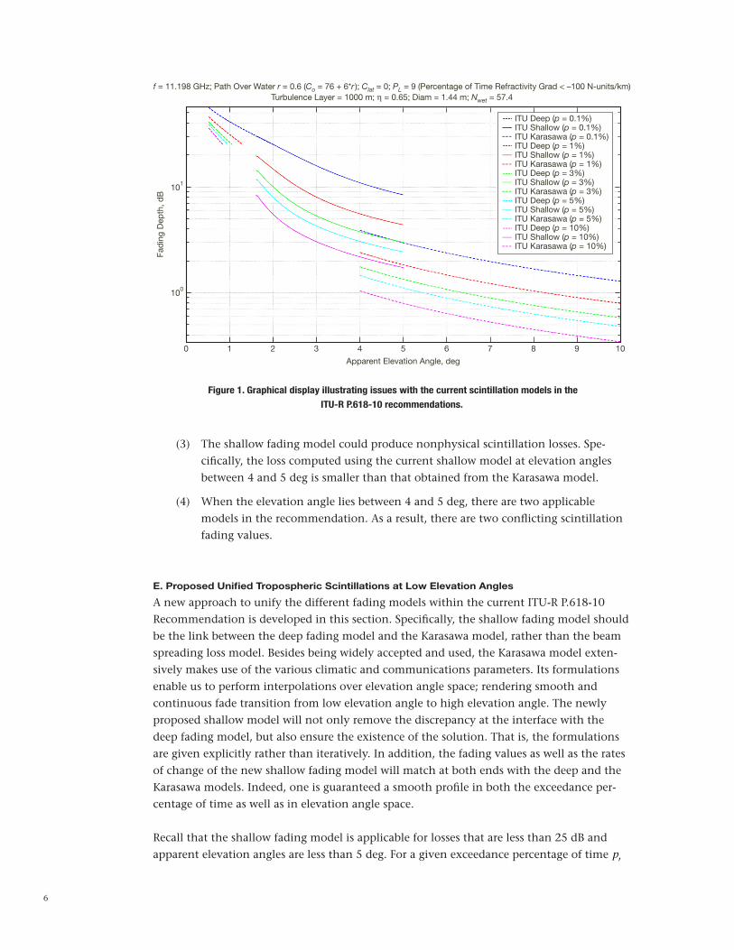
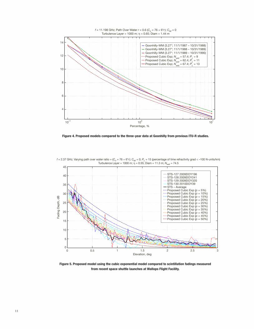
We next discuss the comparison of the proposed model with collected data. Although many studies have been carried out, very few have been focused on characterizing such effects on Earth–space links at very low elevation angles. At the present, we have obtained a data set from the ITU-R Study Group 3. With the appropriate permission, we were able to download Table II-6 from the ITU-R website [5], which included the fade values for Goonhilly, Great Britain. Figure 4 shows the worst-month scintillation fades at Goonhilly for three years (1987–1990) compared to those of the proposed model at a 3.27-deg elevation angle over various temporal exceedance percentages [6,7]. The fading depths of the proposed model are computed using Goonhilly’s antenna parameters and local geoclimatic parameters. The diameter of the receiving antenna is 1.44 m and the signal frequency is 11.198 GHz. Both the surface refractivity value Nwet and the meteorological factor PL for Goonhilly (Lat = 50 deg N, Lon = 5.2 deg W) were approximated graphically from the contour maps in Figure 3 and Figure 10 of the ITU-R P.453-9 Recommendation [3], respectively. Particularly,
Nwet = 57.4 and PL = 9 were assumed in the calculations. In addition, the satellite used in the experiments was the INTELSAT V F-7, a geostationary satellite located at 66 deg due east longitude (over the Indian Ocean). Based on the geographical location of the Goonhilly and the link path to the satellite, the percentage of the Earth–space path over water was as-sumed to be 60 percent. As shown in Figure 4, the fading depths from the proposed model using the Goonhilly parameters are a little lower than the worst-month measurements. Such a gap can be narrowed when the surface refractivity value Nwet and the meteorological factor PL are slightly increased.
B. NASA — Space Shuttle Launches
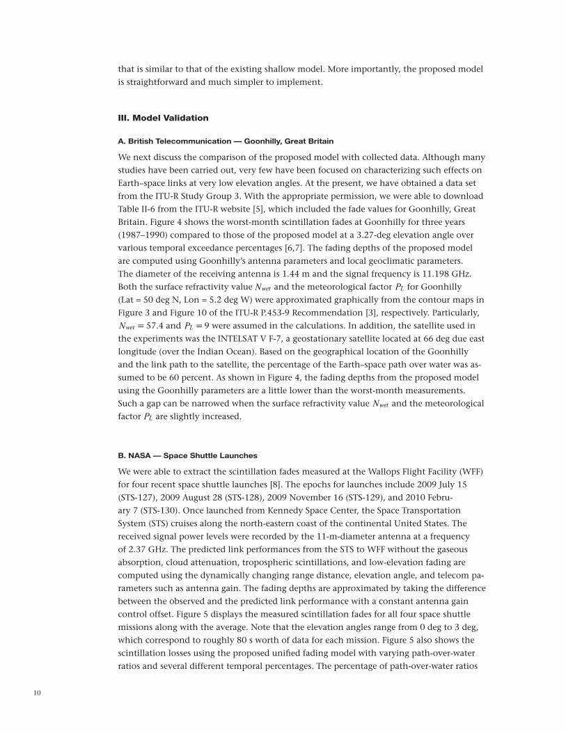
We were able to extract the scintillation fades measured at the Wallops Flight Facility (WFF) for four recent space shuttle launches [8]. The epochs for launches include 2009 July 15 (STS-127), 2009 August 28 (STS-128), 2009 November 16 (STS-129), and 2010 Febru-ary 7 (STS-130). Once launched from Kennedy Space Center, the Space Transportation System (STS) cruises along the north-eastern coast of the continental United States. The received signal power levels were recorded by the 11-m-diameter antenna at a frequency of 2.37 GHz. The predicted link performances from the STS to WFF without the gaseous absorption, cloud attenuation, tropospheric scintillations, and low-elevation fading are computed using the dynamically changing range distance, elevation angle, and telecom pa-rameters such as antenna gain. The fading depths are approximated by taking the difference between the observed and the predicted link performance with a constant antenna gain control offset. Figure 5 displays the measured scintillation fades for all four space shuttle missions along with the average. Note that the elevation angles range from 0 deg to 3 deg, which correspond to roughly 80 s worth of data for each mission. Figure 5 also shows the scintillation losses using the proposed unified fading model with varying path-over-water ratios and several different temporal percentages. The percentage of path-over-water ratios
11
Figure 4. Proposed models compared to the three-year data at Goonhilly from previous ITU-R studies.
Figure 5. Proposed model using the cubic exponential model compared to scintillation fadings measured
from recent space shuttle launches at Wallops Flight Facility.
Fad
ing
Dep
th, d
B
Elevation, deg
STS-127 2009DOY196STS-128 2009DOY241STS-129 2009DOY320STS-130 2010DOY39STS – AverageProposed Cubic Exp (p = 5%)Proposed Cubic Exp (p = 10%)Proposed Cubic Exp (p = 15%)Proposed Cubic Exp (p = 20%)Proposed Cubic Exp (p = 25%)Proposed Cubic Exp (p = 30%)Proposed Cubic Exp (p = 35%)Proposed Cubic Exp (p = 40%)Proposed Cubic Exp (p = 45%)Proposed Cubic Exp (p = 50%)
f = 2.37 GHz; Varying path over water ratio = (Co = 76 + 6*r ); Clat = 0; PL = 15 (percentage of time refractivity grad < –100 N-units/km)Turbulence Layer = 1000 m; h = 0.55; Diam = 11.3 m; Nwet = 74.5
45
40
35
0 0.5 1 1.5 2 2.5 3
30
25
20
15
10
5
0
10–1 100 101
Percentage, %
f = 11.198 GHz; Path Over Water r = 0.6 (Co = 76 + 6*r ); Clat = 0Turbulence Layer = 1000 m; h = 0.65; Diam = 1.44 m
14
12
10
8
6
4
Goonhilly-WM (3.27°; 11/1/1987 – 10/31/1988)Goonhilly-WM (3.27°; 11/1/1988 – 10/31/1989)Goonhilly-WM (3.27°; 11/1/1989 – 10/31/1990)Proposed Cubic Exp; N
wet = 57.4; P
L = 9
Proposed Cubic Exp; Nwet
= 62.4; PL = 11
Proposed Cubic Exp; Nwet
= 67.4; PL = 13

12
from STS to WFF are computed from the geological location of the trajectory path of the STS and vary from 67 percent (0 deg elevation) to 71 percent (3 deg elevation). Similar to Goonhilly, both the surface refractivity value Nwet and the meteorological factor PL for Wal-lops were approximated graphically from the ITU-R P.453-9 Recommendation [3]. Particu-larly, Nwet = 74.5 and PL = 15 were assumed in the calculations. Overall, the scintillation fades for both scenarios agree well with those predicted by the proposed model.
IV. Summary
A new unified method for fading prediction at low elevation angles was proposed. The cur-rent ITU-R P.618-10 Recommendation suggests a shallow fading model that interpolates the deep fading model and the beam spreading model over the exceedance percentage space. Several issues associated with the current ITU Recommendation have been found. Particu-larly, the solution to this shallow model is determined iteratively, and, in many instances, does not converge, especially near the deep fading interface. In addition, because the beam spreading loss model (depending solely on the elevation angle) is quite simplistic, predic-tions from the ITU shallow fading model are independent of climatic and communications parameters. Therefore, its predictions produce unrealistic nonphysical values; for example, the losses, produced using the existing shallow model at elevations angles lower than 4 deg, are smaller than those computed using the Karasawa model under severe weather and geo-climatic conditions. Moreover, as the elevation angle increases, the scintillation prediction profile using the current ITU Recommendation contradicts that of the Karasawa model and results in a discontinuity in scintillation values. In the proposed model, the shallow fad-ing model is constructed by unifying the deep fade model for low elevation angles and the Karasawa scintillation model for elevation angles of 5 deg and higher. The resulting model is a cubic exponential function of elevation angle, whose coefficients are derived from the values and their derivatives of the deep fading and the Karasawa models at the interfaces. The solution to the unified model is found directly (not iteratively) and its profile is smooth in both exceedance percentage and elevation angle. Since the Karasawa model includes dependence with meteorological parameters along with ground station antenna parameters (which have not been taken into account in the existing beam spreading loss model), the scintillation fading predicted from the proposed shallow fading model is expected to more closely agree with that obtained from measured signal level data. Tropospheric scintillations measured from Goonhilly, Great Britain, and NASA’s space shuttle launches have been pre-sented and shown to agree well with those predicted from this newly proposed model.
Acknowledgments
The authors would like to thank the ITU-R US Study Group 3 (Radiowave Propagation), especially Harvey Berger, Fatim Haidara, and Paul McKenna for supporting numerous group meetings and the suggestions, correction, and completion of the ITU Annexes. The authors also appreciate the feedback from David D. Morabito and Selahattin Kayalar at JPL and the shuttle data from Rob Tye and Ed Richards at NASA WFF.

13
References
[1] ITU-R, “Propagation Data and Prediction Methods Required for the Design of Earth–Space Telecommunications Systems,” Rec. ITU-R P.618-10, 2009.
[2] Y. Karasawa, M. Yamada, and J. E. Allnutt, “A New Prediction Method for Tropospheric Scintillation on Earth–Space Paths,” IEEE Transactions on Antennas and Propagation, vol. 36, pp. 1608–1614, 1988.
[3] ITU-R, “The Radio Refractive Index: Its Formula and Refractivity Data,” Rec. ITU-R P.453-9, 2003.
[4] ITU-R, “Effects of Tropospheric Refraction on Radiowave Propagation,” Rec. ITU-R P.834-3, 1999.
[5] ITU-R Website, Study Group 3 databanks — DBSG3 — Table III-1a and VHF/UHF. http://www.itu.int/ITU-R
[6] E. C. Johnston, D. L. Bryant, D. Maiti, and J. E. Allnutt, “Results of Low Elevation Angle 11 GHz Satellite Beacon Measurements at Goonhilly,” 7th International Conference on Antennas and Propagation, vol. 1, pp. 366–369, 1991.
[7] M. M. B. Mohd Yusoff, N. Sengupta, C. Alder, I. A. Glover, P. A. Watson, R. G. Howell, and D. L. Bryant, “Evidence for the Presence of Turbulent Attenuation on Low-Eleva-tion Angle Earth–Space paths, Part I: Comparison of CCIR Recommendation and Scin-tillation Observations on a 3.3° Path,” IEEE Transactions on Antennas and Propagation, vol. 45, pp. 73–84, 1997.
[8] K. Cheung, C. Ho, A. Kantak, C. H. Lee, R. Tye, E. Richards, C. Sham, A. Schlesinger, and B. Barritt, “Wallops’ Low Elevation Link Analysis for the Constellation Launch/ Ascent Links,” 2011 IEEE Aerospace Conference, Big Sky, Montana, March 5–12, 2011.