Embed Size (px)
Citation preview

A Time-Centric Model for Cyber-Physical Applications
John C. Eidson, Edward A. Lee, Slobodan Matic, Sanjit A. Seshia, and Jia Zou
University of California at Berkeley, Berkeley, CA, 94720, USA{eidson,eal,matic,sseshia,jiazou}@eecs.berkeley.edu
Abstract. The problem addressed by this paper is that real-time embedded soft-ware today is commonly built using programming abstractions with little or notemporal semantics. The paper discusses the use of an extension to the PtolemyII framework as a coordination language for the design of distributed real-timeembedded systems. Specifically, the paper shows how to use modal models in thecontext of the PTIDES extension of Ptolemy II to provide a firm basis for thedesign of an important class of problems. We show the use of this environment inthe design of interesting practical real-time systems.
1 IntroductionIn cyber-physical systems (CPS) the passage of time becomes a central feature — infact, it is this key constraint that distinguishes these systems from distributed comput-ing in general. Time is central to predicting, measuring, and controlling properties ofthe physical world: given a physical model, the initial state, the inputs, and the amountof time elapsed, one can compute the current state of the plant. This principle pro-vides the foundations of control theory. However, for current mainstream programmingparadigms, given the source code, the program’s initial state, and the amount of timeelapsed, we cannot reliably predict future program state. When that program is inte-grated into a system with physical dynamics, this makes principled design of the entiresystem difficult. Moreover, the disparity between the dynamics of the physical plant andthe program potentially leads to errors, some of which can be catastrophic.
The challenge of integrating computing and physical processes has been recognizedfor some time, motivating the emergence of hybrid systems theories. Progress in thatarea, however, remains limited to relatively simple systems combining ordinary differ-ential equations with automata. These models inherit from control theory a uniform no-tion of time, an oracle called t available simultaneously in all parts of the system. Evenadaptations of traditional computer science concepts to distributed control problemsmake the assumption of the oracle t. For example, in [21] consensus problems fromcomputer science are translated into control systems formulations. These formulations,however, break down without the uniform notion of time that governs the dynamics. Innetworked software implementations, such a uniform notion of time cannot be preciselyrealized. Time triggered networks [12] can be used to approximate a uniform model oftime, but the analysis of the dynamics has to include the imperfections.
Although real-time software is not a new problem there exist trends with a potentialto change the landscape. Model-based design [11], for example, has caught on in in-dustrial practice, through the use of tools such as Simulink, TargetLink, and LabVIEW.Domain-specific modeling languages are increasingly being used because they tend tohave formal semantics that experts can use to describe their domain constraints. This
MoDELS 2010 ACES-MB Workshop Proceedings
Oslo, Norway, October 4, 2010 21
enables safety or quality of service verification, and thus helps with integration andscalability of designed systems. For CPS, models with temporal semantics are particu-larly natural to system designers. An example of such a language is Timing-AugmentedDescription Language [10], a domain-specific language recently developed within theautomotive initiative AUTOSAR. However, the multiplication of modeling languagesraises the question of mutual consistency and interoperability. This is mainly why theOMG consortium extended UML with a profile called MARTE (Modeling and Anal-ysis of Real-Time and Embedded Systems) [23]. Another trend is the acceptance ofsynchronous-reactive languages, particularly SCADE [1], in safety critical applications.The model-based design approach we propose in this paper borrows sound fixed-pointsemantics from the synchronous languages, but is more flexible and concurrent. Alsorelated to our work are component frameworks based on formal verification methods,like the BIP framework [2], but they mostly focus on compositional verification of prop-erties such as deadlock freedom. BIP relies on priorities to model scheduling policiesand, as far as we know, has not been used to address modeling and design problems forcomponents with explicit timing requirements.
To ensure proper real-time interaction between the dynamics of the controller andthe dynamics of the controlled physical system, programmers of embedded systemstypically use platform-specific system timers. However, design of the system should beindependent of implementation details, in order to allow for portability of the design.In [26] we presented a programming model called PTIDES (programming temporally-
integrated distributed embedded systems) that addresses this problem by relying on asuitable abstraction of time. With PTIDES, application programmers specify the inter-action between the control program and the physical dynamics in the system model,without the knowledge of details such as timers. Paper [28] studies the semantic prop-erties of an execution model that permits out of order processing of events withoutsacrificing determinacy and without requiring backtracking.
The goal of this work is to demonstrate the usefulness of PTIDES for time-criticalCPS applications. We first explain how design with PTIDES results in deterministicprocessing of events. Then we illustrate how to specify timed reactions to events inPTIDES models. This results in traces from model simulation and execution of auto-matically generated code being identical. In order to account for different modes ofoperation, modal models have been widely used in embedded system design [8]. Here,we show the use of modal models within the context of a timed environment, i.e., weillustrate timed mode transitions and operations in modes at certain time instants.
This paper is organized as follows. First, section 2 discusses the PTIDES designenvironment, which enables a programmer to first model and simulate the design, andthen implement it through a target-specific code generator. At the top level, this envi-ronment uses the PTIDES [26] extension to the Ptolemy II simulation framework [7] asa coordination language for the design of distributed real-time embedded systems. Sec-tion 3 then explains temporal semantics of PTIDES, and shows how the use of modalmodels in the context of PTIDES provides a firm basis for the design of an importantclass of CPS. This is followed by a detailed example in section 4, which shows the useof this environment and particularly the ability to explicitly address timing in the designof interesting practical real-time systems. We conclude in section 5.
MoDELS 2010 ACES-MB Workshop Proceedings
Oslo, Norway, October 4, 2010 22
2 Design Environment
2.1 PTIDES Workflow
PTIDES�Simulator
Design
SimulationSchedulability
Analysis
Code P
Analysis
Code�Generation
Program�Analysis
PtidyOSRuntime
PtidyOS
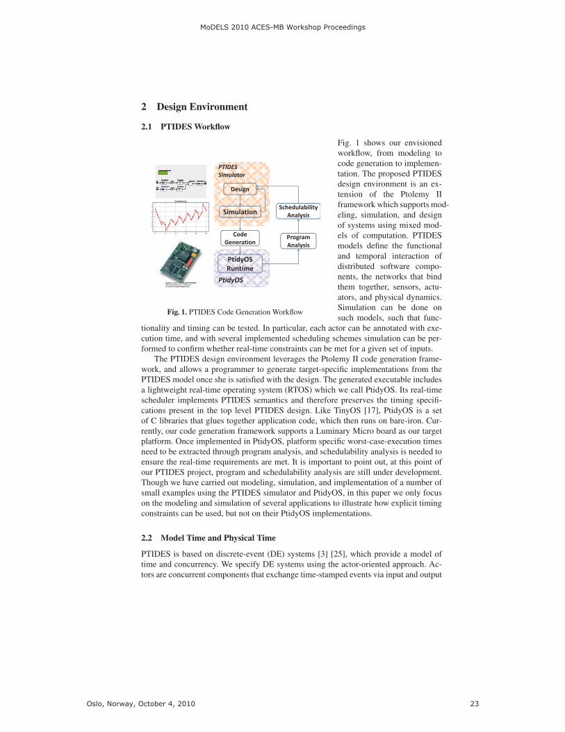
Fig. 1. PTIDES Code Generation Workflow
Fig. 1 shows our envisionedworkflow, from modeling tocode generation to implemen-tation. The proposed PTIDESdesign environment is an ex-tension of the Ptolemy IIframework which supports mod-eling, simulation, and designof systems using mixed mod-els of computation. PTIDESmodels define the functionaland temporal interaction ofdistributed software compo-nents, the networks that bindthem together, sensors, actu-ators, and physical dynamics.Simulation can be done onsuch models, such that func-
tionality and timing can be tested. In particular, each actor can be annotated with exe-cution time, and with several implemented scheduling schemes simulation can be per-formed to confirm whether real-time constraints can be met for a given set of inputs.
The PTIDES design environment leverages the Ptolemy II code generation frame-work, and allows a programmer to generate target-specific implementations from thePTIDES model once she is satisfied with the design. The generated executable includesa lightweight real-time operating system (RTOS) which we call PtidyOS. Its real-timescheduler implements PTIDES semantics and therefore preserves the timing specifi-cations present in the top level PTIDES design. Like TinyOS [17], PtidyOS is a setof C libraries that glues together application code, which then runs on bare-iron. Cur-rently, our code generation framework supports a Luminary Micro board as our targetplatform. Once implemented in PtidyOS, platform specific worst-case-execution timesneed to be extracted through program analysis, and schedulability analysis is needed toensure the real-time requirements are met. It is important to point out, at this point ofour PTIDES project, program and schedulability analysis are still under development.Though we have carried out modeling, simulation, and implementation of a number ofsmall examples using the PTIDES simulator and PtidyOS, in this paper we only focuson the modeling and simulation of several applications to illustrate how explicit timingconstraints can be used, but not on their PtidyOS implementations.
2.2 Model Time and Physical Time
PTIDES is based on discrete-event (DE) systems [3] [25], which provide a model oftime and concurrency. We specify DE systems using the actor-oriented approach. Ac-tors are concurrent components that exchange time-stamped events via input and output
MoDELS 2010 ACES-MB Workshop Proceedings
Oslo, Norway, October 4, 2010 23
ports. The time in time stamps is a part of the model, playing a formal role in the com-putation. We refer to this time as model time. It may or may not bear any relationshipto time in the physical world, which in this paper we will call physical time. In basicDE semantics, each actor processes input events in time-stamp order. There are no con-straints on the physical time at which events are processed. We assume a variant of DEthat has been shown to integrate well with models of continuous dynamics [16]. Thepurpose of this paper is not to study its rigorous and determinate semantics. For that aninterested reader is referred to [18] and [13].
PTIDES extends DE by establishing a relationship between model time and physi-cal time at sensors, actuators, and network interfaces. Whereas DE models have tradi-tionally been used to construct simulations, PTIDES provides a programmer’s modelfor the specification of both functional and temporal properties of deployable cyber-physical systems. There are three key constraints that define the relationship betweenmodel time and physical time: 1) sensors produce events with timetamp τ at physicaltime t ≥ τ , 2) actuators receives events with timestamp τ at physical time t ≤ τ , and 3)network interfaces receive events with timestamp τ at physical time t ≤ τ . We explainthese constraints in detail below.
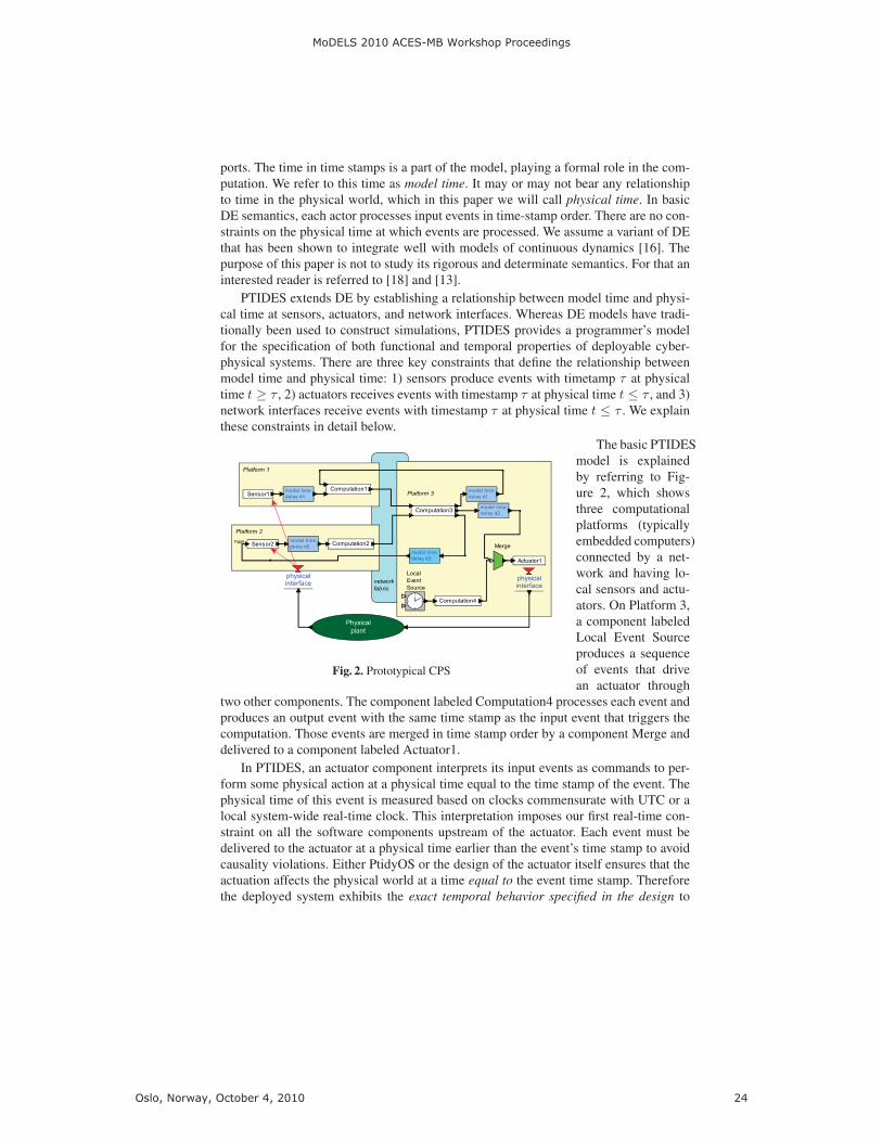
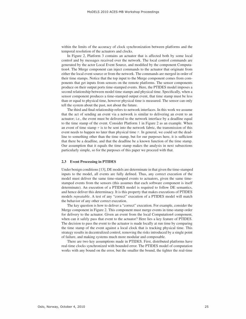
Fig. 2. Prototypical CPS
The basic PTIDESmodel is explainedby referring to Fig-ure 2, which showsthree computationalplatforms (typicallyembedded computers)connected by a net-work and having lo-cal sensors and actu-ators. On Platform 3,a component labeledLocal Event Sourceproduces a sequenceof events that drivean actuator through
two other components. The component labeled Computation4 processes each event andproduces an output event with the same time stamp as the input event that triggers thecomputation. Those events are merged in time stamp order by a component Merge anddelivered to a component labeled Actuator1.
In PTIDES, an actuator component interprets its input events as commands to per-form some physical action at a physical time equal to the time stamp of the event. Thephysical time of this event is measured based on clocks commensurate with UTC or alocal system-wide real-time clock. This interpretation imposes our first real-time con-straint on all the software components upstream of the actuator. Each event must bedelivered to the actuator at a physical time earlier than the event’s time stamp to avoidcausality violations. Either PtidyOS or the design of the actuator itself ensures that theactuation affects the physical world at a time equal to the event time stamp. Thereforethe deployed system exhibits the exact temporal behavior specified in the design to
MoDELS 2010 ACES-MB Workshop Proceedings
Oslo, Norway, October 4, 2010 24
within the limits of the accuracy of clock synchronization between platforms and thetemporal resolution of the actuators and clocks.
In Figure 2, Platform 3 contains an actuator that is affected both by some localcontrol and by messages received over the network. The local control commands aregenerated by the actor Local Event Source, and modified by the component Computa-tion4. The Merge component can inject commands to the actuator that originate fromeither the local event source or from the network. The commands are merged in order oftheir time stamps. Notice that the top input to the Merge component comes from com-ponents that get inputs from sensors on the remote platforms. The sensor componentsproduce on their output ports time-stamped events. Here, the PTIDES model imposes asecond relationship between model time stamps and physical time. Specifically, when asensor component produces a time-stamped output event, that time stamp must be lessthan or equal to physical time, however physical time is measured. The sensor can onlytell the system about the past, not about the future.
The third and final relationship refers to network interfaces. In this work we assumethat the act of sending an event via a network is similar to delivering an event to anactuator; i.e., the event must be delivered to the network interface by a deadline equalto the time stamp of the event. Consider Platform 1 in Figure 2 as an example. Whenan event of time stamp τ is to be sent into the network fabric, the transmission of thisevent needs to happen no later than physical time τ . In general, we could set the dead-line to something other than the time stamp, but for our purposes here, it is sufficientthat there be a deadline, and that the deadline be a known function of the time stamp.Our assumption that it equals the time stamp makes the analysis in next subsectionsparticularly simple, so for the purposes of this paper we proceed with that.
2.3 Event Processing in PTIDES
Under benign conditions [13], DE models are determinate in that given the time-stampedinputs to the model, all events are fully defined. Thus, any correct execution of themodel must deliver the same time-stamped events to actuators, given the same time-stamped events from the sensors (this assumes that each software component is itselfdeterminate). An execution of a PTIDES model is required to follow DE semantics,and hence deliver this determinacy. It is this property that makes executions of PTIDESmodels repeatable. A test of any “correct” execution of a PTIDES model will matchthe behavior of any other correct execution.
The key question is how to deliver a “correct” execution. For example, consider theMerge component in Figure 2. This component must merge events in time-stamp orderfor delivery to the actuator. Given an event from the local Computation4 component,when can it safely pass that event to the actuator? Here lies a key feature of PTIDES.The decision to pass the event to the actuator is made locally at run time by comparingthe time stamp of the event against a local clock that is tracking physical time. Thisstrategy results in decentralized control, removing the risks introduced by a single pointof failure, and making systems much more modular and composable.
There are two key assumptions made in PTIDES. First, distributed platforms havereal-time clocks synchronized with bounded error. The PTIDES model of computationworks with any bound on the error, but the smaller the bound, the tighter the real-time
MoDELS 2010 ACES-MB Workshop Proceedings
Oslo, Norway, October 4, 2010 25
constraints can be. Time synchronization techniques such as IEEE 1588 [9] can deliverreal-time clock precision on the nanosecond order.
Second, PTIDES requires that there be a bound on the communication delay be-tween any two hardware components. Specifically, sensors and actuators must delivertime-stamped events to the run-time system within a bounded delay, and a networkmust transport a time-stamped event with a bounded delay. Bounding network delayis potentially more problematic when using generic networking technologies such asEthernet, but bounded network delay is already required today in the applications of in-terest here. This has in fact historically forced deployments of these applications to usespecialized networking techniques (such as time-triggered architectures [12], FlexRay[19], and CAN buses [24]). One of the goals of our research is to use PTIDES on lessconstraining networking architectures, e.g. to allow more flexibility in processing aperi-odic events. In the time-triggered architectures, all actions are initiated by the computersystem at known time instants. In our approach, events coming from the environmentare allowed and are treated deterministically. Here it is sufficient to observe that theseboundedness assumptions are achievable in practice. Since PTIDES allows detection ofrun-time timing errors, it is possible to model responses to failures of these assumptions.
Once these two assumptions (bounded time synchronization error and communica-tion delays) are accepted, together with deadlines for network interfaces and actuators,local decisions can be made to deliver events in Figure 2 without compromising DEsemantics. Specifically, in Figure 2, notice that the top input to the Merge comes fromSensor1 and Sensor2 through a chain of software components and a network link. Staticanalysis of these chains reveals the operations performed on time stamps. In particular,in this figure, assume that the only components that manipulate time stamps are thecomponents labeled model time delay di. These components accept an input event andproduce an output event with the same data but with a time stamp incremented by di.
Assume we have an event e with time stamp τ at the bottom input of Merge, and thatthere is no other event on Platform 3 with an earlier time stamp. This event can be passedto the output only when we are sure that no event will later appear at the top input ofMerge with a time stamp less than or equal to τ . This will preserve DE semantics. Whencan we be sure that e is safe to process in this way? We assume that events destined tothe top input of Merge must be produced by a reaction in Computation3 to events thatarrive over the network. Moreover, the outputs of Computation3 are further processedto increment their time stamps by d2. Thus, we are sure e is safe to process when noevents from the network will arrive at Platform 3 with time stamps less than or equal toτ − d2. When can we be sure of this? Let us assume a network delay bound of n anda clock synchronization error bound of s between platforms. By the network interfaceassumption discussed above, we know that all events sent by Platform 1 or Platform 2with time stamps less than τ − d2 will be sent over the network by the physical timeτ − d2. Consequently, all events with time stamp less than or equal to τ − d2 will bereceived on Platform3 by the physical time τ − d2 + n+ s, where the s term accountsfor the possible disagreement in the measurement of physical time. Thus when physicaltime on Platform 3 exceeds τ−d2+n+s, event e will be safe to process. In other words,to ensure that the processing of an event obeys DE semantics, at run time, the only testthat is needed is to compare time stamps to physical time with an offset (in the previousexample, the offset is−d2+n+s). Notice, if we assume the model is static (components
MoDELS 2010 ACES-MB Workshop Proceedings
Oslo, Norway, October 4, 2010 26
are not added during runtime and connections are not changed); minimum bounds onmodel time delays (di’s) for components are known statically; and the upper boundsfor sensor processing times, network delays, and network synchronization errors areknown, then the offsets can be calculated statically using a graph traversal algorithm.
Note that the distributed execution control of PTIDES introduces another valuableform of robustness in the system. For example, in Figure 2, if, say, Platform 1 ceasesfunctioning altogether, and stops sending events on the network, that fact alone cannotprevent Platform 3 from continuing to drive its actuator with locally generated controlsignals. This would not be true if we preserved DE semantics by conservative tech-niques based on the work by Chandy and Misra [4]. It is also easy to see that PTIDESmodels can include components that monitor system integrity. For example, Platform3 could raise an alarm and change operating modes if it fails to get messages fromPlatform 1. It could also raise an alarm if it later receives a message with an unexpect-edly small time stamp. Time synchronization with bounded error helps to give suchmechanisms a rigorous semantics.
As long as events are delivered on time and in time-stamp order to actuators, theexecution will look exactly the same to the environment. This makes PTIDES modelsmuch more robust than typical real-time software, because small changes in the (phys-ical) execution timing of internal events are not visible to the environment (as long asreal-time constraints are met at sensors, actuators and network interfaces). Moreover,since execution of a PTIDES model carries time stamps at run time, run time violationsof deadlines at actuators can be detected. PTIDES models can be easily made adaptive,changing modes of operation, for example, when such real-time violations occur. Ingeneral, therefore, PTIDES models provide adequate runtime information for detectingand reacting to a rich variety of timing faults.
3 Temporal Semantics in PTIDES
PTIDES semantics is fully described in [26] and [28], and is based on a tagged-signalmodel [15]. For this discussion the important point is that actors define a functionalrelationship between a set of tagged signals on the input ports and a set of tagged signalson the output ports of the actor, Fa : SI → SO. Here, I is a set of input ports, O is aset of output ports, and S a set of signals. The signals s ∈ S are sets of (time stamp,value) pairs of the form (τ, v) ∈ T ×V where the time set T represents time and V is aset of values (the data payloads) of events. For simulation, the most common use of DEmodeling, time stamps typically have no connection with real time, and can advanceslower or faster than real time [25].
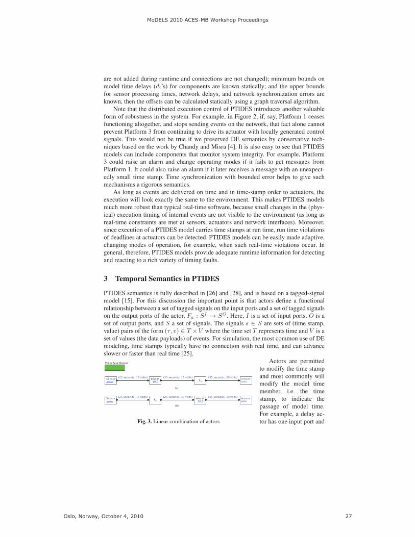
Fig. 3. Linear combination of actors
Actors are permittedto modify the time stampand most commonly willmodify the model timemember, i.e. the timestamp, to indicate thepassage of model time.For example, a delay ac-tor has one input port and
MoDELS 2010 ACES-MB Workshop Proceedings
Oslo, Norway, October 4, 2010 27
one output port and its behavior is given by Fδ(s) : S → S where for each s ∈ S wehave Fδ(s) = {(t+ δ, v) | (t, v) ∈ s}. That is, the output events are identical to inputevents except that the model time is increased by δ, a parameter of the actor.
Consider the simple sensor, actor, actuator system of Figure 3. In this example weassume Fa(s) = {(t, 2 ∗ v) | (t, v) ∈ s}; i.e., the output is the same as the input but withits value scaled by a factor of 2. Both variants (a) and (b) of this figure show a serialcombination of a sensor, delay, scaling, and actuator actors. The sensor actors producean event (25 seconds, 15 volts) where the time stamp 25 seconds is the physical timeat the time of sensing. The delay actor increments the model time by 10 and the scaleactor doubles the value from 15 volts to 30 volts. In both cases the actuator receivesan event (35 seconds, 30 volts), which it interprets as a command to the actuator toinstantiate the value 30 volts at a physical time of 35 seconds. As long as deadlinesat the actuators are met, all observable effects with models (a) and (b) are identical,regardless of computation times and scheduling decisions.
Modal Models.
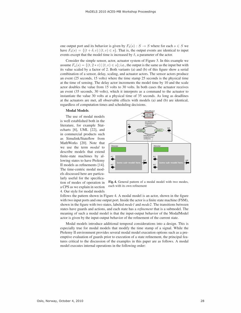
Fig. 4. General pattern of a modal model with two modes,each with its own refinement
The use of modal modelsis well established both in theliterature, for example Stat-echarts [8], UML [22], andin commercial products suchas Simulink/Stateflow fromMathWorks [20]. Note thatwe use the term modal todescribe models that extendfinite-state machines by al-lowing states to have PtolemyII models as refinements [14].The time-centric modal mod-els discussed here are particu-larly useful for the specifica-tion of modes of operation ina CPS as we explain in section4. Our style for modal modelsfollows the pattern shown in Figure 4. A modal model is an actor, shown in the figurewith two input ports and one output port. Inside the actor is a finite state machine (FSM),shown in the figure with two states, labeled mode1 and mode2. The transitions betweenstates have guards and actions, and each state has a refinement that is a submodel. Themeaning of such a modal model is that the input-output behavior of the ModalModelactor is given by the input-output behavior of the refinement of the current state.
Modal models introduce additional temporal considerations into a design. This isespecially true for modal models that modify the time stamp of a signal. While thePtolemy II environment provides several modal model execution options such as a pre-emptive evaluation of guards prior to execution of a state refinement, the principal fea-tures critical to the discussion of the examples in this paper are as follows. A modalmodel executes internal operations in the following order:
MoDELS 2010 ACES-MB Workshop Proceedings
Oslo, Norway, October 4, 2010 28
– When the modal model reacts to a set of input events with time stamp τ , it firstpresents those input events to the refinement of the current state i. That refinementmay, in reaction, produce output events with time stamp τ .
– If any of input events have an effect within the refinement at a later time stampτ ′ > τ , that effect is postponed. The modal model is invoked again at time stampτ ′, and only if the current state is still i will the effect be instantiated.
– The guards of all transitions originating from the current state are evaluated basedon the current inputs, state variables, and outputs of the current state refinementwith the same time stamp τ as the current inputs.
– If one of the guards evaluates to true, the transition and any associated actionsare executed, and the new current state i′ becomes that at the destination of thetransition.
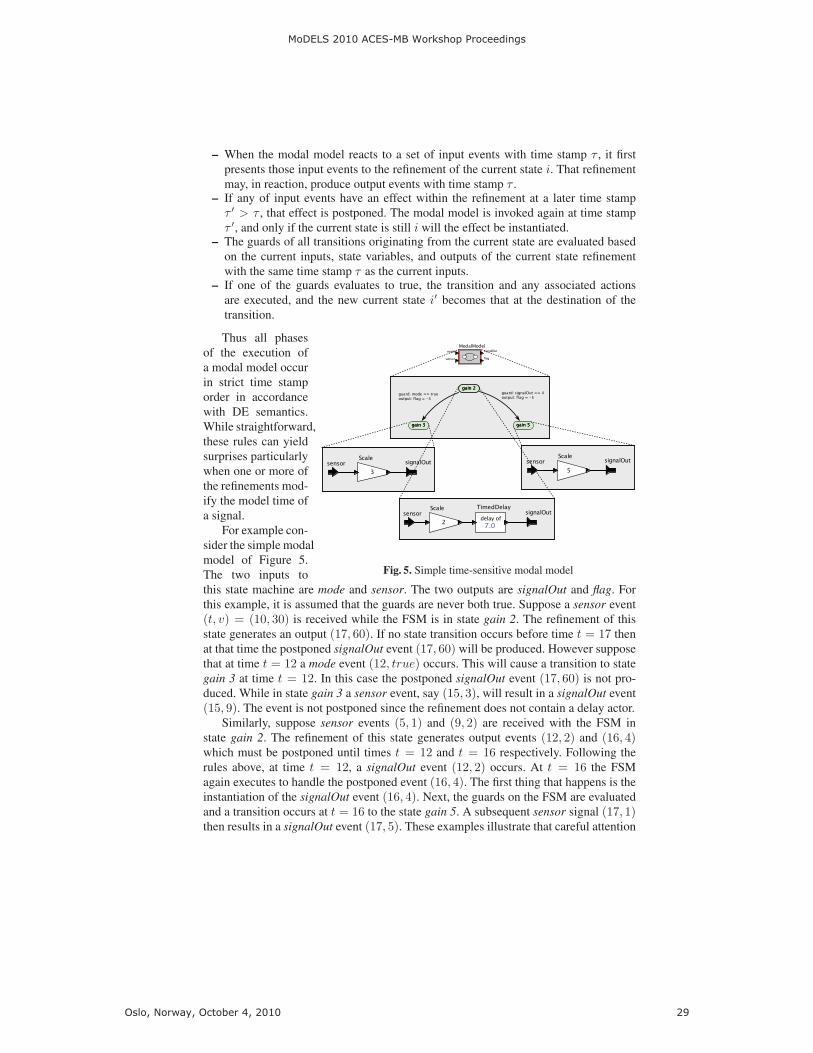
Fig. 5. Simple time-sensitive modal model
Thus all phasesof the execution ofa modal model occurin strict time stamporder in accordancewith DE semantics.While straightforward,these rules can yieldsurprises particularlywhen one or more ofthe refinements mod-ify the model time ofa signal.
For example con-sider the simple modalmodel of Figure 5.The two inputs tothis state machine are mode and sensor. The two outputs are signalOut and flag. Forthis example, it is assumed that the guards are never both true. Suppose a sensor event(t, v) = (10, 30) is received while the FSM is in state gain 2. The refinement of thisstate generates an output (17, 60). If no state transition occurs before time t = 17 thenat that time the postponed signalOut event (17, 60) will be produced. However supposethat at time t = 12 a mode event (12, true) occurs. This will cause a transition to stategain 3 at time t = 12. In this case the postponed signalOut event (17, 60) is not pro-duced. While in state gain 3 a sensor event, say (15, 3), will result in a signalOut event(15, 9). The event is not postponed since the refinement does not contain a delay actor.
Similarly, suppose sensor events (5, 1) and (9, 2) are received with the FSM instate gain 2. The refinement of this state generates output events (12, 2) and (16, 4)which must be postponed until times t = 12 and t = 16 respectively. Following therules above, at time t = 12, a signalOut event (12, 2) occurs. At t = 16 the FSMagain executes to handle the postponed event (16, 4). The first thing that happens is theinstantiation of the signalOut event (16, 4). Next, the guards on the FSM are evaluatedand a transition occurs at t = 16 to the state gain 5. A subsequent sensor signal (17, 1)then results in a signalOut event (17, 5). These examples illustrate that careful attention
MoDELS 2010 ACES-MB Workshop Proceedings
Oslo, Norway, October 4, 2010 29

must be paid to the temporal semantics of the modal models to ensure that the desiredapplication behavior results.
4 Application Study
PTIDES can be used to integrate models of software, networks, and physical plants.This is achieved by adopting the fixed-point semantics that makes it possible to mixcontinuous and discrete-event models [16]. A practical consequence is to enable CPSco-design and co-simulation. It also facilitates hardware in the loop (HIL) simulation,where deployable software can be tested (at greatly reduced cost and risk) against sim-ulations of the physical plant. The DE semantics of the model ensures that simulationswill match implementations, even if the simulation of the plant cannot execute in realtime. Conversely, prototypes of the software on generic execution platforms can betested against the actual physical plant. The model can be tested even if the softwarecontrollers are not fully implemented. This (extremely valuable) property cannot beachieved today because the temporal properties of the software emerge from an im-plementation, and therefore complete tests of the dynamics often cannot be performeduntil the final stages of system integration, with the actual physical plant, using the finalplatform.
The inclusion of a network into an embedded system introduces three principalcomplications in the design of embedded systems:
– To preserve DE semantics and the resulting determinism system wide, it is neces-sary to provide a common sense of time to all platforms. As noted in section 2 thisis often based on a time-slotted network protocol but can also be based on a clocksynchronization protocol such as IEEE 1588 [9].
– The design of model delays must now account not only for execution time within anactuation platform, e.g. the platform containing an actuator causally dependent onsignals from other platforms, but must include network delay as well as executiontime in platforms providing signals via the network to the actuation platform.
– To ensure bounded network delay it is usually necessary to enforce some sort ofadmission control explicitly controlling the time that traffic is introduced onto thenetwork.
The introduction of timed reactions further complicates the design and analysis ofsystem temporal semantics, particularly when these reactions must be synchronizedacross a multi-platform system. PTIDES is well suited in managing these multi-platformdesign issues. The remainder of this section illustrates the following features of thePTIDES design environment:
– The use of time-based detection of missing signals to drive mode changes in theoperation of power plants.
– The use of time-based models of the plant in testing controller implementations ofpower plants.
– The use of a modal model to specify the temporal behavior of the operational modesof a device.
MoDELS 2010 ACES-MB Workshop Proceedings
Oslo, Norway, October 4, 2010 30
– The use of synchronized clocks in a multi-platform system to allow FSMs and otheractors in each platform to enforce system-wide temporal behavior.
– The enforcement of correspondence between model and physical time at sensorsand actuators to ensure that such timing specifications are realized
– The enforcement at platform network outputs of sending deadlines to ensure thatmulti-platform feasible solutions are computable.
Power Plant Control.
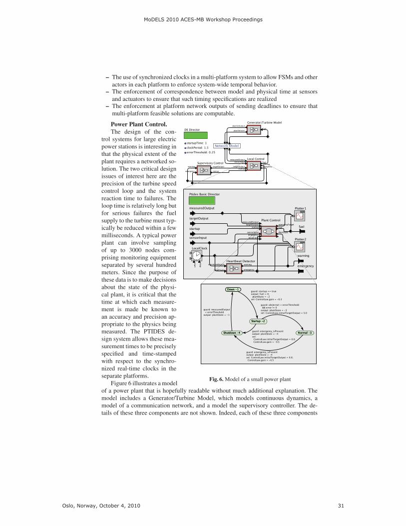
Fig. 6. Model of a small power plant
The design of the con-trol systems for large electricpower stations is interesting inthat the physical extent of theplant requires a networked so-lution. The two critical designissues of interest here are theprecision of the turbine speedcontrol loop and the systemreaction time to failures. Theloop time is relatively long butfor serious failures the fuelsupply to the turbine must typ-ically be reduced within a fewmilliseconds. A typical powerplant can involve samplingof up to 3000 nodes com-prising monitoring equipmentseparated by several hundredmeters. Since the purpose ofthese data is to make decisionsabout the state of the physi-cal plant, it is critical that thetime at which each measure-ment is made be known toan accuracy and precision ap-propriate to the physics beingmeasured. The PTIDES de-sign system allows these mea-surement times to be preciselyspecified and time-stampedwith respect to the synchro-nized real-time clocks in theseparate platforms.
Figure 6 illustrates a modelof a power plant that is hopefully readable without much additional explanation. Themodel includes a Generator/Turbine Model, which models continuous dynamics, amodel of a communication network, and a model the supervisory controller. The de-tails of these three components are not shown. Indeed, each of these three components
MoDELS 2010 ACES-MB Workshop Proceedings
Oslo, Norway, October 4, 2010 31

can be quite sophisticated models, although for our purposes here will use rather sim-ple versions. The model in Figure 6 also includes a local controller, which is expandedshowing two main components, a Heartbeat Detector and Plant Control block. A powerplant, like many CPS, can be characterized by several modes of operation each of whichcan have different time semantics. This is reflected in the design of the Plant Controlblock that is implemented with a four state modal model based on the discussion ofsection 3 . The Down state represents the off state of the power plant. Upon receipt of a(time-stamped) startup event from the supervisory controller, this modal model transi-tions to the Startup state. When the measured discrepancy between electric power outputand the target output gets below a threshold given by errorThreshold, the modal modeltransitions to the Normal state. If it receives a (time-stamped) emergency event fromthe Heartbeat Detector, then it will transition to the Shutdown state, and after achievingshutdown, to the Down state. Each of these states has a refinement (not shown) that usesinput sensor data to specify the amount of fuel to supply to the generator/turbine. Thefuel amount is sent over the network to the actuators on the generator/turbine. Becauseboth the controller sensor input data and the resulting fuel control signal sent to theactuators are time stamped, the designer is able to use PTIDES construct to preciselyspecify the delay between sensors and actuators. Furthermore as described earlier exe-cutable code generated from the PTIDES models shown here, forces these time stampsto correspond to physical time at both sensors and actuators thus ensuring determin-istic and temporally correct execution meeting the designed specifications even across
multiple platforms linked by a network.electricOutput
operatingTargetfuel
0
1
2
3
4
5
0 5 10 15 20 25 30 35 40
Plant Input (fuel), Output, and Operating Target
statesensorclock
emergencywarning
-4-3
-2
-1
0
1
2
3
0 5 10 15 20 25 30 35 40
Heartbeat and Plant State Display
time
Warning Emergency
DownStartup
NormalShutdown
Down
Fig. 7. Power plant output and events
To further aid the designerthese models are executable.For example, the plots gen-erated by the two Plotter ac-tors in Figure 6 are shownin Figure 7 for one sim-ulation. In this simulation,the supervisory controller is-sues a startup request at time1, which results in the fuelsupply being increased andthe power plant entering itsStartup mode. Near time 7.5, awarning event occurs and thesupervisory controller reducesthe target output level of the power plant. It then reinstates the higher target level aroundtime 13. The power plant reaches normal operation shortly before time 20, and aroundtime 26, a warning and emergency occur in quick succession. The power plant entersits Shutdown state, and around time 33 its Down state. Only a startup signal from thesupervisory controller can restart the plant.
The time stamps not only give a determinate semantics to the interleaving of events,but they can also be explicitly used in the control algorithms. This power plant controlexample illustrates this point in the way it uses to send warning and emergency events.As shown in Figures 6 and 7, the Generator/Turbine Model sends (time-stamped) sen-
MoDELS 2010 ACES-MB Workshop Proceedings
Oslo, Norway, October 4, 2010 32
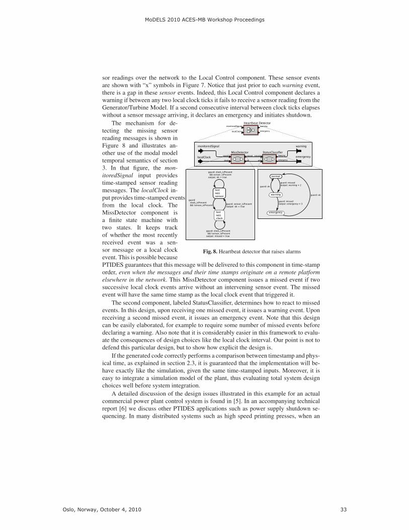
sor readings over the network to the Local Control component. These sensor eventsare shown with “x” symbols in Figure 7. Notice that just prior to each warning event,there is a gap in these sensor events. Indeed, this Local Control component declares awarning if between any two local clock ticks it fails to receive a sensor reading from theGenerator/Turbine Model. If a second consecutive interval between clock ticks elapseswithout a sensor message arriving, it declares an emergency and initiates shutdown.
Fig. 8. Heartbeat detector that raises alarms
The mechanism for de-tecting the missing sensorreading messages is shown inFigure 8 and illustrates an-other use of the modal modeltemporal semantics of section3. In that figure, the mon-
itoredSignal input providestime-stamped sensor readingmessages. The localClock in-put provides time-stamped eventsfrom the local clock. TheMissDetector component isa finite state machine withtwo states. It keeps trackof whether the most recentlyreceived event was a sen-sor message or a local clockevent. This is possible becausePTIDES guarantees that this message will be delivered to this component in time-stamporder, even when the messages and their time stamps originate on a remote platform
elsewhere in the network. This MissDetector component issues a missed event if twosuccessive local clock events arrive without an intervening sensor event. The missedevent will have the same time stamp as the local clock event that triggered it.
The second component, labeled StatusClassifier, determines how to react to missedevents. In this design, upon receiving one missed event, it issues a warning event. Uponreceiving a second missed event, it issues an emergency event. Note that this designcan be easily elaborated, for example to require some number of missed events beforedeclaring a warning. Also note that it is considerably easier in this framework to evalu-ate the consequences of design choices like the local clock interval. Our point is not todefend this particular design, but to show how explicit the design is.
If the generated code correctly performs a comparison between timestamp and phys-ical time, as explained in section 2.3, it is guaranteed that the implementation will be-have exactly like the simulation, given the same time-stamped inputs. Moreover, it iseasy to integrate a simulation model of the plant, thus evaluating total system designchoices well before system integration.
A detailed discussion of the design issues illustrated in this example for an actualcommercial power plant control system is found in [5]. In an accompanying technicalreport [6] we discuss other PTIDES applications such as power supply shutdown se-quencing. In many distributed systems such as high speed printing presses, when an
MoDELS 2010 ACES-MB Workshop Proceedings
Oslo, Norway, October 4, 2010 33

emergency shutdown signal is received, one cannot simply turn off power throughoutthe system. Instead, a carefully orchestrated shutdown sequence needs to be performed.During this sequence, different parts of the system will have different timing relation-ships with the primary shutdown signal. As presented in [6], this relationship is easilycaptured in the timed semantics of PTIDES.
5 Conclusion
This paper reviewed Ptolemy II enhancements for several important aspects of CPSdesign and deployment, namely PTIDES for distributed real-time systems, and modalmodels for multi-mode system behavior. The timed semantics of PTIDES allows us tospecify the interaction between the control program and the physical dynamics in thesystem model, independent of underlying hardware details. Because of this indepen-dence, PTIDES models are more robust than typical real-time software, because smallchanges in the physical execution timing of internal events are not visible to the en-vironment, as long as real-time constraints are met at sensors, actuators and networkinterfaces. By combining PTIDES with modal models, we illustrated timed mode tran-sitions which enable time-based detection of missing signals to drive mode changes inthe operation of common industrial applications.
Our future activities include work on several components of the PTIDES frame-work. PTIDES relies on software components providing information about model delaythey introduce. This information is captured by causality interfaces [27], and causalityanalysis is used to ensure that DE semantics is preserved in an execution. The precisecausality analysis when modal models are allowed is undecidable in general, but weexpect that common use cases will yield to effective analysis. Another challenge is toprovide feasibility analysis for the PTIDES programming model, which would allowfor a static analysis of the deployability of a given application on a set of resources.
A major component of our work will be refinement to the design of a distributedexecution platform for PTIDES. The code generator integrated within the Ptolemy IIenvironment will generate C code from PTIDES models and glue them together withthe preexisting software components to produce executable programs for each of theplatforms in the network. The code will be executed in the context of PtidyOS that canbe considered as a lightweight operating system with PTIDES semantics.
References
1. G. Berry. The effectiveness of synchronous languages for the development of safety-criticalsystems. White paper, Esterel Technologies, 2003.
2. S. Bliudze and J. Sifakis. The algebra of connectors: structuring interaction in bip. InEMSOFT, pages 11–20. ACM, 2007.
3. C. G. Cassandras. Discrete Event Systems, Modeling and Performance Analysis. Irwin, 1993.4. K. M. Chandy and J. Misra. Distributed simulation: A case study in design and verification
of distributed programs. IEEE Transaction on Software Engineering, 5(5), 1979.5. J. C. Eidson. Measurement, Control, and Communication Using IEEE 1588, pages 194–200.
Springer, London, 2006.6. J. C. Eidson, E. A. Lee, S. Matic, S. A. Seshia, and J. Zou. Time-centric models for de-
signing embedded cyber-physical systems. Technical Report UCB/EECS-2009-135, EECSDepartment, University of California, Berkeley, Oct 2009.
MoDELS 2010 ACES-MB Workshop Proceedings
Oslo, Norway, October 4, 2010 34

7. J. Eker, J. W. Janneck, E. A. Lee, J. Liu, X. Liu, J. Ludvig, S. Neuendorffer, S. Sachs,and Y. Xiong. Taming heterogeneity—the ptolemy approach. Proceedings of the IEEE,91(2):127–144, 2003.
8. D. Harel. Statecharts: A visual formalism for complex systems. Science of Computer Pro-
gramming, 8:231–274, 1987.9. IEEE Instrumentation and Measurement Society. 1588: IEEE standard for a precision clock
synchronization protocol for networked measurement and control systems. Standard speci-fication, IEEE, July 24 2008.
10. M. Jersak. Timing model and methodology for autosar. In Elektronik Automotive. Special
issue AUTOSAR, 2007.11. G. Karsai, J. Sztipanovits, A. Ledeczi, and T. Bapty. Model-integrated development of em-
bedded software. Proceedings of the IEEE, 91(1):145–164, 2003.12. H. Kopetz and G. Bauer. The time-triggered architecture. Proceedings of the IEEE,
91(1):112–126, 2003.13. E. A. Lee. Modeling concurrent real-time processes using discrete events. Annals of Software
Engineering, 7:25–45, 1999.14. E. A. Lee. Finite state machines and modal models in ptolemy ii. Technical Report
UCB/EECS-2009-151, EECS Department, University of California, Berkeley, Nov 2009.15. E. A. Lee and A. Sangiovanni-Vincentelli. A framework for comparing models of computa-
tion. IEEE Transactions on Computer-Aided Design of Circuits and Systems, 17(12):1217–1229, 1998.
16. E. A. Lee and H. Zheng. Leveraging synchronous language principles for heterogeneousmodeling and design of embedded systems. In EMSOFT, Salzburg, Austria, 2007. ACM.
17. P. Levis, S. Madden, D. Gay, J. Polastre, R. Szewczyk, A. Woo, E. Brewer, and D. Culler.The emergence of networking abstractions and techniques in tinyos. In First USENIX/ACM
Symposium on Networked Systems Design and Implementation (NSDI 2004), 2004.18. X. Liu and E. A. Lee. CPO semantics of timed interactive actor networks. Theoretical
Computer Science, 409(1):110–125, 2008.19. R. Makowitz and C. Temple. FlexRay-a communication network for automotive control
systems. In 2006 IEEE International Workshop on Factory Communication Systems, pages207–212, 2006.
20. Mathworks. Matlab. http://www.mathworks.com/products/matlab/, 1996.21. R. Olfati-Saber, J. A. Fax, and R. M. Murray. Consensus and cooperation in networked
multi-agent systems. Proceedings of the IEEE, 95(1):215–233, 2007.22. O.M.G. U.m.l. specification Version 1.3. Object Management Group, 1999.23. OMG. Uml profile for modeling and analysis of real-time and embedded systems (marte).
http://www.omgmarte.org/, 2008.24. K. Tindell, H. Hansson, and A. Wellings. Analysing real-time communications: Controller
area network (CAN). In Proceedings 15th IEEE Real-Time Systems Symposium, pages 259–265. Citeseer, 1994.
25. B. P. Zeigler, H. Praehofer, and T. G. Kim. Theory of Modeling and Simulation. AcademicPress, 2nd edition, 2000.
26. Y. Zhao, E. A. Lee, and J. Liu. A programming model for time-synchronized distributedreal-time systems. In Real-Time and Embedded Technology and Applications Symposium
(RTAS), Bellevue, WA, USA, 2007. IEEE.27. Y. Zhou and E. A. Lee. Causality interfaces for actor networks. ACM Transactions on
Embedded Computing Systems (TECS), 7(3):1–35, 2008.28. J. Zou, S. Matic, E. Lee, T. Feng, and P. Derler. Execution strategies for ptides, a program-
ming model for distributed embedded systems. In Real-Time and Embedded Technology and
Applications Symposium (RTAS), San Francisco, CA, USA, 2009. IEEE.
MoDELS 2010 ACES-MB Workshop Proceedings
Oslo, Norway, October 4, 2010 35