Embed Size (px)
Citation preview

IEEE TRANSACTIONS ON COMMUNICATIONS, VOL. 45, NO. 6, JUNE 1997 701
A Three-Stage ATM Switchwith Cell-Level Path Allocation
Martin Collier, Member, IEEE
Abstract—A method is described for performing routing inthree-stage asynchronous transfer mode (ATM) switches whichfeature multiple channels between the switch modules in adjacentstages. The method is suited to hardware implementation usingparallelism to achieve a very short execution time. This allowscell-level routing to be performed, whereby routes are updated ineach time slot. The algorithm allows a contention-free routing tobe performed, so that buffering is not required in the intermediatestage. An algorithm with this property, which preserves the cellsequence, is referred to here as a path allocation algorithm.A detailed description of the necessary hardware is presented.This hardware uses a novel circuit to count the number of cellsrequesting each output module, it allocates a path through theintermediate stage of the switch to each cell, and it generatesa routing tag for each cell, indicating the path assigned toit. The method of routing tag assignment described employs anonblocking copy network. The use of highly parallel hardwarereduces the clock rate required of the circuitry, for a given switchsize. The performance of ATM switches using this path allocationalgorithm has been evaluated by simulation, and is describedhere.
Index Terms—Asynchronous transfer mode, communicationswitching, communication system routing.
I. INTRODUCTION
T HE THROUGHPUT achievable (in bits/second) in anasynchronous transfer mode (ATM) switch depends heav-
ily on the process used to fabricate it. For example, Bianchiniand Kim [1] have described a single-board switch prototypewith 155-Mb/s link rate and a throughput of 2.48 Gb/s, con-structed using “off-the-shelf” integrated circuits and PLD’s.Collivignarelli et al. [2] have described a 1616 switch chipwith a 311-Mb/s link rate (and hence, with a throughput closeto 5 Gb/s) fabricated using a 0.8m BiCMOS process, whichdissipates 7 W. Merayoet al. [3] have reported a switch witha 10-Gb/s throughput and a 2.5-Gb/s link rate, using a 0.7-mBiCMOS process and requiring approximately twenty chips.Hino et al. [4] have developed a 44 switching element (fora rerouting banyan network) with link rates of 10 Gb/s usinga 0.2- m GaAs MESFET technology. The power dissipatedby this switch (some 30W) necessitates its implementation onthree integrated circuits.
It may be concluded, from the results reported above,which are typical of the current state of the art, that thetradeoffs to be performed between circuit complexity, power
Paper approved by G. P. O’Reilly, the Editor for Communications Switch-ing of the IEEE Communications Society. Manuscript received July 3, 1995;revised December 1, 1995.
The author is with the School of Electronic Engineering, Dublin CityUniversity, Glasnevin, Dublin 9, Ireland.
Publisher Item Identifier S 0090-6778(97)04172-X.
dissipation and process cost in designing ATM switches aresuch as to restrict single-chip and single-board switch fabricsto throughputs below perhaps 40 Gb/s for the foreseeablefuture, even when using leading-edge (and thus expensive) ICtechnologies. Hence, alarge switch fabric (i.e., a switch witha throughput exceeding, say, 200 Gb/s) will require a modulararchitecture, allowing the switch fabric to be distributed acrossmultiple boards or cabinets.
An obvious method of implementing a large switch, giventhese constraints, is to design the switch with three stages,where each stage consists of smaller switch modules. Manyauthors have proposed such switches [5]–[9]. This approachtypically introduces a new problem (not present in a single-stage switch) whereby multiple paths from source to desti-nation become available. Thus even if the individual switchmodules possess the self-routing feature, this feature is notretained by the overall switch. Some method of routing is thennecessary, to select among the available paths from source todestination, through the second stage of the switch.
Routing may be performed over a number of time scales.In one approach (call-level routing), all cells belonging to avirtual connection (“call”) are allocated the same route. Thusthe routing decision is made at connection setup time, andthis route is fixed for the duration of the connection.Cell-level routing is performed if the routing decision is madeindependently in each time slot. The process of determininga routing pattern such that no blocking can occur in thesecond stage of the switch is referred to here ascell-levelpath allocation.
This paper considers cell-level path allocation, and, specif-ically, the problem of implementing a cell-level algorithm forpath allocation in the channel-grouped three stage network ofFig. 1. This is an switch, with , andmodules in the input, intermediate and output stages, respec-tively. There are links in the channel group connecting inputand intermediate stage modules, andlinks in the channelgroup connecting intermediate and output stage modules. Theuse of channel grouping allows additional flexibility whendimensioning the three-stage switch. Cell-level path allocationhas been proposed by a number of authors [5]–[7]. Thealgorithm described here requires fewer iterations than thatin [6], does not require input buffering (which degrades thethroughput), unlike [7], and is fairer than that presented in[5], in addition to readily supporting intermediate channelgrouping.
The path allocation algorithm and the hardware necessaryto implement it are described in Section II of this paper.
0090–6778/97$10.00 1997 IEEE
702 IEEE TRANSACTIONS ON COMMUNICATIONS, VOL. 45, NO. 6, JUNE 1997
Fig. 1. A three-stage switch with intermediate channel grouping.
The algorithm requires ancillary hardware to count incomingcells and to deliver routing tags to them. Suitable hardwareis described in Sections III and IV of this paper. The switchperformance is discussed in Section V.
II. A N ALGORITHM FOR PATH ALLOCATION AT CELL LEVEL
A. The Objectives of a Path Allocation Algorithm
There are routes from each input module to each inter-mediate module. There are routes from each intermediatemodule to each output module. We must choose, for everyinput cell (if possible) an intermediate switch module throughwhich to pass on the way to the selected destination, such thatno input module attempts to route more thancells via anyintermediate module, and no intermediate module attempts toroute more than cells to any output module, in any onetime slot. This strategy ensures that:
1) the intermediate stage can never be congested;2) no queueing occurs in the intermediate stage; thus the
delay through the intermediate stage is uniform, regard-less of the path taken; this makes it possible to preservecell sequence on a virtual connection;
3) contention can never occur in the intermediate stage,simplifying its design.
An algorithm to implement this strategy will now be de-scribed. It will be assumed, for simplicity, that all input ports ofthe switch operate at the same rate, and thus that the duration ofthe time slot (the interval between successive cell boundaries)is the same for every cell.
B. Basic Principles of the Path Allocation Algorithm
A new and efficient algorithm will now be described. It issuitable for use in a channel-grouped three-stage switch andrequires only knowledge obtainable at the input side of theswitch. It operates on the following quantities:
number of channels available from input moduletointermediate switch modulenumber of channels available from intermediate switchmodule to output modulenumber of requests from input modulefor outputmodule .
(a)
(b)
Fig. 2. Examples of the processor array (a) showing contents of processorsduring Iteration Zero(L1 = L2 = m = 4) and (b) showing initial conditionsfor L1 = 2;m = 4, andL2 = 3.
Note that and need only be local to the inputmodule. The ’s must be forwarded to each input modulein turn. Let be the number of cells to be routed frominput module to output module via intermediate switchmodule The values of and are updated usingthe procedure described below:
This procedure is “atomic” in the sense that it is the basicbuilding block from which the path allocation algorithm isconstructed. The procedure determines the capacity availablefrom input module to output module via intermediateswitch module (i.e., the minimum of and . Thenumber of requests which can be satisfied is equal to theminimum of the number of requests outstanding andthe available capacity.
A parallel implementation requires multiple processors, eachexecuting the procedure for a different set ofprocedure parameters, subject to the following constraints:
• no two processors shall simultaneously requireaccess to the same quantity. For example,
uses and so that neithernor
can be executed concurrently with forany ;

COLLIER: A THREE-STAGE ATM SWITCH 703
Fig. 3. Implementation of theatomic( ) processor. Min: Calculator of minimum;Dx: Delay (needed to synchronise arrival times—may be zero).
• the data required by a processor for the next iteration ofthe algorithm should be available locally, or from adjacentprocessors.
An implementation satisfying these two constraints will nowbe presented.
C. Implementation of the Algorithm
Suppose that there are modules in each stage of theswitch. An array of processors is used. The processorin the th row (numbered from the right) andth column(numbered from the bottom) of the array is labeled .Processor is initialized by loading the following threevalues:
1) initial value of ;2) initial value of (i.e., ;3) initial value of (i.e., .
The values stored in the processor array are shown inFig. 2(a) for the case where .
The algorithm then requires iterations (iterations zerothrough . Processor executes
during iteration ; after each iterationforwards the updated value of to and of
to , and retains .If we choose the same algorithm
may be used for a switch with an arbitrary number of modulesin each stage. Suppose that a square array ofprocessors is used. Some of the processor registers must beinitialized to zero if their contents pertain to a nonexistentswitch module. Specifically, processor is initialized asfollows:
otherwise.
otherwise.
otherwise.
where .
An examination of the operation of the resulting algorithmreveals that the processors in row or higher and in column
or above never modify the and values they receive,and thus may be replaced by simple delays.
In general, a switch with input modules and outputmodules requires a processor array with rows andcolumns. If , each column requires additional
registers. If , each row requires additionalregisters. The initial conditions in the array for the case where
and are shown in Fig. 2(b).An unichannel architecture may require a large value forto obtain low cell loss probabilities. Hence a relatively
high clock speed will be required in the array, so as tocomplete iterations of the algorithm in the time available(which is less than the duration of one time slot). A switchwith intermediate channel grouping affords the possibilityof reducing cell loss probability by increasing and ,rather than by increasing This can reduce the clock speedrequirements. Note that, unlike the cell scheduling algorithmin [5], this algorithm attempts to allocate a path toeachcellat the switch inputs duringevery iteration of the algorithm.Thus, the proposed algorithm is fairer than that describedin [5].
D. Implementation Issues
The processor must execute the procedure, andthus must perform two types of operation:
1) find the minimum of three numbers;2) perform three subtractions.
Hence, in principle, the processor may be implemented asshown in Fig. 3. The value of is stored locally. Theand values are obtained from (and forwarded to) adjacentprocessors. The simple structure of the processorensures that many copies of it may be constructed on a singleintegrated circuit (IC), and also ensures that it can operate athigh speed. A fast implementation using bit-serial arithmetic,and which does not require the calculation of the minimum ofthree numbers, was described in [10].

704 IEEE TRANSACTIONS ON COMMUNICATIONS, VOL. 45, NO. 6, JUNE 1997
Fig. 4. The circuitry for request counting and routing tag assignment. CG: Count generator; RPG: Routing packet generator; AG: Address generator.
Hardware is also needed in each input module to perform thefollowing tasks before and during the path allocation process:
• to count the number of requests for each output moduleso as to obtain the initial values of the ’s;
• to forward a routing tag based on the results of pathallocation to each input cell.
The circuitry to implement these functions is shown inFig. 4. Its operation will be described in Sections III and IV.
It is assumed that cells losing contention are discarded. Ifthis is not the case, additional hardware will be required toforward acknowledgments to the input port controllers, andthis circuitry will introduce an additional delay.
The switch fabric, as described above, operates at asingle rate (which will typically be the OC-3/STM-1 rateof 155 Mb/s). The input and output port controllers mustperform the necessary bit rate adaptation (and multiplex-ing/demultiplexing) for links operating at other rates, sothat cells traverse the switch fabric at a common rate. Thedemultiplexing of incoming cell streams of high bit rate to anumber of switch fabric inputs has implications for the switchperformance (since correlations are then possible betweenthe arrival processes on adjacent input ports), and for cellsequence preservation, which will be addressed in a futurepaper.
The switch will be required to support multiple loss prior-ities in practice. This requires the path allocation algorithmto preferentially allocate paths to cells with the CLP bitset to zero. The simplest way of modifying the describedalgorithm to achieve this is to perform path allocation twice,once for cells with CLP , and a second time for thecells tolerating higher loss rates, with the initialization of theprocessor array being appropriately modified. However, thisapproach doubles the required operating speed of the array,which may be impractical in many cases. A less expensivemethod for introducing differentials in loss probabilities isdescribed in [11].
III. A F AST METHOD OF REQUEST COUNTING
Suitable hardware to simultaneously calculate (thenumber of requests from input modulefor output module
for all values of will now be described.The execution time for this hardware is
clock cycles. A slower solution, requiring less hardware, wasdescribed in [12].
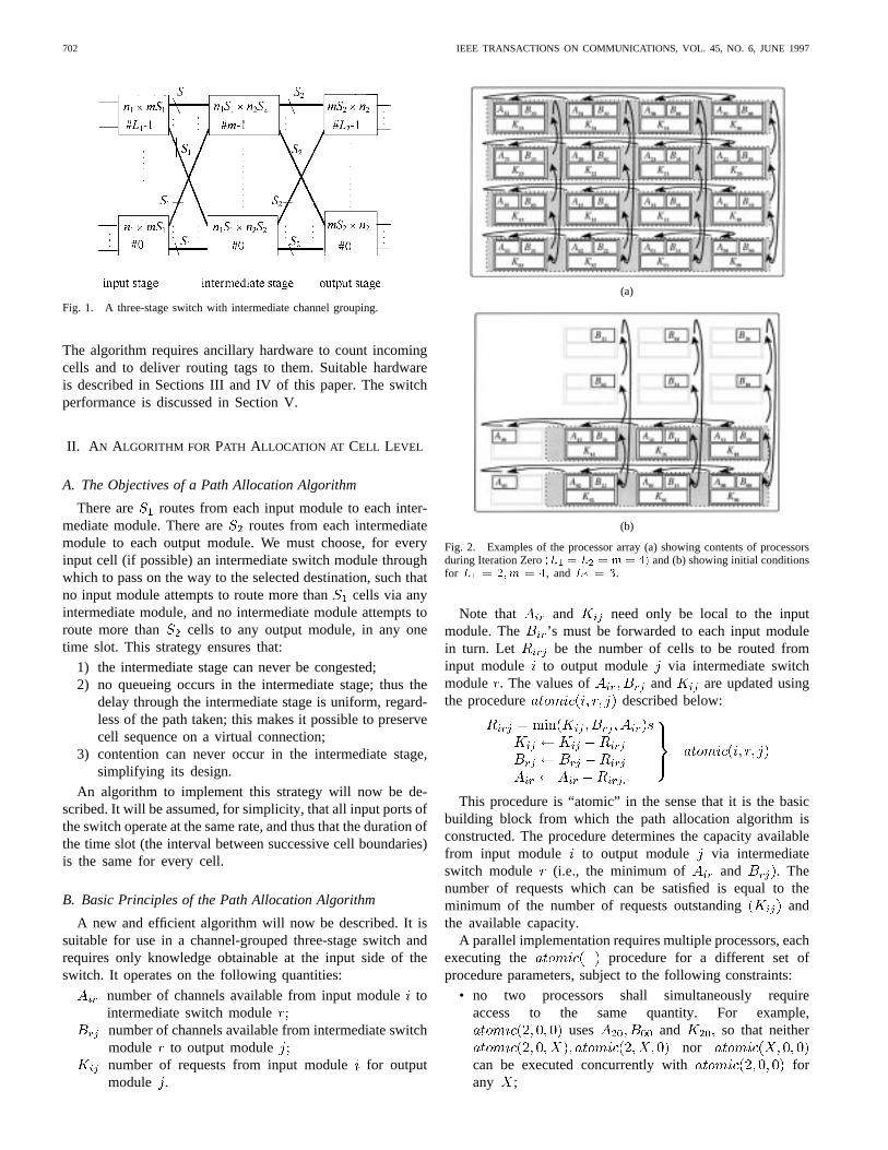
The hardware required is shown in Fig. 5. Data cells fromthe input ports associated with input moduleare mergedwith control packets (one per output module) by a Batchersorting network. The merge operation is performed in such away that idle cells (i.e., empty cells from inactive input ports)are sorted to the highest output ports of the Batcher network.If the control packet for output moduleappears at outputof the Batcher network, then the data cells (if any) requestingthat output module appear at lower output ports of the sorter(ports etc.), as shown in Fig. 5.
Under these circumstances, it may readily be shown that
where is the number of data cells requesting outputmodule , and is fixed, since the Batcher network processesonly requests from input module.
The key to this method of request counting is the obser-vation that
The necessary subtraction can be performed very efficiently,since
where is the 1’s complement of obtained by bitwiseinversion of It follows that the value of can begenerated using a serial adder, and can then be stored in theregister of the appropriate processor (i.e., of
It is necessary to generate a concentrated list of the valuesas input data for the serial adders.
These values are obviously available at the sorter outputswhich have received control packets (since, for example, con-trol packet 4 appears at output , but are not concentratedonto contiguous outputs. Hence a concentrator is required. Thisis the purpose of the binary self-routing network shown inFig. 5, which is often called the “reverse banyan” [13]. Awell-known property of this network is that it is nonblocking
COLLIER: A THREE-STAGE ATM SWITCH 705
Fig. 5. An example of request counting. CG: Count generator.
when acting as a concentrator. A formal proof that blockingcannot occur in Fig. 5 was given in [14].
The count generators forward only control packets to thisnetwork. Count generators which have received a data cellor an idle cell through the Batcher network submit an inactivepacket to the concentrator. The count generator which receivescontrol packet from output of the Batcher networkappends a data field to the packet containing the value of
This packet is then routed to outputof the concentrator.A total of control packets is thus simultaneously launchedinto the concentrator, and these are routed to the serial addersat outputs zero through without blocking.
The concentrated list of values is then read by theseserial adders, the lower input (as shown in Fig. 5) beinginverted. Hence the values are generated, and passed to the
processors. The example considered in Fig. 5 showsthree requests for output module zero, two for output moduleone, and none for output module two. It can be seen thatthe correct values (i.e., 3, 2 and 0) are returned to processors
and , respectively.The submitted packets take two cycles to propagate through
each stage of the concentrator (one cycle to identify if thepacket is active, and another to determine where to route it)and an additional clock cycle is required before the serial addergenerates the least significant bit of the appropriatevalue.Thus the number of clock cycles required by the request counthardware before path allocation can commence is
Hence, for a switch with and , the numberof clock cycles required is just 15.
IV. ROUTING TAG ASSIGNMENT
A. Principles of Operation
The processor generates a sequence ofvalues, one after every iteration of the path allocation
algorithm, commencing with (the initial value of
determined by the request counting hardware) and decrement-ing, after every iteration, in accordance with theprocedure, as paths are allocated to cells. Thusrepresentsthe number of outstanding requests from input moduleforoutput module . The relevant cells must be informed of thepath through the intermediate stage which they have beenassigned. The relevant information is obtained from theoutput of the processor shown in Fig. 3. After each iterationof the algorithm, tokens are broadcast to cellsby the circuitry for routing tag assignment. A cell may receivemultiple tokens, but only the last token it receives containsvalid routing information. When the path allocation process iscomplete, a special null token is broadcast to the cells whichhave lost contention. The address generator then prefixes arouting tag to each data cell whose value equals the tokenvalue. Cells losing contention are marked as inactive.
The broadcasting is done by the copy network shown inFig. 4. This must copy tokens and perform routing in such away that the token required by the data cell at a given Batchernetwork output in Fig. 4 appears at the corresponding copynetwork output, and is thus received by the correct addressgenerator.
The copy network has inputs and outputs. Therouting packet generators are connected to of the copynetwork inputs, and the remaining inputs are idle. Routingpacket generator receives the value of from theappropriate processor.
The cells requesting output module appear at outputsthrough of the Batcher network, where
(as before)
The routing packet generator for output modulemust forward the relevant routing tokens to the data cells atoutputs through of the Batcher network.The value of is readily obtainable from the requestcounting hardware.

706 IEEE TRANSACTIONS ON COMMUNICATIONS, VOL. 45, NO. 6, JUNE 1997
(a) (b)
(c) (d)
(e)
Fig. 6. An example of routing tag assignment. (a) Initialization (i.e., iteration0�). (b) Iteration0+: (c) Iteration1+. (d) Iteration2+. (e) Iteration3+. Thetype of token being broadcast is shown on the input and output sides of the copy network. The type of packet receiving the token, and the value of the last tokenreceived, are shown at the network outputs (clearly only data cells receive tokens, as required). RPG: Routing packet generator; ISM: Intermediate stage module.
During each iteration of the algorithm, submits arouting packet to the copy network, to be broadcast to addressgenerators through containing in thedata field the token address, i.e., the address of the intermediateswitch module through which a route has been allocated. If
an inactive packet is submitted.The routing packets submitted to the copy network do not
collide, since they satisfy the condition for avoiding internalcontention in the copy network, as shown in [10].
The copy network is based on that described by Lee[15]. Lee’s copy network uses the ‘Boolean interval splittingalgorithm’ to generate copies at each copy network element.Two bits (one each from the upper and lower address), inaddition to the activity bit, must be processed at each node ofthe network. Hence, the interval between successive iterationsof the algorithm, in bit times, will be quite large. The speedof the algorithm can be increased by observing that, in thisapplication, the lower address bit processed at each node never

COLLIER: A THREE-STAGE ATM SWITCH 707
(a) (b)
(c)
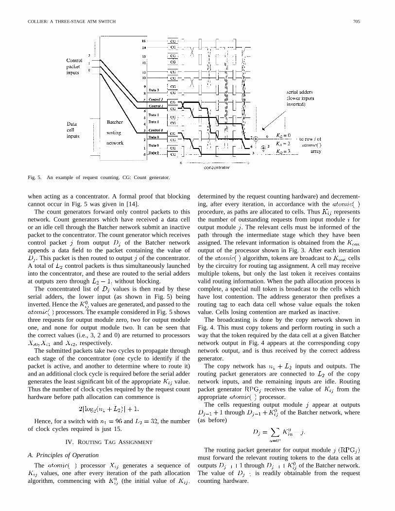
Fig. 7. Performance of the switch. (a) Performance with uniform traffic(L1 = m = L2; S1 = S2 = 4): (b) Performance with uniform traffic(L1 = m = L2; S1 = 8; S2 = 4): (c) Performance with uniform traffic(L1 = m = L2; S1 = 4; S2 = 8).
TABLE IPATTERN OF REQUESTS AND POSSIBLE
OUTCOME OF THE PATH ALLOCATION PROCESS
changes after the first iteration of the algorithm [16]. Hence,on subsequent iterations of the algorithm, there is no need todistribute the lower address, so that the header on the routingpacket may be shortened, reducing the delay through the copynetwork.
B. An Example of Routing Tag Assignment
The example is documented in Tables I and II, and in Fig. 6.It describes a possible outcome of path allocation for a switchwith four modules in each of the three stages.
Table I indicates the number of cells from input module 0which have requested each of the four output modules
and a possible pattern of path allocations which might be
generated by the processors. The copy networkmust be initialized before path allocation commences. Thiscorresponds to iteration in Table II and occurs simultane-ously with iteration 0 of the path allocation algorithm. Aftereach iteration of the path allocation algorithm (i.e., iterations0, 1, 2 and 3), the corresponding iteration of the routing tagassignment algorithm is performed (iterations and
respectively). Thus, for example, iteration of the routingtag assignment algorithm occurs concurrently with iteration 2of the path allocation algorithm. The required broadcasts areshown in Table II and illustrated in Fig. 6(a)–(e). Also shownare the lower address bits processed by each switch element. Itcan be seen that these bits never alter after the initial iterationof the algorithm. After five iterations, the correct number ofcells has been assigned a path via each intermediate stagemodule.
The length of each routing packet (after the first) is
i.e., one activity bit, enough bits to represent the token address,and sufficient bits to represent the requested upper copynetwork output.

708 IEEE TRANSACTIONS ON COMMUNICATIONS, VOL. 45, NO. 6, JUNE 1997
TABLE IIVALUES OFK REGISTERS, ANDADDRESSES TOWHICH TOKENS ARE BROADCAST, IN EACH ITERATION, FOR THE EXAMPLE OF TABLE I
Hence, routing packets may be submitted to the networkat the rate of one every clock cycles. If this exceedsthe number of clock cycles required for one iteration of thepath allocation algorithm, an undesirable delay is introduced,whereby the path allocation can only proceed at the rate ofone iteration per clock cycles.
A solution to this difficulty involves a reduction in thevalue of . The token address is not broadcast, except duringthe first iteration. The address generator stores the tokenaddress received during the first iteration, and on subsequentiterations calculates the token address by decrementing theprevious value. Therefore, the value of can be reduced by
bits.Once path allocation is complete, the tag allocation process
requires only a further
clock cycles to terminate (this being the time required togenerate the final null routing packet, and to propagate itthrough the copy network). A cheaper method of routing tagassignment was described in [12], where the ‘over-run’ timeonce path allocation has concluded increases linearly with thesum of and .
V. PERFORMANCE OF THEPATH ALLOCATION ALGORITHM
The performance of a three-stage switch using the cell-level path allocation algorithm described above will now beevaluated. The cell loss probability must be determined bysimulation since no analytical method is currently available.The simulation model is based on the following assumptions.
1) There is no input queueing; cells which are not allocateda path on the first attempt are discarded.
2) The switch is offered a worst-case (maximum) load; eachinput port of the switch submits a cell in every timeslot.
3) The destination of each cell is drawn from a uniformdistribution; all output modules receive the same load.
4) The switch modeled is that shown in Fig. 1, for variouschoices of the parameters and .
5) The maximum number of cells generated is 10. Ifzero cell loss is recorded during the simulation, the cellloss probability is assigned the value 510 . Theprobability of losing contention during path allocationis assumed to be independent for each cell, at low levelsof loss. With this assumption, the probability that thecell loss probability (CLP) is below 5 10 , giventhat no losses were recorded, is above 95%, i.e.,
6) When cell losses are observed, the cell loss probabilityis assumed to be equal to the expected number ofcells lost per time slot, as a proportion of the offeredload.
(Note that if the fifth assumption) is not made, a value canonly be assigned to the probability of cells being lost from theset of input ports, rather than from one input port, when no lossis observed. Specifically, if a simulation runs for 500 000 timeslots without loss being observed, the probability that cell losswill be observed in an arbitrary time slot is below 2.610 atthe 5% significance level, sinceThis is for an offered load of typically 3000 cells/time slot forthe simulations described here. The probability of an individualcell being lost is obviously much less, but cannot be evaluatedwithout knowing how the probability of a given cell losingcontention, and the corresponding probabilities for the cellswith which it contends, are correlated.)
The influence of the choice of channel group size in Fig. 1on the cell loss probability is considered in Fig. 7. The graphsshow how the cell loss probability varies as a function of thenumber of input ports, with the capacity of the intermediatestage fixed. Confidence intervals have not been shown, but areobviously moderate for probabilities above about 10, wheremany cell losses have been recorded. The results where
are shown in Fig. 7(a). Note that for thethree switches simulated. Fig. 7(b) shows the correspondingresults for three similar switches, where equals 8. Doublingthe channel group size at the input side of the intermediatestage gives rise to only a marginal decrease in the cell lossprobability. Doubling the channel group size at the outputside of the intermediate stage reduces the loss considerably,as shown in Fig. 7(c).
These simulations indicate that the intermediate modulesshould be designed as expansion modules, with more outputsthan inputs, to obtain the best performance. This seems intu-itively reasonable; a cell may be routed to any intermediatemodule, but can be routed to only one output module. Analternative to increasing is to change the value of . How-ever, this has the disadvantage that the number of iterationsrequired by the path allocation algorithm will increase, sothat higher speed hardware may be required. These graphscan be used to find the maximum number of input portswhich a switch with a given capacity in the intermediate stagecan support, for a given probability of cell loss during pathallocation.
Further simulation results, including an investigation ofthe performance in the presence of nonuniform loads, arepresented in [14].

COLLIER: A THREE-STAGE ATM SWITCH 709
VI. A D ESIGN EXAMPLE
A 3072 3072 switch can be constructed by choosingand
in the switch shown in Fig. 1. The resulting switch has acell loss probability (due to loss of contention during pathallocation) below 10 even in the presence of a nonuniformload [14]. The input modules must accept data from theaddress generators in Fig. 4, and so must have 128 inputs,even though at most 96 data cells will be present. Thedimensions of the input, intermediate and output stage modulesare 128 128, 128 256, and 256 96, respectively. The inputand intermediate modules can be of simple design, since theyare contention-free. Thus the only stage of the switch whichrepresents a major design challenge is the output stage, wherethe 256 96 switch modules should also introduce a low cellloss probability.
The process of path allocation should be completed withinone time slot. The request counting hardware requires
clock cycles. One executionof the procedure will require nine clock cycles,using the efficient implementation described in [10]. Thus288 (9 32) cycles are needed to test all possible paths. Thenumber of processors required is 1024 (3232), but the ICcount should be relatively low because of the simplicity ofthe processor design. Broadcasting null tokens to cells losingcontention requires an additionalclock cycles, for a total of 325 clock cycles. Hence the clockrate required should be below 130 MHz (for operation atthe STM-1 rate), including some additional overhead. Thisindicates that a CMOS or BiCMOS VLSI implementation ofthe path allocation circuitry should be possible.
The resulting switch features a level of cell delay variationwhich is no worse than that of a single-stage switch, becausecells are buffered only in the output stage. The complexity ofthe path allocation circuitry is relatively high, but the switchmodules in the first and second stages are of simple design,because of the avoidance of output contention. The author iscurrently investigating the practical implementation of the pathallocation circuitry, with a view to confirming that the overallcomplexity of the switch is no greater than that of competingarchitectures, such as those in [5]–[9].
VII. CONCLUSIONS
A new algorithm for path allocation in three-stage broad-band networks has been described. A complete hardwareimplementation of this algorithm has been presented, includinga method for generating the initial data required by the algo-rithm, and for forwarding the results to each cell at the inputside of the switch, in the form of a routing tag. The operatingspeed required of the design appears within the capabilities ofVLSI technology in the short term. The performance of thealgorithm has been investigated, and the additional flexibilityoffered in dimensioning the switch when intermediate channelgrouping is supported has been demonstrated. The resultingswitch offers the delay performance of an output-bufferedswitch, unlike either three-stage switches featuring call-levelrouting, which buffer the cells at each stage, or those featuringinput buffers. It avoids the fairness problem intrinsic to the
“cell scheduling” algorithm of the Growable Packet Switch [5].It thus represents a viable architecture for the implementationof a large ATM switch.
ACKNOWLEDGMENT
The author gratefully acknowledges the assistance of hiscolleague Tommy Curran in the preparation of this paper.He also thanks the anonymous reviewers for their helpfulcomments.
REFERENCES
[1] R. P. Bianchini and H. S. Kim, “The Tera project: A hybrid queueingATM switch architecture for LAN,” IEEE J. Select. Areas Commun.,vol. 13, pp. 673–685, May 1995.
[2] M. Collivignarelli, A. Daniele, P. De Nicola, L. Licciardi, M. Turolla,and A. Zappalorto, “A complete set of VLSI circuits for ATM switch-ing,” in Globecom ’94 Conf. Rec., San Francisco, CA, Dec. 1994, pp.134–138.
[3] L. A. Merayo, P. L. Plaza, P. Chas, G. Piccinni, M. Zamboni, and M.Barbini, “Technology for ATM multigigabit/s switches,” inGlobecom’94 Conf. Rec., San Francisco, CA, Dec. 1994, pp. 117–122.
[4] S. Hino, M. Togashi, and K. Yamasaki, “Asynchronous transfer modeswitching LSI chips with 10 Gb/s serial I/O ports,”IEEE J. Solid-StateCircuits, vol. 30, pp. 348–352, Apr. 1995.
[5] K. Y. Eng, M. J. Karol, and Y.-S. Yeh, “A growable packet (ATM)switch architecture: design principles and applications,”IEEE Trans.Commun., vol. 40, pp. 423–430, Feb. 1992.
[6] A. Cisneros, “Large packet switch and contention resolution device,”in Proc. Int. Switching Symp., Stockholm, Sweden, 1990, vol. III, pp.77–83.
[7] J. Hui and T.-H. Lee, “A large-scale ATM switching network with sort-banyan switch modules,” inGlobecom ’92 Conf. Rec., Orlando, FL,Dec. 1992, pp. 133–137.
[8] A. Jajszczyk and W. Kabacinski, “A growable ATM switchingfabric architecture,”IEEE Trans. Commun., vol. 43, pp. 1155–1162,Feb./Mar./Apr. 1995.
[9] W. E. Denzel, A. P. J. Engbersen, and I. Iliadis, “A flexible shared-buffer switch for ATM at Gb/s rates,”Comput. Networks ISDN Syst.,vol. 27, no. 4, pp. 611–624, 1995.
[10] M. Collier, “Switching techniques for Broadband ISDN,” Ph.D. disser-tation, Dublin City University, Dublin, Ireland, July 1993.
[11] , “Loss priorities in a three-stage multi-rate ATM switch,” Tech.Rep. EE/BSSL/9S/1, Sch. of Elect. Eng., Dublin City Univ., Dublin,Ireland, 1995.
[12] M. Collier and T. Curran, “Path allocation in a three-stage ATM switchwith intermediate channel grouping,” inProc. INFOCOM ’93, SanFrancisco, CA, Mar.–Apr. 1993, pp. 927–934.
[13] H. S. Kim and A. Leon-Garcia, “Nonblocking property of reversebanyan network,”IEEE Trans. Commun., vol. 40, no. 3, pp. 472–476,Mar. 1992.
[14] M. Collier and T. Curran, “Cell-level path allocation in a three-stageATM switch,” in ICC’94 Conf. Rec., New Orleans, LA, May ’94, pp.1179–1183.
[15] T. T. Lee, “Nonblocking copy networks for multicast packet switching,”J. Select. Areas Commun., vol. 6, pp. 1455–1467, Dec. 1988.
[16] M. Collier, “High-speed cell-level path allocation in a three-stage ATMswitch,” in Globecom’94 Conf. Rec., San Francisco, CA, Nov. 1994,pp. 324–328.
Martin Collier (S’87–M’93) was born in Drogheda,Ireland, in 1964. He received the B.Eng. and M.Eng.degrees in electronic engineering at the NationalInstitute for Higher Education, Dublin, in 1986 and1988 respectively, and the Ph.D. degree from DublinCity University, Dublin, Ireland, in 1993.
He is currently a lecturer in the School of Elec-tronic Engineering at Dublin City University, wherehe runs the Broadband Switching and Systems Lab-oratory. His research interests include broad-bandswitching, switching network topology, and sig-
nalling in ATM networks.