Embed Size (px)
Citation preview

Universitat Bremen
Diplomarbeit
A Testbed Framework Design for Protocol
Development and Evaluation in Wireless Mobile
Ad-Hoc and Delay Tolerant Networking
Environments
Alle Rechte vorbehalten.
Vorgelegt dem Fachbereich Informatik
der Universitat Bremen
Bremen, den 16. Dezember 2006
von: Christoph Dwertmann
Matrikel-Nr.: 1437662
1. Gutachterin: Prof. Dr.-Ing. Ute Bormann,
Universitat Bremen
2. Gutachter: Prof. Dr. Jorg Ott,
Helsinki University of Technology


Contents
List of Figures v
List of Tables vii
Listings ix
1 Introduction 1
2 Use Cases and Requirements 3
2.1 Use Cases . . . . . . . . . . . . . . . . . . . . . . . . . . . . . . . . . . . . 3
2.2 Requirements . . . . . . . . . . . . . . . . . . . . . . . . . . . . . . . . . . 9
2.3 Conclusion . . . . . . . . . . . . . . . . . . . . . . . . . . . . . . . . . . . . 14
3 Related Work 15
3.1 Technology Candidates . . . . . . . . . . . . . . . . . . . . . . . . . . . . . 16
3.2 Complete Solutions . . . . . . . . . . . . . . . . . . . . . . . . . . . . . . . 28
4 Architecture and Implementation 33
4.1 Architecture . . . . . . . . . . . . . . . . . . . . . . . . . . . . . . . . . . . 33
4.2 Components . . . . . . . . . . . . . . . . . . . . . . . . . . . . . . . . . . . 42
4.3 Compatibility . . . . . . . . . . . . . . . . . . . . . . . . . . . . . . . . . . 55
4.4 Deployment . . . . . . . . . . . . . . . . . . . . . . . . . . . . . . . . . . . 55
4.5 Open Issues . . . . . . . . . . . . . . . . . . . . . . . . . . . . . . . . . . . 56
5 Application: Extending AODV with DTN 59
5.1 Integrating DTN and MANET Routing . . . . . . . . . . . . . . . . . . . . 59
5.2 Testbed Setup . . . . . . . . . . . . . . . . . . . . . . . . . . . . . . . . . . 69
5.3 Implementation and Testing . . . . . . . . . . . . . . . . . . . . . . . . . . 71
5.4 Measurements and Observations . . . . . . . . . . . . . . . . . . . . . . . . 77
5.5 Conclusion . . . . . . . . . . . . . . . . . . . . . . . . . . . . . . . . . . . . 85
iii

6 Prospects and Conclusion 89
6.1 Future Work . . . . . . . . . . . . . . . . . . . . . . . . . . . . . . . . . . . 89
6.2 Conclusion . . . . . . . . . . . . . . . . . . . . . . . . . . . . . . . . . . . . 94
A Installation Instructions 97
Glossary 103
Bibliography 107

List of Figures
2.1 MANET Scenario: Plane Crash Site . . . . . . . . . . . . . . . . . . . . . . 4
2.2 Drive-thru Internet Scenario . . . . . . . . . . . . . . . . . . . . . . . . . . 6
2.3 Symbian Series60 Phone Platform Emulator . . . . . . . . . . . . . . . . . 8
3.1 Basic Testbed Concept . . . . . . . . . . . . . . . . . . . . . . . . . . . . . 16
3.2 Mobility Emulator (MobE) Screenshot . . . . . . . . . . . . . . . . . . . . 19
3.3 Nam: Visualising a Wireless Network (Screenshot) . . . . . . . . . . . . . 26
4.1 Architecture of the Kasuari Framework . . . . . . . . . . . . . . . . . . . . 34
4.2 Overview: Networking . . . . . . . . . . . . . . . . . . . . . . . . . . . . . 36
4.3 Overview: Filesystems . . . . . . . . . . . . . . . . . . . . . . . . . . . . . 39
4.4 Overview: Trace Files . . . . . . . . . . . . . . . . . . . . . . . . . . . . . . 41
5.1 Increasing the Reach of Communications . . . . . . . . . . . . . . . . . . . 64
5.2 AODV Packet Extension containing DTN Router Info . . . . . . . . . . . . 66
5.3 Optional AODV Packet Extensions containing Source and Target EID . . . 67
5.4 Chain Topology . . . . . . . . . . . . . . . . . . . . . . . . . . . . . . . . . 70
5.5 Number of AODV Messages sent in different Testbed Configurations . . . . 79
5.6 Total AODV Message Volume sent in different Testbed Configurations . . . 80
5.7 Tool Setup for AODV-DTN Measurements . . . . . . . . . . . . . . . . . . 82
6.1 MIRAI-SF Screenshot . . . . . . . . . . . . . . . . . . . . . . . . . . . . . 91
6.2 iNSpect Screenshot . . . . . . . . . . . . . . . . . . . . . . . . . . . . . . . 92
v


List of Tables
5.1 Number of AODV Messages sent in different Testbed Configurations . . . . 79
5.2 Total AODV Message Volume sent in different Testbed Configurations . . . 80
5.3 Message Delivery Rate at different DTN Densities . . . . . . . . . . . . . . 84
vii


Listings
4.1 Xen Entry in the grub Bootloader Configuration File . . . . . . . . . . . . 44
4.2 Network Objects and Tap Agents in a ns-2 Simulation Script . . . . . . . . 47
4.3 Sample kasuari.cfg (excerpt) . . . . . . . . . . . . . . . . . . . . . . . . 52
4.4 Startup Script to set domU Host Name (excerpt) . . . . . . . . . . . . . . 53
4.5 Testbed Master Script Example (auto.sh) . . . . . . . . . . . . . . . . . . 54
5.1 Chain Topology iptables Script . . . . . . . . . . . . . . . . . . . . . . . . 71
5.2 DTN Router Info Extension Type . . . . . . . . . . . . . . . . . . . . . . . 72
5.3 DTN Router Info Extension Handler . . . . . . . . . . . . . . . . . . . . . 74
5.4 Sample Contents of /var/log/aodvd.dtnlog . . . . . . . . . . . . . . . . 75
5.5 Sample Commands sent to dtnd . . . . . . . . . . . . . . . . . . . . . . . . 76
ix

Abstract
Network protocol development requires a testbed where complex networking scenarios
can be set up in a realistic setting to validate their proper operation and to assess their
performance. This diploma thesis introduces the Kasuari framework, meant to address
the requirements of a wireless networking testbed for Mobile Ad-Hoc Network (MANET)
protocols and Delay Tolerant Networking (DTN) applications. It features modern virtu-
alisation technology, supports protocols implemented as Linux kernel module or userspace
program and has an interface to a flexible, widely used (wireless) network simulator.


Chapter 1
Introduction
In recent years wireless networks became ubiquitous. Falling hardware prices as well as
improvements in transmission speed, reliability and power requirements brought mobile
network devices into many aspects of life. The success of this technology led to a multitude
of new, innovative applications and protocols for different purposes. Especially Mobile Ad-
hoc Networking (MANET) became a popular field of research. It allows mobile nodes
to organise themselves arbitrarily without prior configuration, maintaining links to each
other and propagating routing information. This can be beneficial in areas with little or
no communication structure, such as remote accident sites or less developed countries. A
recent and popular example where MANET technology is in use today is the much-hyped
MIT Media Lab hundred dollar laptop that is able to instantly communicate with other
laptops in its vicinity.
The testing and evaluation of MANET protocols and applications is a necessary but
time-consuming process. Developers are required to validate the correct software behaviour
in a realistic setting. Re-enacting a typical MANET scenario by fitting wireless devices
with the prototype implementation and moving them around is obviously impractical and
tedious. Therefore, developers may look into automating tests and measurements in a
wireless network testbed.
The purpose of this diploma thesis is to define the requirements for a testbed suitable for
MANET protocol development, analyse existing testbed techniques and solutions as well
as to design, implement and validate the Kasuari framework. The Kasuari framework is a
flexible and scalable wireless network testbed of the next generation. It combines emerging
technologies such as paravirtualisation and real-time network simulation/emulation and is
pre-packaged for easy installation on one of the major Linux distributions. It consists of
1

2 Chapter 1: Introduction
Free Software components only, completely avoiding licensing issues and high costs, and is
freely available for anyone to download and use.
In this diploma thesis, a unique approach is taken to validate the performance of the
Kasuari framework in a protocol development scenario. A certain use case that emerged
from recent research work is implemented, tested and validated thoroughly and the process
is meticulously documented within this work. The idea of enhancing the Ad-hoc On
Demand Distance Vector (AODV) routing protocol with Delay Tolerant Networking (DTN)
to improve communication in sparse mobile wireless networks led to a proposed extension of
the AODV protocol. This extension was implemented in a Linux kernel module and user-
space daemon. From early testing during the development phase to thorough stability
testing of the final code and measuring the performance gained by the extension, the
Kasuari framework was the proving ground used in all stages. The measurement results
obtained in the testbed were mentioned in a recent paper publication[OKD06].
The work undertaken in the course of this thesis is the testbed design and the creation of
the ”script glue” that is necessary for the components to interact and execute the testbed
scenario. Most components had to be modified in order to co-operate with the others.
Furthermore, a Debian GNU/Linux guest system had to be created and modified for quick
testbed node bootup and compatibility, and the whole framework including kernel images,
modules, tools and filesystems for different platforms was packaged for easy installation
in the Debian GNU/Linux distribution. Similar effort went into the development, testing
and performance measurements of an application use case (the AODV-DTN extension).
In chapter 2 this diploma thesis begins with the description of three use cases taken
from the research context. Common requirements for a testbed environment are derived
from these use cases. In the next chapter (3), existing testbed components are examined
and evaluated for possible integration in our framework. Furthermore, a picture of existing
testbed solutions is drawn, comparing them to our approach. Chapter 4 depicts the archi-
tecture and implementation of the Kasuari framework, respectively. Chapter 5 documents
the AODV-DTN integration use case thoroughly, including background information on
the technologies used. The design and implementation process is described, measurement
results are presented and a conclusion is drawn. The thesis concludes with an account
of possible future development of the Kasuari framework in chapter 6 and installation
instructions in appendix A.

Chapter 2
Use Cases and Requirements
In section 2.1 of this chapter three possible use cases for a wireless network emulation
environment are introduced. They depict specific and common application scenarios where
such a testbed would aid in development and testing of new software concepts. The next
section (2.2) then lists and discusses common requirements for the testbed deduced from
the use cases. External requirements are also taken into account. Finally, the requirements
are summarised in the conclusion of this chapter (section 2.3) and a first picture of the
upcoming solution is drawn.
2.1 Use Cases
The three use cases described in this section are actual scenarios that emerge from current
research projects. For all of them, a wireless network testbed would speed up development,
testing and help understand processes in all details.
2.1.1 Evaluating MANET Routing Protocols
A mobile Ad-hoc Network (MANET) is a wireless network with self-configuring nodes.
They independently move around and organise themselves to communicate, but as the
network topology is unpredictable and may rapidly change, paths may not sustain long
and communication may be unreliable. Nodes are usually willing to forward data, thus
playing the the roles of traditional wired networks components (such as routers, switches
and hubs) not found in a MANET. They may relay data packets across several hops using
the wireless links that are currently established between them. As no or only minimal
3

4 Chapter 2: Use Cases and Requirements
initial node configuration is necessary, such networks can be deployed quickly even in
environments with no other network infrastructure.
Figure 2.1: MANET Scenario: Plane Crash Site
For the self-configuration and route finding in a MANET to work, an Ad-Hoc routing
protocol is necessary. Nodes may optionally announce their presence via broadcast using
this protocol while listening to other node’s announcements in order to learn about adjacent
nodes and possible routes. Besides announcing their sheer presence, nodes may additionally
communicate their whole routing table, their geographical location or statistics about past
node encounters. Many different Ad-hoc routing protocol approaches exist, each tailored
to specific networking scenarios.
A typical scenario where a MANET routing protocol would be useful is a plane crash
occurring in a rural area with no communication infrastructure (figure 2.1). Different
emergency vehicles (ambulances and fire trucks in the illustration) rush to the scene from
various directions, only very few of them having a satellite uplink to the Internet. Police,
paramedics, military and investigators spread over a possibly large area and use their lap-
tops and PDAs. They all have various communication needs while searching for survivors
and evidence. Their devices (laptops, mobile phones, PDAs) are nodes in a spontaneous,
unreliable and sparse wireless network. There is no time to set up an infrastructure (e.g.
base stations) covering the whole area and configure all participating clients to use it.
Consequently, a mobile Ad-Hoc network can be used to dynamically adjust to the unpre-
dictable, fluctuating topology. Routes are established across several nodes to reach certain

2.1 Use Cases 5
communication partners, especially the ones functioning as a gateway to the outside world.
In order for all this to work in an emergency situation, the MANET protocol used is cru-
cial to the success and needs to be carefully evaluated as well as thoroughly tested for its
suitability and reliability.
This is a very specific example for this use case, but the routing protocol required to
deal with this situation is rather generic, as it basically requires the nodes to self-configure
in order to provide a functional wireless network with optimised routes. To decide which
protocol works best for a certain task, performance measurements of promising candidates
in a realistic setting prior to roll-out is advisable. Existing protocol implementations may
exist for simulated nodes or for real node operating systems. Those should be installed in a
deterministic testbed environment, and automated tasks should trigger protocol actions to
generate comparable measurement results. To avoid influences from the outside world that
may spoil the measurements, any aspect of the testbed should be controllable. It should
also be flexible and scalable enough to cover rare and challenging network scenarios. In
order to understand the protocol behaviour and to evaluate whether it is suitable in a given
setting, measurement results should be saved to detailed trace files and if possible visualised
automatically. Thus, a fair comparison between promising candidates is facilitated.
2.1.2 Drive-Thru-Internet
A specific wireless, mobile ad-hoc networking scenario is Internet access from motor vehicles
on a highway. As many highways in most countries today are covered by infrastructure cel-
lular networks that can be used for phone calls and low to medium speed data transfer, by
default many motorists will use them for their personal communication needs. A rather in-
expensive alternative, that also provides higher data rates, is roadside wireless LAN access
points. This broadly available technology provides intermittent — largely unpredictable
and usually short-lived — connectivity. Not all typical Internet applications handle inter-
mittent connectivity well, therefore a supportive Drive-thru architecture was introduced.
A session protocol called Persistent Connectivity Management Protocol (PCMP) is meant
to offer an end-to-end data transmission behaviour to applications designed for persistent
connectivity. Instead of communicating directly with each other, a client and a server
talk to PCMP entities like a Drive-thru client and a Drive-thru proxy. PCMP maintains
reliable TCP sessions in presence of intermittent connectivity and address changes[OK05].
In the development and testing of PCMP and the Drive-thru architecture, measurements

6 Chapter 2: Use Cases and Requirements
Figure 2.2: Drive-thru Internet Scenario
were performed in a car driving along a certain part of the German autobahn. The car
was equipped with a laptop running the Drive-thru client software and a roof-mounted
WLAN antenna. Multiple access points with high-gain antennae were placed along the
road on a parking lot, connected to a Drive-thru proxy via the Internet (as in figure 2.2).
The distance between them lead to periods with no connectivity in the car, their duration
depended on the current speed. To measure the maximum data throughput and to verify
the PCMP implementation, a TCP connection was established from the car through the
proxy to an application server (e.g. using FTP) at the beginning of the first connectivity
phase. The client sends as much data as possible while the connection sustains and PCMP
keeps the TCP session alive across the disconnection period.
The real life tests on the autobahn are obviously elaborate. The setup on the parking lot
and in the car takes time, as well as the measurements at different speeds testing different
software configurations. At least three people (driver, car experimenter and parking lot
experimenter) are necessary, and outside influences such as bad weather, radio interference
2.1 Use Cases 7
or lots of traffic may affect the results observed. Development and testing cannot be coupled
as the autobahn testing strip is not within close proximity to the lab. The experimenters
even got into some trouble with the authorities once. All these experiences tell that a
lab-based testbed would significantly reduce the time between development and testing
phases. Outside influences could be virtually eliminated, as the testbed conditions are
almost always exactly the same. This would also lead to comparable measurement results.
The testbed could as well scale to multiple vehicles passing the access points at the same
time, something which would be even harder to achieve in reality. A powerful visualisation
tool could display the current traffic flow, while detailed measurement data is written to
trace files for later analysis.
2.1.3 Development for Mobile Platforms
Today mobile devices with wireless connection options are in widespread use. Most PDAs
(Personal Digital Assistants) support the IEEE 802.11 Wireless LAN standard1, while
more and more phones equipped with that technology are currently emerging. With an
increasing number of people carrying these devices in their pockets, short-range device
intercommunication becomes a popular subject among network operators, phone produc-
ers and independent software developers. After the recent success of ”social networking”
services on the Internet, many ideas focus on sharing content and personal details with
other people in a close range.
A possible ”social networking” application for 802.11-equipped phones might involve the
continuos announcement of the device presence and its capabilities in an ad-hoc wireless
LAN. The capabilities could include messaging and personal details as well as photo,
audio and video sharing. Users might use this to exchange data with their peers or make
new contacts in their vicinity. As phones find each other, their users might initiate data
transfers. The file transfer protocol used should be capable to deal with sudden link outages
that might happen when interference occurs or the communication partners move out of
range.
In order to implement such a software for a mobile platform, usually a Software Devel-
opment Kit (SDK) is used. It runs on a regular computer and is provided by the platform
distributor. Most of the time, the SDK can be downloaded free of charge and comes with
extensive documentation, allowing almost anyone to develop applications for the target
1http://standards.ieee.org/getieee802/802.11.html

8 Chapter 2: Use Cases and Requirements
platform on their home computer. During the development and testing phase, the pro-
grammer can either copy the software to the device to test it there, or run it in an emulator.
The emulator, if provided, is obviously the better approach since it does not require the
tedious process of copying the binary files over a slow Bluetooth or USB connection to
the device after each compilation. Instead, the mobile platform is emulated on the local
machine, behaving like the actual device in a window on the desktop. Most emulators also
support debugging and virtual network devices that can be attached to the host machine’s
network adapter. The screenshot in figure 2.3 shows the Series60 platform emulator from
the Symbian/Nokia SDK2.
Deploying the Client and Application to an Emulator DEPLOY THE CLIENT AND APPLICATION
Running the Application on an Emulator
Now on your Nokia Series 60 emulator you can go to the "Other" folder from the "Applications" menu to seeicons both for the Crossfire client and for your Hello World application.
Figure 36: Nokia Series 60 Emulator with New Icons
Select your Hello World application and click the Push Me! button several times to see your Crossfire applicationin action:
Figure 37: Nokia Series 60 Emulator Running Hello World
20
Figure 2.3: Symbian Series60 Phone Platform Emulator
The development and testing phase of the application proposed in this use case is carried
out mostly in the emulator, although the emulator is not able to reproduce realistic wireless
networking scenarios. It merely provides a gateway to the Internet and to possible other
emulators running on the same or another machine. To test the software capabilities in
a challenged network environment, a network testbed could be attached to the virtual
network adapters of multiple emulator instances. Different scenarios should be playable in
2http://www.forum.nokia.com/

2.2 Requirements 9
the testbed, simulating conditions like congestion, weak signals or link breaks. The number
of nodes should scale to large scenarios, ensuring that the software works as intended even
in crowded areas. A visualisation tool should display the current network conditions in
real-time to allow programmers to trigger certain events in the emulator testing specific link
conditions. Network topologies and movement patterns should accommodate various user
behaviour such as walking around (random walk), driving on a freeway (Freeway model) or
moving along streets aligned in a chessboard layout (Manhattan model)[BSA03]. A network
testbed could provide for all those testing needs, reducing the amount of elaborate real-life
tests.
2.2 Requirements
In this section, common requirements for a testbed that derive directly or indirectly from
the use cases are denoted, also taking external requirements into account. This list is not
exhaustive, but contains more general descriptions of the important features a wireless
networking testbed should bear in order to satisfy the use cases. They do not limit the
possible testbed usage scenarios to the use cases presented, but rather try to be open and
flexible while obeying monetary restrictions. The requirements listed are criterions that
will later be used to evaluate existing solutions in chapter 3 and to design our testbed in
chapter 4.
2.2.1 Derived Requirements
The following requirements are derived either directly or indirectly from the use cases:
Scalability. The smallest scenario to test a typical MANET protocol (e.g. the one de-
scribed in chapter 5) for proper operation would require about five nodes. More
sophisticated tests in a realistic setting probably requires 20 to 50 nodes, stress test-
ing in a setting with a high node density would exceed 100 nodes. Our testbed should
be able to scale to these dimensions without performance penalties or excessive re-
source usage on off-the-shelf hardware. Software support for distributed computing
to increase the scalability is desired but not required, as clustering solutions exist
that are able to distribute the workload of non-distributed software across several

10 Chapter 2: Use Cases and Requirements
machines (e.g. openMosix3).
Flexibility. Our use cases are not limited to certain hardware platforms, certain operating
systems, certain network technologies or topologies. Therefore the testbed should not
have these restrictions either. According to the use cases, there is popular demand
for Linux support, as many MANET implementations are available for that plat-
form. Linux distributions are available for a wide range of CPU architectures. They
are found in various environments from tiny hand-held devices to large server farms.
Linux enables hardware platform independence and in many cases cross-platform
code portability. It is Free Software and therefore can be extended without limita-
tions. Linux is the most flexible operating system and is the preferred choice, but
we are not limited to it. The testbed network should be flexible as well, supporting
established wired network technology like Ethernet as well as wireless connectivity
options like 802.11 (Wireless LAN), Bluetooth, GPRS, EDGE, 3G and so on. The
option set should not be fixed, but extensible to network technologies that currently
do not exist.
Topology. Different wireless networking scenarios require different node behaviour. A typ-
ical Drive-thru-Internet topology would include some access points along a stretch
and some fast moving wireless nodes. Other scenarios would require similar or com-
pletely different topologies. The wireless network testbed should allow for complex
network topologies incorporating commonly used node mobility models, such as the
random walk, random way-point, Freeway and Manhattan models. Support for input
from existing mobility model generation utilities is desirable.
Realism. In the Drive-thru-Internet use case presented in the previous section, one of the
challenges is to find out how much data can actually be transferred from and to a
car passing an access point at different velocities. Real-life tests on the autobahn
are elaborate, therefore a testbed measurement setup providing realistic results is
desirable. Three major challenges arise in achieving that goal: accurate scenario
design, realistic wireless network characteristics and proper protocol behaviour. The
scenario design should reflect a real-life wireless networking situation close to reality.
The wireless network should behave as realistically as possible, including typical
effects such as interference, reflection, refraction and attenuation. Finally, protocol
implementations should behave in the same way as they do in real world applications.
3http://openmosix.sourceforge.net/

2.2 Requirements 11
Another factor contributing to the realism of a wireless network testbed is random-
ness. In real life there are many sources of randomness: radio interference, random
node and obstacle movements, weather conditions that affect the radio signal as well
as random retransmission intervals and scheduling effects on the wireless node. To
be able to compare a series of measurement results from the testbed, it is sometimes
desirable to eliminate any differences between the test runs. However, the initial test
parameters should include realistic randomness and typical third-party interference.
Control level. A perfect wireless networking testbed would be a system completely isolated
from any influence of the surrounding environment. Anything that happens inside
of it would be controlled by the experimenter. Although this is hardly feasible,
a maximum level of control is desirable. A common source of external influence
in a wireless network testbed is third-party radio interference from other network
equipment (e.g. Bluetooth adapters, 802.11 equipment) or other transmitters (e.g.
microwave oven, garage door opener) in the neighbourhood. These external influences
are not to be confused with the desired randomness and interference that should be
specified within the testbed scenario to make it realistic, as described in the previous
paragraph. External, unwanted interference may spoil the measurements and render
them irreproducible and incomparable, shielding against them is one step towards a
higher level of testbed control.
Determinism. The behaviour of a real-life wireless network is not deterministic. Many in-
ternal and external sources of randomness (as listed in the previous paragraphs) lead
to more or less different measurement results on each run. For some experimenters
this might not be a problem, as slight variations in the packet flow are often negligible
and the average values of several runs may comprise the result. During protocol fine-
tuning and optimisation, the experimenters however may want to eliminate as much
differences due to randomness as possible between the testbed measurements. Espe-
cially the node movement should reiterate accurately. Additionally, a deterministic
testbed behaviour allows for comparison between testbed installations in different lo-
cations. Not only the input and output file formats should be unified (as described in
the Comparability paragraph below), but also the the actual measurement outcome
in a certain scenario should be the same, no matter where the testbed is installed.
If scientists all over the world are able to rebuild the exact wireless network testbed
used in a paper publication, they can directly compare their work with others, which
would be a huge step ahead.

12 Chapter 2: Use Cases and Requirements
Automation. Wireless network testbed setup and testing can be tedious. Nodes and
wireless equipment need to be installed and placed correctly. The software running
in the testbed must be set up and application events must be scheduled to occur at
the desired time. In addition, the node movement has to be timed and performed
numerous times for each test run. After each run, log files must be stored and all
testbed components need to be reset to their original, pre-run state. Test automation
by scripting should be adopted wherever possible to minimise the setup effort and
to reduce human error. For easy scripting, a command line interface to all software
tools is desirable.
Tracing. The most important (and sometimes most elaborate) part of the wireless network
testbed operation is done after the test runs are completed. This being the analysis
of the measurement data collected during the runs. All relevant network activity
should be logged, as well as per-node software events (e.g. routing table changes,
application logs) and hardware details (e.g. CPU load, memory usage). Especially
the packet traces should be logged in a common file format to make use of various
existing analysis tools.
Comparability. The scenario topology, movement model, network configuration, node con-
figuration and log file formats should be based on existing standards. This would
allow experimenters all over the world to compare the input and output of each
testbed component, even if they do not use our testbed implementation. Addition-
ally, the configuration of all applications on the nodes in the testbed should be similar
or the same in order to receive comparable log and trace files from the nodes after
the testbed run.
Visualisation. As wireless network traffic is not visible in mid-air, and it’s hard to tell
what exactly happens in a closed simulator/emulator box, visualisation is a key
factor to understand and debug the events in a wireless networking scenario. During
a measurement run, all testbed events should be logged to files, and, if applicable,
node movements in a real-life scenario should be recorded with a video camera and/or
positioning devices. This allows the experimenter to view the testbed events either
in real-time during the run, or at various speeds after the run. Trace files can be used
to display network and node events in a visualisation tool. It should show the node
locations and their movement graphically, visualise the network traffic and be able
to colour the nodes according to their current protocol role (e.g. sender, receiver or
forwarder).

2.2 Requirements 13
2.2.2 External Requirements
Additional requirements are given by the university research environment under which this
thesis work was developed:
Hardware acquisition and operation costs. Keeping a wireless network testbed up to
date with emerging technologies can be quite costly. A low cost testbed should
only require a few off-the-shelf hardware components and be low maintenance in op-
eration. The more nodes and network components are installed, the higher is the
testbed’s power consumption. This should be kept as low as possible for economical
and ecological reasons.
Licensing. Typically, Free Software is very popular in and around universities. Software
licences may cost a great deal of money, and proprietary solutions are not always
the best when it comes to research and development. Non-free or non-public testbed
software and documentation would hinder other research institutions from using it,
exchanging their results within the research community or even improving upon it.
The testbed should therefore be published under the terms of the GNU General
Public Licence (GPL)4 or a similar Free Software licence in order to distribute, use
and modify it freely.
Physical space requirements. Most universities and research institutes may not have ex-
tensive room capacity for a large indoor or outdoor wireless network testbed. Only
military research centres may have access to really large testbeds: they can occupy
extensive testing grounds in a secured environment and with their resources com-
prised of humans and various vehicles, performing realistic outdoor tests of radio
equipment. As we are not aiming for military application of our testbed, but want
to make the testbed operation affordable to anyone, it should definitely fit into a
normal computer laboratory, the less space it consumes the better.
Testbed setup effort. Setting up and upgrading the testbed hard- and software should
be easy, quick and fail-proof, so chances are higher that other researchers will at-
tempt using it. Especially in university research environments, time and manpower
is usually limited.
4http://www.gnu.org/copyleft/gpl.html

14 Chapter 2: Use Cases and Requirements
2.3 Conclusion
The three use cases presented in this chapter are examples for upcoming research challenges
that would greatly benefit from a testbed environment for wireless networking applications.
They are sharing many of the demands on a possible testbed environment that emanate
from them. In addition to the challenges that emerge from the use cases there are external
requirements listed that can play a significant role in a university research environment,
but also in companies. Those mainly arise from monetary limitations, thus ensuring that
not only researchers on a high budget can afford to run the testbed.
The requirements are listed and described in detail and lay out the feature set for the
upcoming solution presented in this thesis. As the use cases particularly stress requirements
such as scalability, flexibility, determinism and comparability, it becomes clear that a
self-contained testbed that is shielded from uncontrollable, unwanted outside influences
is desirable and that as many components as possible should be implemented in software,
allowing for high scalability at low hardware cost. Especially regarding the physical space
and operation cost limitations, it seems likely that hardware nodes and network devices
positioned in a lab testbed do not scale and therefore do not meet the requirements.
Software solutions are able to simulate or emulate parts of the network and the mobile
nodes. But before making a final decision on how to build our testbed solution, we are
taking an in-depth look at simulation and emulation technologies and will compare them
to hardware testbed solutions in the next chapter.

Chapter 3
Related Work
In the context of this thesis, related work can be two different things. The one kind of
related work is existing ideas, projects, architectures or implementations which may be
suitable to serve as inspirations, starting points or actual components to build our testbed
solution on. Before building a whole new wireless networking testbed from scratch, it is
certainly worthwhile to analyse different existing concepts and technologies that may be
used as blueprints and building blocks to assemble the Kasuari framework. The other kind
of related work is complete network testbed solutions that aim for roughly the same goals
as our project does. In contrary to the technology candidates that may help us by being
the base of our testbed or a component of it, these related projects are competition.
This chapter is divided in two parts. In the first section (3.1), a closer look is taken
at existing techniques and promising components that may be used in a wireless network
testbed. For each category, several technology candidates are presented and in a final
evaluation the candidates that accommodate the requirements from the previous chapter
best are nominated. The goal is to find the most comprehensive testbed components
available today and combine them in a new way, building a complete testbed suite.
The second part of this chapter (section 3.2) sheds some light on existing network testbed
solutions that fulfil (a subset of) our requirements. Their benefits and limitations are
examined in a conclusion, pointing at possible pitfalls and misconceptions that should be
avoided in this work.
15
16 Chapter 3: Related Work
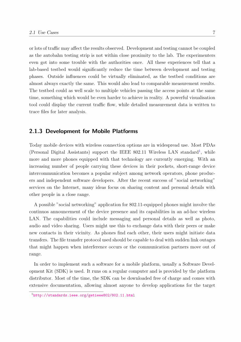
Figure 3.1: Basic Testbed Concept
3.1 Technology Candidates
In this section, the first part of this chapter, different technologies and solutions are pre-
sented that may be used to create testbed nodes and the testbed network. These are the
two main components of a generic network testbed as illustrated in figure 3.1. In this basic
concept, different testbed nodes communicate with each other over wired or wireless links
in the testbed network. Mobile nodes eventually move around in the testbed area, causing
wireless link to break and reform. Applications on the nodes may generate network traffic
that can be monitored in the testbed network for protocol evaluation.
For the testbed nodes and the testbed network, four classes of techniques can be dis-
tinguished: real hardware components, emulation, virtualisation and simulation. After
introducing the four different approaches, each section lists a selection of qualified existing
solutions that implement this technology and meet our requirements. Finally, a verdict is
given which candidates will be considered to build our testbed framework.
3.1.1 Real Hardware
A straightforward way to create a wireless network testbed for development and perfor-
mance evaluation of our use cases is to build it using real network hardware components.

3.1 Technology Candidates 17
Stationary or moving wired or wireless nodes can be placed in a lab and networked with
classic wired ethernet components (bridges, hubs, switches, routers and so on) or wire-
less LAN equipment (access points, range extenders, 802.11 ad-hoc mode cards et cetera).
Node types such as PDAs, mobile phones or laptops can be moved in the lab space to create
wireless mobility. This, however, is a tedious process when the devices are carried around
by humans. Exact scenario reproduction is hard to achieve, complex scenario setups may
require some training, and many experimenters simply won’t have the necessary human
resources on-hand to move the nodes around in the testbed manually. In fact, only military
research centres may have enough resources to run really large wireless mobility tests with
their vehicles and personnel in an outdoor area. Furthermore, in a real hardware testbed
the costs grow linear with the node count and wireless infrastructure, as the hardware must
be acquired.
One approach to this problem is to replace human wireless node carriers by machines.
Today’s off-the-shelf robots are able to manoeuvre in easy terrain while following defined
mobility patterns. They are small, affordable, quite reliable and can be remote controlled
from anywhere in the world. The School of Computing at the University of Utah has
created ”[...] the world’s first remotely accessible testbed for mobile wireless and sensor net
research”[JoL05]. Wireless devices are mounted on six small, two-wheeled robots (”motes”)
that researchers directly control using a web interface. Their movement precision is within
a one centimetre deviation and experimenters can track their every move via live video
streaming, maps and telemetry. The robotic testbed is open for researchers around the
world who can sign up on the project’s website1. A similar project, ORBIT2 provides
access to 400 static nodes, only supporting ”virtual mobility” by fixed nodes that only
appear to move.
Instead of making an effort by moving humans or robots to create node mobility, one
can also use existing mobility scenarios from everyday life as a testbed. An example is a
public transportation network: trains, buses and ferries can be equipped with wireless net-
work devices. They follow defined, scheduled routes in a constricted area, but are subject
to traffic conditions. Many transit corporations around the world are planning to roll out
wireless data services for commuters and some are willing to co-operate with researchers. A
successful co-operation exists since 2004 between the Pioneer Valley Transport Authority
(PVTA) and the University of Massachusetts Amherst. In their project, UMassDiesel-
Net, researchers equipped 30 public transportation buses each with a small computer, two
1http://www.emulab.net2http://www.orbit-lab.org/

18 Chapter 3: Related Work
802.11 wireless LAN cards and a GPS unit. The buses run on a daily basis, sparsely cov-
ering an area of 150 square miles in western Massachusetts. Wireless data is exchanged
with other buses, road-side access points and passenger devices over separate wireless chan-
nels. The testbed is mainly used to measure bus-to-bus transfers using different routing
protocols[BGJL06].
3.1.2 Emulation
Network emulation does not mean to emulate the network hardware in software. It rather
describes a technique where network properties such as delay, error rate, bandwidth, packet
loss or jitter are inserted into an existing network by adding an emulation device. This
device may be a dedicated hardware module or just a computer running network emulation
software. It allows to imitate challenged networking environments such as high-delay satel-
lite links, lossy wireless links or low-bandwidth modem lines, which may not be available
for testing in every lab. Those parameters can be set before running an experiment, and
altered instantly and dynamically during the procedure, thus allowing exact reproducibil-
ity. In summary, network emulation could be described as a mix of simulation and reality:
it simulates network properties in a real network.
Emulation is only considered for the network, but not for the actual nodes. Node em-
ulation means to recreate a complete set of hardware in software, e.g. to emulate an
architecture different from the actual platform it runs on. As each instruction has to be
translated from the emulated machine’s command set into the actual machine’s language,
the performance is massively degraded. Node emulation should only be considered in spe-
cial cases where it is absolutely necessary to emulate certain node hardware, for example
when the actual hardware is not or not yet available or extremely expensive and the testbed
node software does not run on any other platform.
Many hardware and software network emulation solutions exist on the market. Free
Software network emulators are highly flexible at no cost (except for the computer they
run on). The Linux kernel (starting at version 2.6.7) already includes a network emulator
called netem as part of its Quality of Service (QoS) and Differentiated Services (diffserv)
code. The kernel module is enabled by default in many pre-compiled distribution kernels
and is configured over the Netlink socket interface by a userspace tool package, iproute2.
This package includes the tc program used to assign queuing disciplines to Linux network
interfaces in the kernel. A queuing discipline has an input and an output queue and decides

3.1 Technology Candidates 19
which packets to send at what time based on the current settings. In the current version
of netem, only outgoing traffic is shaped. Supported shaping parameters include packet
delay, loss, duplication, reordering and rate control[Hem05]. To use netem to introduce
certain network properties into an existing network, one would set up a computer with
multiple network interfaces and assign the desired queuing disciplines to them. All traffic
to be shaped is then routed through that machine.
An alternative to netem is NIST-Net[CS03] which could be described as a ”network in a
box”. A specialised router applies user-supplied network parameters to passing traffic. In
the graphical user interface, parameters such as delay, loss, jitter, reordering, duplication
and bandwidth limitation can be controlled while statistics are displayed. NIST-Net is
implemented as a Linux kernel module, which is unfortunately not available for the latest
kernel versions, as the project is no longer maintained regularly.
Figure 3.2: Mobility Emulator (MobE) Screenshot
Another approach especially to emulate a mobile, wireless network is mobility emulation
by altering wireless signal power levels. This technique allows to create an illusion of
node mobility in a lab testbed without actually moving the nodes around. At National

20 Chapter 3: Related Work
Information and Communications Technology Australia (NICTA) we developed a Java-
based software, Mobility Emulator (MobE), that controls the output power levels of Cisco
Aironet 1200 access points via the Telnet interface. We generate mobility patterns either
by hand, by a simulation model using Markov chains or by using real world signal strength
measurements. The Mobility Emulator turns those patterns into signal strength levels and
sets the access point power levels accordingly during playback. A Java GUI allows us to
load patterns, play/pause their playback and visualise the signal strength values in a graph
as depicted in figure 3.2. The stationary wireless clients in the lab setting experience these
power adjustments in a similar way as if they were moving through a field of access points.
Mobility Emulator proved itself to be a helpful tool during Mobile IP network hand-over
experiments[LPP+05].
3.1.3 Virtualisation
Virtualisation is a technique that provides the ability to partition hardware in a way that
allows more than one operating system to run simultaneously. CPU instructions and
other hardware calls from the operating systems and applications are executed natively on
the hardware, while a virtualisation layer between them schedules concurrent requests for
the same resources, shielding the processes from each other. Only very few components
cannot be virtualised, therefore each virtual machine requires an emulated version of it
(e.g. network adapters, hard drive controllers). In contrast, emulators model the CPU
and most other subsystems in software so that each emulator instance can only run one
operating system instance.
Virtualisation is not a new approach, as hardware vendors are offering solutions for
high end systems for more than thirty years now, but with the ever increasing speed and
reliability of commodity hardware, virtualisation starts to hit the medium and low-end
hardware market as a viable solution for hardware consolidation. In a wireless network
testbed, virtualised nodes can replace real hardware nodes, saving hardware and operation
costs. By running many virtual nodes on a single machine, collecting trace files, test
automatisation and setup effort are greatly simplified[Zim06].
Full hardware virtualisation is not always necessary to isolate nodes and their applica-
tions from each other. The node applications could as well all run on the same operating
system, isolated only by different file system roots. This can be achieved in any Linux or
BSD distribution using the chroot command. Virtual network devices (such as TUN/TAP

3.1 Technology Candidates 21
devices3) provide isolated network devices, that can communicate with each other only if
the local routing table allows it. A similar isolation effect is achieved when using Security
Contexts4 that create an arbitrary number of secure, isolated environments. They are
executed on a single hardware machine and in a single operating system with a modified
kernel, requiring virtually no resources of their own.
All these solutions are sharing the same operating system kernel for the isolated shells.
Many network testbed setups may require different operating systems or at least different
kernels. Kernel modules cannot be configured differently for different instances, and most
kernel modules only support data structures for one instance. For example, the Linux
kernel only allows for one routing table at a time, therefore the isolated shells cannot have
differently configured tables of their own. Many routing protocols are designed as Linux
kernel modules and therefore will not work in these isolated environments.
User Mode Linux (UML) is unaffected by this problem. This kernel patch, integrated in
Linux 2.4 and 2.6, modifies the operating system code to run as a simple user mode process
on any unmodified Linux host. Loading different kernel modules for different instances is
not a problem. Each UML instance uses a fixed amount of system memory and is able
to mount an arbitrary filesystem on the host as the virtual machine’s root filesystem.
Network connectivity between host and UML can be established via various transports
such as TUN/TAP, Multicast or a software switch daemon[Dike05].
Running a full Linux kernel with fixed memory allocation for each testbed node has
some drawbacks. Firstly, emulation performance is severely hampered due to the fact that
UML runs in user mode and privileged operating system calls must be emulated by the
underlying kernel running on the real hardware. Consequently, context switches within
the virtual machine take up to 100 times longer than on a non-virtual Linux system. As
UML, just like any other user mode process, underlies the Linux scheduler, a host system
or an UML under heavy load may severely affect the other UML’s performance. Secondly,
the resource usage of UML is relatively inefficient, as the available system memory is not
dynamically distributed across the UMLs, but is set to a fixed amount on UML bootup.
Therefore, the maximum number of concurrent UML instances is limited directly by the
amount of system memory. A Linux 2.6 kernel needs at least 12 megabytes of RAM to boot,
20 megabytes are the bare minimum to run applications. The overall UML performance is
disappointing, even when enabling the SKAS mode (”Separate Kernel Address Space”) in
3http://vtun.sourceforge.net/tun/4http://linux-vserver.org/Paper

22 Chapter 3: Related Work
the host kernel[EFSH04].
The technologies presented so far are able to isolate node instances from each other by
resource partitioning. This is a kind of lightweight operating system virtualisation that
implies certain limitations (such as no kernel modules can be loaded) or low performance.
Full hardware virtualisation provides full and direct CPU and memory access from separate
virtual machines running different kernels. All other hardware is emulated, therefore device
drivers are necessary in each guest system and on the host. The host operating system
kernel requires no modifications. Popular products in this category are Microsoft Virtual
Server5 and VMWare GSX Server6. These expensive and proprietary products perform
better than UML, but the necessary driver layer to access hardware devices entails a
performance hit of 15-25% on virtual nodes compared to a non-virtualised node[Zim06].
The last approach to be mentioned in this section is paravirtualisation. In this case, the
host operating system needs to be modified to run on top of a hypervisor. The hypervisor
operates directly on the hardware, virtualising it for the host system and the guests. The
host operating system is basically a special kind of virtual machine, from where the guest
systems are created. The low-level hypervisor manages the system resources and may
dynamically adjust them at virtual machine runtime. Each guest uses the same driver
instances to access the hardware. Generally, the guest system kernel needs to be modified
for paravirtualisation as well as the host kernel. Hardware vendors eventually implement
paravirtualisation support in their latest CPUs, allowing for completely unmodified guest
systems to be run. Paravirtualisation speed is very close to the actual hardware speed: the
performance hit is usually between only 0.1 and 5%[Zim06].
The most popular Free Software paravirtualisation solution is Xen. Xen is a patch to
the Linux kernel, preparing it for operation as host (dom0 in Xen terms) or guest (domU ).
During system bootup, the Xen hypervisor binary is executed. It loads the host Linux
kernel and boots the Linux distribution. Using a set of supplied utilities, guest machines
can be configured, started, stopped and reconfigured at runtime. Xen supports the 32-
bit and 64-bit Intel X86 architecture and multiple CPU cores, which can be dynamically
assigned to the guests. Guest operating systems such as Linux, NetBSD, FreeBSD, Plan9
and Windows XP require only little modification to run in a Xen domU. In the advent
of CPUs with integrated virtualisation technology, soon no more modifications will be
required. Another distinguishing feature of Xen is live migration of virtual machines across
5http://www.microsoft.com/windowsserversystem/virtualserver/6http://www.vmware.com/products/server/

3.1 Technology Candidates 23
hosts within seconds. High performance, low resource overhead and an unrivalled feature
set make Xen a premier choice for node virtualisation in our testbed. Furthermore, Xen is
being actively developed and has a large community[BDF+03].
3.1.4 Simulation
In a wireless networking testbed, two things may be simulated: the nodes and/or the
network. Network simulation is the opposite approach to using real hardware in a net-
work testbed: the network behaviour is calculated in software. Network entities (packets,
hosts, routers and so on) may be part of the simulation, or live applications on hardware
components feed data into the simulated network and read data from it. The latter case re-
quires the network simulator to run in real time (sometimes called emulation mode), while
simulation-only experiments may run much faster than real time, allowing the researcher
to quickly obtain comparable long-term measurement results. Simulation also keeps the
experimenter in full control of all events occurring in the network, as no external events can
influence the simulation flow. The performance of the simulation hardware does not affect
the simulation either, as the simulator events are processed step by step, independent from
the wall clock time.
In network simulation, one can distinguish between continuos and discrete simulation
models. In a continuos model, the simulation state can be calculated using differential
equations at any point in the simulation time, whereas in a discrete model, state changes
only occur in well separated instances of time. These state changes are triggered by events
that occur in the simulator, i.e. when a packet is received or sent. Between two events the
state variables are maintained and the state does not change. Most network simulators
today are discrete event simulators, as the event-based approach saves processing time and
the capability of continuos models to calculate the exact state at any interval is usually
not required. It is also easier to define a simulation scenario as a series of events occurring
at given timestamps than formulating mathematical equations to represent it.
A simulated node uses protocol implementations of the simulator. This affects perfor-
mance measurement and optimisation. Instead of working with a real life implementation
(e.g. the TCP stack in Linux) on real nodes, an abstract and simplified simulator stack is
used in the simulator. A newly designed protocol usually needs to be implemented twice:
first as a simulator plug-in, then for the actual target platform. The results of testing both
implementations do not necessarily correlate, as the simulator might fail to mimic subtleties

24 Chapter 3: Related Work
of the real machine environment such as process scheduling and interrupt triggering.
Real-time simulation with real instead of simulated nodes can solve these issues and add
a great deal of realism. Applications can run on unmodified hardware and communicate
through the simulated network. The protocol code used on the testbed nodes and the
nodes in production use can be the same. Prototypes can instantly be tested in a real-
world setting. Real-time testbed operation also allows for manual interaction and real-
time visualisation during the testbed run. Looking back at the previous chapter, the
requirements for our testbed clearly favour the real-time simulation with real nodes over
the virtual time, simulation-only approach. A fully fledged node operating system such as
Linux denotes flexibility. The realism is increased due to real-life protocol implementations
and mutual interactions between processes. Also it can be stated that the development
time from the testbed prototype to the final code is significantly reduced. These all support
the decision not to simulate the nodes, but rather attach virtualised or real hardware nodes
to the simulator.
In the past, network simulation has been criticised for being too simplistic and there-
fore occasionally producing results that greatly differ from real life observations. This
is especially true for wireless network simulation, as even advanced mathematical radio
propagation models can hardly reproduce the effects of multi-path fading, interference or
attenuation in a complex scenario like a multi-storey office building. Nevertheless, sim-
ulation is the leading way to research protocol solutions that address the challenges in
Mobile Ad-Hoc Networks (MANETs) such as no initial node configuration, frequent topol-
ogy changes, wireless communication issues and resource issues such as limited power and
storage[KCC05].
A recent survey of 151 MANET research papers published between 2000 and 2005 at the
ACM International Symposium on Mobile Ad Hoc Networking and Computing (MobiHoc)
revealed that 114 of them (75.5%) used simulation in their work. Eighty papers state the
name of the simulator used, and the majority (35 papers, 43.8%) used Network-Simulator-
2 (ns-2)[KCC05]. Ns-2 is by far the most popular Free Software network emulator. It
was developed in the VINT (Virtual InterNetwork Testbed)7 project aimed at building a
network simulator that will allow the study of scale and protocol interaction in the context
of current and future network protocols. Ns-2 is a discrete event simulator written in C++
that provides substantial support for simulation of TCP, UDP, IP, RTP/RTCP, MAC,
802.11 and several routing and multicast protocols over wired and wireless networks. The
7http://www.isi.edu/nsnam/vint/index.html
3.1 Technology Candidates 25
scenarios are created in the Tcl scripting language, interfacing to the simulator core via
an object library that allows to control protocol agents, links, nodes, classifiers, routing,
error generators, traces and queuing. Ns-2 compiles on various platforms and contains a
real-time visualisation tool nam - network animator[BEF+05, EHH+99].
Ns-2 features network emulation support, referring to its ability to connect to a live
network. In the emulation mode, the simulator scheduler is synchronised to wall-clock
time and event execution is delayed until the event timestamp is reached to avoid causality
errors. Packet capturing and injection facilities are put in place to link the simulated world
to the real world. On the simulator side, these are represented as ”tap agents” associated
to ”network objects”. Tap agents are embedding live network data into simulated packets
and vice-versa. Network objects are connected to tap agents and provide an entry point
for sending and receiving live data. A transducer in ns-2 converts the internal packet
format of ns-2 to the native network protocol format and works reversed in the other flow
direction[Fall99].
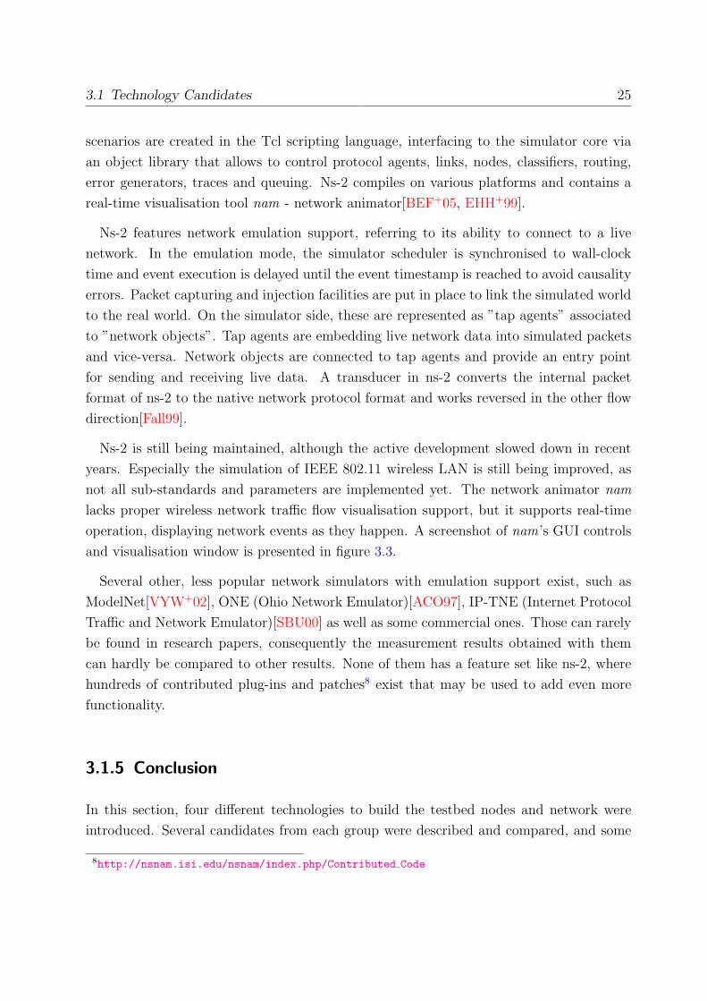
Ns-2 is still being maintained, although the active development slowed down in recent
years. Especially the simulation of IEEE 802.11 wireless LAN is still being improved, as
not all sub-standards and parameters are implemented yet. The network animator nam
lacks proper wireless network traffic flow visualisation support, but it supports real-time
operation, displaying network events as they happen. A screenshot of nam’s GUI controls
and visualisation window is presented in figure 3.3.
Several other, less popular network simulators with emulation support exist, such as
ModelNet[VYW+02], ONE (Ohio Network Emulator)[ACO97], IP-TNE (Internet Protocol
Traffic and Network Emulator)[SBU00] as well as some commercial ones. Those can rarely
be found in research papers, consequently the measurement results obtained with them
can hardly be compared to other results. None of them has a feature set like ns-2, where
hundreds of contributed plug-ins and patches8 exist that may be used to add even more
functionality.
3.1.5 Conclusion
In this section, four different technologies to build the testbed nodes and network were
introduced. Several candidates from each group were described and compared, and some
8http://nsnam.isi.edu/nsnam/index.php/Contributed Code

26 Chapter 3: Related Work
Figure 3.3: Nam: Visualising a Wireless Network (Screenshot)
approaches clearly outperformed others in terms of the testbed requirements set in the
previous chapter. In order to design our framework, the best technological approach and
implementation for the testbed network and nodes will be picked in this section, and the
verdict will be justified.
Testbed Network
The first thing to decide is whether to rely on real wireless network hardware or simu-
late/emulate the network properties in software. Real network hardware is expensive, the
acquisition costs are linear to the amount of nodes, while a simulated/emulated network
is usually limited to the cost of one computer. The hardware wireless network area size
is restricted by physical space limits, as a large network needs a large room. Simulat-
ed/emulated networks ideally do not take more space than a 19” rack. Also, real wireless
networks are possibly subject to unwanted third-party interference. An advantage of the

3.1 Technology Candidates 27
real network is the maximum possible realism, especially when it comes to wave propaga-
tion, which is too complex to be accurately recreated in software. But all other arguments
listed rule out the real network for our testbed.
This leaves us with simulation and emulation to create the wireless network. Simulation
clearly has the advantage that sophisticated simulators exist that can be used to create
complex topologies and support a wide range of technologies. On the other hand, network
emulators are generally easy to set up, and for simple experiments (such as links with
only a fixed delay) a simulator may be too laborious. Their performance is usually much
better as well, as they consist of a single entity where traffic is routed through instead of a
full-blown simulated network that needs to convert packages between the native network
and simulator format. Therefore, we decided to use both approaches, leaving the choice to
the user.
When it comes to network simulation, ns-2 is clearly the best candidate for our frame-
work. The requirements contain the aspect of comparability, and as many researches use
this simulator, the chance that results can be compared within the research community is
high. No other simulator is as widely accepted and provides a list of available extensions
quite as impressive as ns-2 does. Furthermore, ns-2 contains emulation support, which
gives us the flexibility to use any kind of nodes with it (simulated, emulated and real
ones).
For simple network emulation, the netem approach suits our requirements best. It
is already included in the Linux kernel, and the tools to control come with any Linux
distribution. It supports specifying a per-link delay, error rate, bandwidth, packet loss
and jitter, thus covering all the basic needs. In contrast to NIST-Net, it does not require
external code and is actively maintained. It can also be automated by scripts, while NIST-
Net relies on a GUI.
Testbed Nodes
Finally, we need to decide on a primary technique how to create the testbed nodes. The
choice of ns-2 as primary networking solution leaves all options open for consideration.
Real, emulated, simulated and virtualised nodes are all able to connect to it. Node em-
ulation is ruled out as it is inefficient and slow and only required for special cases. For
real hardware nodes the same restrictions as to the real network apply. Acquisition and
operation cost, space requirements and elaborate deployment (software installations) all

28 Chapter 3: Related Work
limit the scalability of this approach. Trace files are spread over many machines and need
to be retrieved for analysis. The chance of human error and hardware failure also increases
with the node count. Therefore, real nodes can be ruled out.
Node simulation requires protocols and applications to be implemented for the simula-
tor, thus delaying the release process. Measurement results may be less realistic, as the
applications do not run on the actual hardware. Running real-life applications on the
actual operating systems is certainly one of the most important prerequisites for protocol
development, therefore node simulation can be ruled out.
This leaves us with virtualisation. From the different virtualisation approaches, only
paravirtualisation provides the flexibility to run multiple instances of almost any operating
system completely isolated from others on a low resource footprint. Since more than s
hundred nodes may run on a single machine, this is the most cost-effective choice of all.
Also, automated control of these nodes is greatly simplified.
Beyond doubt, Xen is the most popular paravirtualisation platform of today. As Free
Software products are rare in this market and Xen outperforms most commercial solutions,
the decision for Xen is unambiguous. The support for upcoming CPUs with virtualisation
technology will even allow proprietary operating systems to run as guests under Xen. An
active community of users and developers gives us additional confidence in future for this
project.
3.2 Complete Solutions
After carefully evaluating testbed component options in the previous section, the decision
was made to build a complete wireless network testbed solution based on Xen for node
virtualisation, ns-2 for network simulation and optionally netfilter and netem for network
emulation. A complete solution integrates components for node and network creation in a
ready-to-run testbed package. To our best knowledge, no other complete testbed solution
based on Xen and ns-2 is available as of writing this thesis. There are, however, similar
projects using other techniques. A selection of the most interesting projects is introduced
below. Their benefits and drawbacks are outlined, and their potential as inspiration for our
testbed framework is evaluated. Finally, the competitors are compared to our approach
and tested for their compliance with our requirements in the conclusion.

3.2 Complete Solutions 29
3.2.1 Similar Projects
The projects introduced here can be used for network emulation, although not all of them
are wireless network testbeds. They only fulfil a subset of our requirements, but come close
enough to our goals to enable a comparison between them.
EINAR (EINAR is not a router)9 is a router emulator that is meant to teach students
about routing protocols. It can also be connected to physical routers that talk RIP,
OSPF, BGP or IS-IS. EINAR is based on a Debian GNU/Linux live CD and uses
Xen to virtualise nodes. A scenario creation tool is included to set up a number
of nodes running certain network protocols. The parameters of the network links
between the Xen domUs are configured using netfilter and netem (integrated in the
Linux kernel). EINAR is missing wireless network emulation and generally does not
support scripted network behaviour or mobility models. The network parameters
are fixed and can only manually be modified at runtime. There are no options for
visualisation or tracing. EINAR is Free Software and can provide us with some ideas
on how to handle a Xen live CD environment and a web-based scenario creation
toolkit in the future work.
MarNET (Marburg Network Emulator)10 is an emulation system consisting of a dis-
tributed topology enforcement software and the paravirtualisation solution Xen.
To introduce communication parameters like packet loss and message delay to the
network, NetShaper is used, a Linux device driver developed at the University of
Stuttgart. A topology manager configures the NetShaper software according to the
specified network topology to create the impression of a live wireless network. Next
to the testbed network, a second control network exists that may be used to remote
control applications on the domUs. In order to take advantage of MarNET’s trans-
parent routing framework, applications need to be modified. MarNET does, just like
EINAR, not provide support for advanced wireless networking scenarios, it rather
emulates some basic network parameters only. Mobility models and testbed scenar-
ios must be manually specified in a proprietary format. There are no visualisation
options included. The project does neither offer a thorough documentation of Mar-
NET’s features, nor a download link for the software, thus hampering the comparison
to other solutions.
9http://www.isk.kth.se/proj/einar/10http://ds.mathematik.uni-marburg.de/de/research/project.php?name=routing

30 Chapter 3: Related Work
MASSIVE (MANET Server Suite Incorporating Virtual Environments) is an emulation
environment using real hardware nodes and a virtual overlay testbed network. The
MASSIVE software must be installed on participating nodes running Linux. Using
Linux Vserver isolation technology, multiple MASSIVE servers may run on a single
machine, each of them representing a network node. Those ”slave” nodes are man-
aged by a ”master” which runs a comfortable administration GUI tool. This tool
configures the virtual testbed network between the nodes and also includes a visu-
alisation option and predefined mobility patterns. Mobility is emulated by filtering
IP traffic flow to and from the nodes. Besides binary link states (a link exists or
does not exist) no other network properties (such as delay, loss, error rate) can be
emulated. Linux Vserver does not allow different Linux kernels for the local guests,
therefore MASSIVE cannot be used to test routing protocols implemented as kernel
modules. The authors of MASSIVE do not provide a public download location for
their software[MBLD05]. The Vserver technology used here is generally inferior to
our Xen approach, although it is less resource consuming.
MobiEmu (Mobility Emulator)11 is a tool for emulating Mobile Ad-hoc Network (MANET)
environments with Linux-based nodes. It supports many mobility scenarios, even in
the ns-2 format, emulating the node mobility. UML is used to run multiple nodes
on a single hardware machine, thus hard limiting the possible amount of nodes per
computer. MobiEmu uses the same scenario files as the widely used ns-2 to calculate
the location of the virtual wireless nodes, and based on this information, disallows
communication between nodes which are out of range of each other using Linux net-
filter. Besides that, like MASSIVE, MobiEmu does not support the emulation of any
other network properties (such as delay, loss, error rate). A ”master” node controls
the ”slave” nodes via GUI and provides an integrated visualisation tool. MobiEmu
can be downloaded from the project’s website[ZL02]. The GUI interface to control
the testbed nodes is an interesting feature, although it is not on our requirements
list.
NEMAN (Network Emulator for Mobile Ad-Hoc Networks) is an emulation platform that
allows several applications to run in the same operating system context, only isolated
by bindings to different virtual network adapters. Processes run side-by-side in the
user space, therefore no node isolation or virtualisation is required. Each application
uses its own TUN/TAP device for network socket access. The links between those
11http://mobiemu.sourceforge.net/

3.2 Complete Solutions 31
devices are managed by a topology manager equipped with a GUI. Topology visu-
alisation is included in the manager, and the scenarios may be specified in the ns-2
format. A monitor channel provides permanent network access to the TUN/TAP
devices, regardless of the currently active topology. Routing protocols need to be
integrated in the NEMAN software or in the connected node applications, which is
not desirable. Problems may arise when the Linux scheduler affects the user-space
application performance negatively. NEMAN is not available to the public[PP05].
3.2.2 Conclusion
The testbed solutions presented in this section have many features in common with each
other and our proposed solution. EINAR and MarNET are the only existing testbed
projects that use Xen, this is due to Xen being a relatively new approach. In the following,
references to our requirements from chapter 2 are highlighted in bold font.
EINAR focuses on demonstrating router behaviour to students, and therefore lacks em-
ulation or simulation of network properties. It clearly misses our flexibility and realism
requirements and also lacks visualisation support. The live CD approach limits filesystem
write access, which may become a problem when collecting large trace files as specified in
the tracing requirement.
MarNET is apparently work in progress, and relies on a non-public emulation software
with a limited feature set. Generally, the unavailability of MarNET documentation and
code rules out the project as a competitor as it misses our licensing and flexibility
requirements. Furthermore, the proprietary scenario and protocol specification format
does not meet the comparability requirement.
MobiEmu uses UML to create virtual nodes, which can be considered as an outdated so-
lution since Xen is available. The resource requirements of UML are massive, and MobiEmu
lacks sophisticated network emulation. The scalability requirement is clearly missed, and
as using UML means relying on multiple machines for a medium sized testbed, physi-
cal space requirements and hardware costs are certainly higher compared to other
solutions. Furthermore, it is not flexible as no form of network property emulation or
simulation is supported.
MASSIVE relies on the Linux Vserver approach for node isolation, blocking the use
of routing protocols implemented as kernel modules and therefore misses our flexibility
32 Chapter 3: Related Work
requirement. It also lacks advanced network parameter emulation. As there is no public
download location, we assume it is not Free Software, missing our desired licensing scheme.
NEMAN has possibly the lowest resource overhead of all competing projects, as it does
not rely on full node isolation or virtualisation. Nodes are applications bound to virtual
network devices. Although this approach scales best, it severely limits the flexibility.
Protocols implemented at kernel level cannot be evaluated in NEMAN. It also lacks visu-
alisation and Free Software licensing.
A wireless network testbed that meets the requirements and/or combines the key tech-
nologies Xen and ns-2 does not exist at the time of writing this diploma thesis. This
combination is deemed best regarding our requirements and the drawbacks of existing so-
lutions. Consequently, such a testbed was designed and implemented in the course of this
thesis. Its design and implementation process is documented in the following chapter.
Chapter 4
Architecture and Implementation
This chapter introduces the design of the Kasuari framework and describes the imple-
mentation details. In the first section the architecture is illustrated, explaining how the
framework components interact and how they fulfil the requirements defined in chapter
2 (highlighted in bold font style). The second section details the components used and
depicts the process of their implementation and integration into the testbed. Compatibil-
ity and deployment issues are also discussed in this chapter. It concludes with a list of
open design and implementation issues that emerged in the course of building the Kasuari
framework.
4.1 Architecture
In this section the architecture of the testbed environment is illustrated and explained.
A general overview conveys the basic structure of the framework and its components.
The following sections then characterise each component in detail, assisted by several
illustrations.
4.1.1 Overview
The Kasuari framework is a self-contained wireless network testbed designed to run on
a single standard computer, not requiring any other physical node or network hardware.
It is meant to provide a flexible and scalable testbed environment for a wide range of
wireless networking scenarios, while easy to install and maintain. The testbed operation
flow is automated and controlled by various scripts that let different software components
33

34 Chapter 4: Architecture and Implementation
Host (dom0)
Network simulatortestbed network
Ethernet bridgecontrol network
Guest (domU)
Read-only guest filesystem image
cow fs
aodvd
dtnd
...
Guest (domU)
cow fs
aodvd
dtnd
...
Guest (domU)
cow fs
aodvd
dtnd
...
Guest (domU)
cow fs
aodvd
dtnd
...
ns-2 xenbr1
Figure 4.1: Architecture of the Kasuari Framework
interact with each other. The Kasuari framework is comprised of a set of programs, Linux
kernel images, a virtual machine monitor and a guest filesystem, all packaged for the
Debian/GNU Linux distribution. Alternatively, all components can be compiled from
source.
The testbed framework uses the Xen virtualisation software to create virtual testbed
nodes. It allows the nodes to be full Linux instances that run slightly modified, but in-
dependent kernels. The machine that hosts the testbed runs the host operating system
(dom0 ) on top of the Xen virtual machine monitor, also known as hypervisor. In figure 4.1,
the white box containing all components represents the hypervisor which is spawning the
host operating system (dom0 ) depicted in light blue and the guest instances (domU ) in
orange. While the host operating system can be any Linux installation which is compatible
with the Xen kernel and bears the Xen tools, the guest filesystem contains a pre-configured
Debian GNU/Linux installation that comes with the Kasuari framework. The guests may
run arbitrary combinations of testbed applications, kernel modules and routing configu-
rations. They all use the same Xen-enabled kernel, but each node runs an independent
instance of it and can therefore be configured and extended by kernel modules without
affecting other nodes. This increases the realism, as unmodified applications and kernel
modules may run on the testbed nodes as in a real-life scenario. Furthermore, the protocol

4.1 Architecture 35
implementations of the real operating system are used instead of a simulator implementa-
tion that possibly behaves differently. Xen also meets our requirements of low hardware
costs and low physical space usage as the nodes are virtual.
All guest nodes boot from the same read-only root filesystem image (the green box in
figure 4.1). In order to grant write access, a copy-on-write driver redirects write accesses
and stores modified files separately for each guest (the dark blue boxes in figure 4.1, for
further details see section 4.1.3). This way, concurrent write accesses to the guest filesystem
are avoided, while full ”virtual” write operations are granted.
Each guest node has two virtual network interfaces provided by Xen. The primary
interface is used to connect to the testbed network (the dotted lines in figure 4.1), the
secondary interface connects to the control network (the dashed lines). The testbed network
is simulated by the ns-2 network simulator running in real-time mode on the host system.
According to the currently loaded simulation script (that specifies the network topology),
ns-2 forwards, delays or drops ethernet frames between the guests, thus providing them
with a realistic impression of a wireless network. The links in the control network are
persistent and can therefore be used to contact the guest nodes at any point in time during
testbed operation and control them. They are interconnected by a Linux software bridge
named ”xenbr1” in figure 4.1. Instead of using ns-2 to simulate the testbed network, a bridge
can be used as well to allow the nodes to communicate over their primary network interface.
Linux netfilter rules and netem can then be used to emulate basic network properties such
as packet delay, loss and reordering. The primary choice for the testbed network remains to
be ns-2, as it allows for much more complex parameters and can recreate mobility patterns.
To analyse the network traffic that occurs in the testbed network, several tracing op-
tions are put in place. Ns-2 provides an extensive tracing facility where ethernet frame
information is recorded to a trace file. Furthermore, ns-2 can generate node movement
and traffic data for visualisation with nam (network animator), which is also included in
the Kasuari framework. The third option is tcpdump, a tool that runs on the host system
and is able to capture raw IP traffic from the virtual network interfaces of the guest nodes
to a file for further analysis. The file formats used are common in the network research
community and therefore allow for easy comparability.
Details of the networking, filesystems, tracing and control scripts in the Kasuari frame-
work are illustrated and explored in the following sections.

36 Chapter 4: Architecture and Implementation
Figure 4.2: Overview: Networking
4.1.2 Networking
Figure 4.2 illustrates the architecture of the testbed network (links and components have
dotted lines) and the control network (dashed lines). Xen is configured to assign two
network devices to each guest, one to connect to the testbed network and one for the
control network. The testbed network interfaces are named ”eth0” on the guest side and
”kasuariN .0” on the host side where N is the node number. The control network interface
names are ”eth1” and ”kasuariN .1”, respectively.
If ns-2 is used to simulate the testbed network, all virtual network devices that belong
to it are connected to the ns-2 process. Specific MAC addresses need to be assigned
to the virtual network interfaces, as ns-2 internally maps the interfaces to its simulation
nodes based on their layer-2 address. The rightmost hexadecimal value of the MAC address
indicates the node number, e.g. ”FE:FD:C0:A8:2F:XX” where XX is the node number+1

4.1 Architecture 37
in hexadecimal notation. This translation is necessary because ns-2 has an internal node
addressing scheme that is incompatible to Ethernet. Ns-2 is able to open raw sockets to the
virtual network interfaces and handles all occurring network traffic on the link layer, as the
interfaces are not connected to each other in any other way. The scenario specification files
use are in the common, flexible Tcl scripting language that may be used with any other
ns-2 simulation, hence it caters for the comparability requirement defined in chapter
2. Simulating the network in ns-2 also leads to a shielding from any unwanted outside
influences (such as radio interference), therefore a high control level is achieved and the
network behaviour is deterministic. Further details on ns-2 and the testbed network can
be found in section 4.2.2.
As the testbed applications usually do not communicate based on layer-2 addresses,
a scheme for guest IP address assignment exists in the Kasuari framework. Testbed
nodes (in the orange box in figure 4.2) are assigned the address 10.0.0.N , N being their
node number + 1. This scheme, just like the MAC addressing scheme, limits the number
of nodes in the testbed network to 254, which is not a problem as other constraints to the
maximum node count apply (see section 4.5).
Alternatively, ns-2 can be replaced by a software bridge that connects all network devices
of the testbed network to each other. Linux netfilter rules and the netem utility can then
be used to prevent or allow traffic flow on the network and link layer and introduce basic
network properties such as delay, loss and reordering. This does not allow for complex
mobility scenarios, but is easy to set up and configure and may be sufficient for basic
testing. It is not as flexible and realistic as ns-2, but scales very well and has a high
control level. Details and examples can be found in section 4.2.3.
Parallel to the testbed network, a control network is established to remotely control
applications on the testbed nodes from the host system during scenario execution. It
could also be used to transfer configuration files prior to testbed runs or log files after a
run. Furthermore, nodes can be configured to use this permanent link to the host system
as an Internet gateway route, presuming that the host is configured for NAT (Network
Address Translation) and bears an Internet uplink (via the host’s ”eth0” interface in figure
4.2). A Linux software bridge with the IP address 10.0.1.254 connects all guest control
network interfaces to the host system and to each other, allowing communication between
the nodes. Their IP addresses are 10.0.1.N , N being node number + 1. As they are in a
different subnet, the testbed network is not affected as long as correct routes are set on the
nodes and testbed applications only bind and connect using testbed interfaces.

38 Chapter 4: Architecture and Implementation
Xen maps the emulated network devices on the host side to the virtual adapters visible
on the guests using its integrated netback and netfront drivers. These drivers are part of
the Xen host and guest kernel.
4.1.3 Filesystems
The Kasuari framework allows to create multiple guest Linux instances all based on the
same (read-only) root filesystem image. Although it is possible to modify a Linux distri-
bution to boot from a read-only root filesystem, write access is usually desired to ensure
correct application behaviour and to enable run-time modifications to configuration and
log files. This way the guest system can run any regular Linux installation and applications
can run in their default configuration. Obviously, concurrent write access to the same root
filesystem from multiple guests is troublesome. Furthermore guests should not be able to
permanently modify their root filesystem, as it is often desired to restart the nodes with a
”clean” filesystem after a testbed run.
One solution to this problem is a technique called copy-on-write. Multiple virtual copy-
on-write block devices can be instantiated, all pointing to the same filesystem. Write
requests to the copy-on-write device are redirected to another location, i.e. an image file.
On read requests, this image file will be checked for modifications first. If the data to be
read has not been modified so far, the read request is forwarded to the read-only filesystem.
Figure 4.3 displays the correlation of host and guest filesystems in the Kasuari frame-
work and the copy-on-write layer between them. The host filesystem (blue box) contains
everything that is necessary to run both the host and guests in the Xen virtual machine
monitor. The dom0 and domU kernel images as well as the hypervisor binary are required
to boot the host and guest systems. The Xen utilities are needed to control and configure
the virtual machines, and a 32-bit or 64-bit installation of Debian GNU/Linux serves as
the system base. Furthermore, the host filesystem contains the default guest filesystem
image included in the Kasuari framework that is employed for each testbed node. This is
a slightly modified 32-bit Debian GNU/Linux unstable installation (for details see section
4.2.5).
As the testbed nodes are created, the testbed control scripts establish a virtual block
device for each guest using the cowloop copy-on-write driver. Write accesses are redirected
into newly created image files within the host filesystem. In figure 4.3 those are depicted on
the top left/right corners of the blue box and named /tmp/kasuari1 and /tmp/kasuari2,

4.1 Architecture 39
Figure 4.3: Overview: Filesystems
as only two guests are illustrated.
The copy-on-write block devices, named /dev/cow/0 and /dev/cow/1 in figure 4.3, are
presented as the root filesystem to the guests (orange boxes) by the Xen block device fron-
tend/backend driver. This driver is able to map any filesystem or block device accessible
on the dom0 to a virtual block device visible on the domUs (/dev/xvda1). This way, all
testbed nodes boot from the same read-only root filesystem, while all write accesses from
within them are redirected to isolated locations. After the testbed run, the copy-on-write
block devices can be mounted on arbitrary locations in the host filesystem in order to re-
trieve log files or other testbed data from them. This is possible as long as no modifications

40 Chapter 4: Architecture and Implementation
are made to the original root file system image.
4.1.4 Trace Files
In a wireless network testbed, detailed observation of all events that occur on the nodes and
in the network is crucial and needs to be recorded in order to find errors and optimisation
opportunities in the applications tested. The Kasuari framework features multiple tracing
methods as depicted in figure 4.4.
On the host (blue box), three tracing options exist where trace files are stored on the
host filesystem. Ns-2 is able to create packet and nam traces. The packet trace contains
detailed information about all wireless network events, such as time, node ID, packet type
and size as well as source and destination addresses. If packet types are identified, the trace
log may contain additional, protocol-specific information. The packet content (payload) is
not recorded. The nam trace format is intended for visualisation purposes and therefore
contains information related to the node location, velocity, size and colour. This data
can either be written to a file, or sent directly (”piped”) into a nam instance for real-time
visualisation. The ns-2 tracing options are set in the simulation script. In the default script
included in Kasuari framework, the packet and nam trace data is written to /dev/null,
where it is discarded. The user may change this line in the simulation script, supplying his
or her desired trace path and file name or pipe command.
To capture the full contents of each frame being sent in the testbed network, a third
method is adopted. The tcpdump tool is attached to the Xen virtual network devices,
recording all passing traffic to a file. Applications like Wireshark 1 can then be used to
display, filter and analyse the packet traces after the testbed run.
Finally, tracing may also be performed on the guest (the orange box in figure 4.4) itself.
Although it is desirable for simplicity to collect traces outside of the guest systems at a
common location in the host filesystem, it is usual that most testbed applications write
their log files to a folder somewhere in the guest filesystem. Due to the copy-on-write
devices that are employed in the guests, these log files can be written and they actually
reside in an image file on the host. After shutting down the testbed nodes, these image
files can be mounted on the host to access the application logs. Alternatively, they can be
retrieved using scp via the control network from the live guests.
1http://www.wireshark.org/

4.1 Architecture 41
Figure 4.4: Overview: Trace Files
The trace files that accumulate in the Kasuari framework are in well-know, established
formats and can therefore be analysed with common tools and compared to observations
from real-life networks or other network simulations. This fulfils our comparability re-
quirement listed in chapter 2. Also, the trace files can be used for visualisation.
4.1.5 Controlling the Testbed
In the previous sections, the architecture of the different parts of the testbed has been
detailed. For successful testbed scenario operation, a control authority must be established
that configures, starts and stops the testbed components on time. Furthermore, it should
allow to execute automated series of testbed runs that do not require user interaction. This

42 Chapter 4: Architecture and Implementation
is necessary to fulfil the automation requirement defined in chapter 2.
Several scripts are included in the Kasuari framework that control the testbed oper-
ation. The main scripts to create and destroy the testbed nodes are kas-create and
kas-destroy. The kas-create script takes the number of testbed nodes as an argument
and invokes the Xen utilities to create Kasuari framework nodes. The kas-destroy script
shuts down all running machines and resets the testbed to its original state. These scripts
invoke other scripts that bring up and remove copy-on-write block devices and virtual
network interfaces.
The kas-create and kas-destroy scripts can themselves be invoked from a master
script that controls the whole testing procedure. It creates the testbed nodes, starts the
packet capturing process and runs the simulation script in ns-2. After the simulation has
ended, the packet tracing is stopped and all machines are shut down. The copy-on-write
filesystems are set back to their original state after the log files they contain were gathered.
This is achieved by simply overwriting the existing copy-on-write images that contain the
changes made during the testbed run upon the next testbed startup.
To set parameters in the testbed nodes, the kas-create script passes kernel command
line parameters to the Xen guests. These parameters can be accessed from within the
guest’s proc file system (/proc/cmdline). Several startup scripts in the guest filesystem
image read those switches and launch and configure daemons accordingly. This way, IP
addresses are assigned to the network interfaces, routes are added to the kernel routing
table and the host name is set on startup.
Further scripts in the Kasuari framework include scripts for patching, compiling and
packaging of the Linux kernels. Implementation details of the main scripts can be found
in section 4.2.6.
4.2 Components
After explaining the architecture of the Kasuari framework, this section now provides de-
tails on the components used and scripts developed. The components are existing Free
Software projects used to build the testbed, while the scripts were developed in the course
of this thesis. Necessary modifications to the components are explained and more insight is
given on the inner workings of Xen, ns-2, netfilter/netem, the Debian GNU/Linux installa-
tion on the guests and the host system as well as the testbed control scripts. Furthermore,
4.2 Components 43
the process of creating the Debian packages that constitute the Kasuari framework is de-
tailed here.
4.2.1 Xen Virtual Machine Monitor
Xen consists of several parts: the virtual machine monitor (a bootable binary file also
known as the hypervisor), host and guest kernels and the Xen utilities. They are available
either as source code from the Xen repository2 or as pre-packaged binaries for several Linux
distributions. As the Kasuari framework integrates into Debian GNU/Linux, the Debian
packages of Xen were used to avoid additional dependencies. Everything that is necessary
to run Xen is available in the Debian unstable package repository.
The Debian packages xen-hypervisor-3.0-i386 and xen-hypervisor-3.0-amd64 con-
tain the 32-bit and 64-bit binaries of the Xen virtual machine manager 3.0, respectively.
Xen is only available for the X86 and X86 64 architectures. Having 64-bit support is bene-
ficial on systems with a large amount of memory, as a 32-bit machine can only address up
to 4 GB RAM directly. As each testbed node consumes a fixed amount of memory, more
than 4 GB RAM are necessary for large scenarios (200+ nodes) with memory-demanding
applications on the nodes. The hypervisor binary needs to be executed on boot. A sample
configuration file for Debian’s default boot loader (grub) is shown in listing 4.1. In the
kernel line, the hypervisor path and filename is specified. The module entries assign the
actual host kernel, root filesystem and initrd (initial RAM disk image, required for modular
kernels) to be booted as dom0.
Xen was designed to handle up to 100 guest machines. Pushing the number to 200+
requires a few modifications, as some resources may run out. First of all, more than 4 GB
RAM is necessary, as 250 guests with 32 MB memory each would require about 8 GB in
total, plus several hundred megabytes for the dom0. To address such an amount of memory
without workarounds, 64-bit platform hardware is advisable. Xen does not automatically
make use of system memory beyond 4 GB, therefore a boot option max addr=16G for 16
GB of memory should be passed to the hypervisor.
One example for limited kernel resources is the number of virtual IRQs. The more Xen
guest machines run, the more of these software interrupts are needed. Their maximum
number is defined in the file include/asm-x86 64/mach-xen/irq vectors.h in the Xen
2http://xenbits.xensource.com/xen-unstable.hg
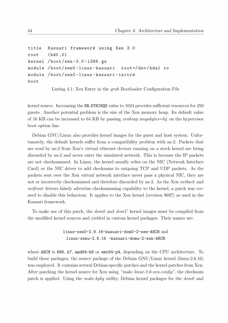
44 Chapter 4: Architecture and Implementation
title Kasuari framework using Xen 3.0
root (hd0 ,0)
kernel /boot/xen -3.0- i386.gz
module /boot/xen0 -linux -kasuari root=/dev/hda1 ro
module /boot/xen0 -linux -kasuari -initrd
boot
Listing 4.1: Xen Entry in the grub Bootloader Configuration File
kernel source. Increasing the NR DYNIRQS value to 1024 provides sufficient resources for 250
guests. Another potential problem is the size of the Xen memory heap. Its default value
of 16 KB can be increased to 64 KB by passing xenheap megabytes=64 on the hypervisor
boot option line.
Debian GNU/Linux also provides kernel images for the guest and host system. Unfor-
tunately, the default kernels suffer from a compatibility problem with ns-2. Packets that
are read by ns-2 from Xen’s virtual ethernet devices running on a stock kernel are being
discarded by ns-2 and never enter the simulated network. This is because the IP packets
are not checksummed. In Linux, the kernel usually relies on the NIC (Network Interface
Card) or the NIC driver to add checksums to outgoing TCP and UDP packets. As the
packets sent over the Xen virtual network interface never pass a physical NIC, they are
not or incorrectly checksummed and therefore discarded by ns-2. As the Xen netback and
netfront drivers falsely advertise checksumming capability to the kernel, a patch was cre-
ated to disable this behaviour. It applies to the Xen kernel (revision 9697) as used in the
Kasuari framework.
To make use of this patch, the dom0 and domU kernel images must be compiled from
the modified kernel sources and yielded in custom kernel packages. Their names are:
linux-xen0-2.6.16-kasuari-dom0-2-xen-ARCH and
linux-xenu-2.6.16 -kasuari-domu-2-xen-ARCH
where ARCH is 686, k7, amd64-k8 or emt64-p4, depending on the CPU architecture. To
build these packages, the source package of the Debian GNU/Linux kernel (linux-2.6.16)
was employed. It contains several Debian-specific patches and the kernel patches from Xen.
After patching the kernel source for Xen using ”make linux-2.6-xen-config”, the checksum
patch is applied. Using the make-kpkg utility, Debian kernel packages for the dom0 and

4.2 Components 45
domU are created. A custom kernel configuration is used which enables some additional
features required for the Kasuari framework, such as support for advanced netfilter rules,
netem and netlink/raw socket support. The whole build process is controlled by a large
bash script that creates two kernel images for each of the four supported CPU architectures
686, k7, amd64-k8 and emt64-p4. Building these eight kernel packages can take between
thirty minutes and several hours, depending on the performance and number of CPU cores
available on the build machine.
Next to the hypervisor package and the customised kernel packages, some extra packages
need to be installed in order to run Xen in the Kasuari framework. The xen-utils-3.0
package contains the python scripts to start, stop, configure and monitor the Xen machines.
The package bridge-utils provides the brctl tool to manage Linux ethernet bridges.
Finally, libc6-xen is a modified C library for Xen to improve the performance of certain
critical system calls, and is already installed in the guest filesystem image.
4.2.2 Ns-2 Network Simulator
The ns-2 network simulator is the preferred solution to simulate the wireless testbed net-
work in the Kasuari framework. The simulator itself is implemented in C++ and uses the
Tcl scripting language to specify the simulation parameters. A typical ns-2 script includes
wireless communication parameters (such as the radio propagation model used, the MAC
type, the interface queuing scheme and the antenna model), scenario parameters (such as
field size, simulation time and node count), the ns-2 routing protocol used and the trace
file location. These parameters are then used to create and set up the nodes accordingly.
Furthermore, an external mobility file is loaded in the simulation script. It contains Tcl
script commands to set the initial node locations in the grid and move the nodes at selected
timestamps during the simulation. These mobility files can be very large and detailed and
thus are rarely created by hand, but merely by software. Ns-2 includes the CMU scenario
generator setdest that is used exactly for this purpose. It is able to create random walk
node movement scripts, where the nodes move in randomly changing directions at a random
speed within a given range. This may not be the most realistic node behaviour for any
kind of scenario, but it can be a good starting point for most application testing situations.
Ns-2 can simulate basically any network topology as long as the corresponding mobility
file is supplied.
The Kasuari framework includes a sample ns-2 script (kasuari.tcl) with generic wire-

46 Chapter 4: Architecture and Implementation
less parameters (IEEE 802.11b, omnidirectional antenna and 250m maximum transmission
range), default trace file parameters for nam and ns-2 traces and the DumbAgent routing
protocol which basically disables routing. It also contains several functions to automat-
ically set up the nodes and bind them to Xen’s virtual network interfaces, thus running
the simulation in real-time (emulation) mode. As the mobility files are possibly large and
specific to the scenario settings (size, number of nodes, run time), they are not supplied
with the framework but can easily be generated on the command line prompt using the
setdest utility.
The official source code of ns-2 has emulation support built in since 1999[Fall99]. Emu-
lation support in this case means real-time simulation and a software hook to inject and
extract packets from and into the simulation network.
Originally, two interfaces to a real network were implemented in ns-2: Pcap network
objects and IP network objects. The Pcap method uses the Lawrence Berkeley National
Laboratory (LBNL) packet capture library (libpcap) to capture and inject link layer frames
on network interface devices in a promiscuous fashion. As this is a userspace implementa-
tion, the execution performance is low.
The IP network objects provide raw access to the local IP protocol, and allow the com-
plete specification of IP packets. The implementation makes use of raw sockets provided
by the kernel to send and receive packets at the network layer using any active interface.
Unfortunately, this method requires the IP configuration of the testbed nodes to be con-
sistent with the real nodes. Thus it is impossible to change node IP addresses during
the testbed run, e.g. using the Dynamic Host Configuration Protocol (DHCP) after the
network simulation has started.
Researchers at the University of Magdeburg forked the ns-2 version 2.29 source code
and included link layer raw socket support. This way, ethernet frames can be inserted to
and captured from the testbed nodes on the link layer. A tap agent for each node in the
simulation script handles traffic that goes in and out of the simulation, thus providing the
events in the discrete simulation. Each tap agent of the type ”Tap/Raw” is associated to a
network object, in this case called ”Network/Raw”, opening a link layer raw socket to the
node’s virtual network interface. These agent and object types were added to the Tcl/C
interface of ns-2 and can be used in simulation scripts, as shown in the script excerpt in
listing 4.2. In order to map the internal link layer addressing scheme of ns-2 to the MAC
addressing scheme in testbed network, the tap agents need to be made aware of the testbed
node’s MAC address assigned by the Xen node creation script. The address mapping is

4.2 Components 47
# create network object to access raw sockets at layer 2
set raw1 [new Network/Raw]
# open Xen virtual network device
$raw1 open kasuari1.0 readwrite
# create tap agent with kasuari1.0 ’s MAC address
set a1 [new Agent/Tap/Raw "FE:FD:C0:A8:2F:01"]
# assign network object to tap agent
$a1 network $raw1
# assign tap agent to ns-2 node
$ns attach-agent $node_ (1) $a1
Listing 4.2: Network Objects and Tap Agents in a ns-2 Simulation Script
then handled by ns-2.
As link layer raw sockets provide the most flexibility by being independent from the
network layer, and are integrated in the current Linux kernel code, this modified ns-2
version (dubbed in Magdeburg as nsemulation) is employed in the Kasuari framework.
It additionally contains enhancements to the emulation mode that increase the realism
and performance (scalability) of the testbed. A system call that reads the time from
the hardware clock has been replaced by a CPU cycle counter function, greatly reducing
the number of context switches necessary and increasing the accuracy of the virtual clock.
Furthermore, disk I/O is reduced by compressing log files in memory using the gzip library
before writing them to the hard drive[MI4].
Fortunately, the modified ns-2 has already been packaged for Debian GNU/Linux by the
authors. The nsemulation package is mirrored on the Kasuari framework HTTP/FTP
server for convenient installation. The latest version of the network animator nam (for
visualisation) and some libraries necessary are also included in the repository.
4.2.3 Netfilter and Netem
As an alternative to ns-2, the netfilter rules and the netem capabilities of the Linux kernel
can be used to introduce basic network properties to the virtual network devices. The
netfilter rules can be set by the iptables userspace tool, widely used to configure firewalls.
It can be used to drop or forward certain packets or frames passing the virtual network

48 Chapter 4: Architecture and Implementation
devices that are interconnected by a software bridge. Two different approaches can be em-
ployed: either drop all interface traffic and then allow certain protocols, source/destination
IP/MAC addresses or interfaces (as in listing 5.1), or allow everything and disallow only
specific properties. As these rules can be dynamically altered by scripts during the testbed
operation, a simple impression of node mobility can be achieved by blocking communication
between nodes that are outside of each others transmission range.
More sophisticated properties than just link breaks can be introduced into the testbed
network using the netem functionality of the Linux kernel. The tc program from the
iproute2 package can be used to assign queuing disciplines to the virtual network inter-
faces. A queuing discipline has an input and an output queue and decides which packets
to send at what time based on the current settings. In the current version of netem, only
outgoing traffic is shaped. Supported shaping parameters include packet delay, loss, dupli-
cation, reordering and rate control per interface[Hem05]. The netem settings can as well be
dynamically altered during testbed operation, e.g. to increase delay and loss and decrease
the data rate when the distance between two nodes grows. This provides a more realistic
impression of mobility than using netfilter alone. The netem properties can be controlled
via scripts, but currently no solution exists to generate such scripts based upon a math-
ematical mobility model. Details on the tc syntax used to set up the queuing disciplines
can be found on the netem wiki page3.
The netfilter and netem features are already part of the kernel used in the Kasuari
framework, and the necessary userspace tools to control them are included in every Linux
distribution. Therefore, no extra software packages need to be created in order to enable
these network properties. Only a simple netfilter rule set script (netfilter.sh, shown in
listing 5.1) is included in the framework for demonstration purposes, as we primarily rely
on ns-2 for the testbed network operation.
4.2.4 Copy-On-Write Block Device Driver
Several solutions to create copy-on-write block devices in Linux exist. In this section, a
copy-on-write driver for the Kasuari framework is picked from a selection of promising
solutions and its integration and packaging is described.
A copy-on-write driver named blktap was recently added to Xen itself. It is fully inte-
3http://linux-net.osdl.org/index.php/Netem
4.2 Components 49
grated in the Xen 3.0 unstable branch and does not require the installation of additional
software. Blktap is a block tap device driver used to assign qcow copy-on-write image files
or drives to Xen guests. The qcow file format is taken from the copy-on-write implemen-
tation in the QEMU emulator project4. Xen includes a tool to create the qcow files from
existing filesystem images or new, empty qcow files. Unfortunately, blktap proved itself
to be rather unstable and suffers from bad performance, as it is in an early development
stage. It also occasionally crashes the kernel, greatly reducing the overall system stability.
Another method to create copy-on-write block devices is the Logical Volume Manager
(LVM) which is integrated in Linux. This method is also directly supported by Xen.
Unfortunately, the LVM implementation is flawed as well. In our tests it was impossible to
create more than 30 copy-on-write LVM devices running simultaneously. Furthermore, the
filesystems on the LVM devices cannot grow dynamically upon writing, leading to error
messages and data loss when the original filesystem size is exceeded.
UnionFS 5 can also be used to create a filesystem with copy-on-write properties, but it
also suffers from frequent crashes and low performance. According to the developers, it is
not recommended for production use yet.
Finally, cowloop6 is a Linux kernel module that provides file- or device-backed copy-on-
write block devices. The cowloop driver shields the block device driver or file below it from
any write accesses. Instead, it diverts all write-accesses to an arbitrary sparse file (cowfile).
A sparse file is a special type of file. It allocates a certain amount of disk space, but does
not completely fill it. It may contain ”holes”, and these holes do not actually consume disk
space. A modified block is written in this file area at the same offset as the corresponding
block in the read-only file. The sparse files can grow dynamically when necessary.
The cowloop kernel module and the accompanying utilities to create and manage the
copy-on-write devices and their back-end files proved themselves to be stable and high-
performance and were therefore chosen for the Kasuari framework. There are some con-
currency issues when accessing the copy-on-write control device (/dev/cow/ctl) that may
lead to a kernel panic, but can be avoided by creating and destroying the copy-on-write
devices sequentially instead of concurrently. Initially, the cowloop module had a kernel
memory allocation issue that did not allow for more than 114 copy-on-write devices at the
same time. After contacting the developers, we received an updated version that increased
4http://www.qemu.com/5http://www.am-utils.org/project-unionfs.html6http://www.atconsultancy.nl/cowloop/
50 Chapter 4: Architecture and Implementation
this number to 254.
Two Debian packages were created to incorporate the cowloop kernel module and the
copy-on-write management utilities (cowdev, cowsync, cowlist, cowrepair and cowmerge)
into the Kasuari framework. The cowdev utility is needed to create and delete the virtual
block devices. It is used in the control scripts that create the testbed nodes. The other
utilities perform miscellaneous cowfile administration tasks such as synching the module
memory content to the cowfile on the disk or merge the changes made to the cowfile back
to the back-end filesystem. These tools are not used in the testbed scripts, but may be
required for advanced cowfile handling by the user.
The copy-on-write devices in the Linux device file system (/dev/cow/N, where N is the
device number) are dynamically created by the udev daemon in Debian GNU/Linux, which
is configured accordingly upon package installation. The cowloop software is licensed under
the terms of the GNU General Public License (GPL) version 2 and the packages we created
are available from our HTTP/FTP server.
4.2.5 Debian GNU/Linux Operating System
The choice for Debian GNU/Linux as the Kasuari framework base Linux distribution
was straightforward: Debian GNU/Linux is in widespread use and known as a reliable
distribution for more than a decade. It has a large user community and is renowned for
its thought-out package management system. Debian GNU/Linux unstable is used in the
testbed, which is indeed quite stable and always contains the latest software versions.
Although Debian GNU/Linux is the preferred operating system for the host system
and the testbed nodes, the Kasuari framework is flexible and does not depend on it.
All components can as well run on any other Linux distribution, as their source code is
publicly available. On the host system, the Debian packages of Xen are used, simplifying
and accelerating the installation process, as building and installing Xen from the source
code is rather elaborate. The guest system is a pre-configured Debian GNU/Linux unstable
installation in a filesystem image. As it is a minimal installation, it only contains some
basic GNU command line utilities. Thus, the whole system only uses about 200 megabytes
of a 250 megabyte image file. It does not contain any kernel images, as they reside in the
host filesystem. Kernel modules, though, need to be stored within the guest image in order
to load and unload them at runtime.

4.2 Components 51
In addition to the basic default packages installed on the guest, a few extra utilities
are present: the GNU debugger and C/C++ compiler for quick software compiling and
debugging directly on the guest, OpenSSH for secure remote shell and file access over the
control network as well as the Emacs-like editor jed. Additional packages can be installed
in the guest (by mounting it on the host and using the chroot command on the mount
point) as long as there is free space left in the image file. The image file size is not fixed,
it can be enlarged or shrunk using the ext3 filesystem utilities.
The configuration file of the init process on the guest has been modified to disable the
login prompt on the Xen console, as it can only be accessed from a privileged user on the
host anyway. For SSH connections, public key authentication can be used. These methods
save the user from typing the username and password repeatedly when maintaining the
nodes during testbed operation.
Debian GNU/Linux is pure Free Software and can be obtained from one of the Debian
mirrors around the world7. Free Software meets our requirements of low operation costs
and no licensing troubles.
4.2.6 Testbed Control Scripts
To control the testbed operation, several bash and python scripts were developed exclusively
for thesis. The kas-create bash script loads the cowloop module, creates the bridge xenbr1
for the control network, boots the testbed nodes and verifies that they boot up correctly.
The nodes are started in a loop block where the xm create python script included in Xen
is called with the parameters vmid (guest node number), vmcount (total number of guests)
and vmname (base name of the guests, e.g. kasuari). To shut down the nodes after the
tests are completed, the kas-destroy script uses xm shutdown in a similar loop. Both
loops include a sleep statement (two seconds), as the cowloop module is sensitive to the
concurrent creation and destruction of copy-on-write block devices.
The testbed node configuration used by xm create is defined in the python script
/etc/xen/kasuari.cfg, where basic parameters such as kernel image file, memory size,
root file system location and network interfaces are specified. A snippet from a sample
configuration file is shown in listing 4.3. The ”extra” entry is the command line passed
to the kernel. It contains the host name and number as well as the network interface IP
7http://www.debian.org/mirror/list

52 Chapter 4: Architecture and Implementation
kernel = "/boot/xenu -linux -kasuari"
memory = 32
root = "/dev/xvda1 ro"
disk = [ ’cowloop :/home/kasuari/kasuari.img /tmp ,xvda1 ,w’ ]
name = "%s%d" % (vmname , vmid)
extra = "eth0 =10.0.0.%d ,255.255.255.0 eth1 =10.0.1.%d ,255.255.255.0
gateway =10.0.1.254 vmname =%s vmnr=%d" % (vmid , vmid , vmname , vmid)
vif = [ ’vifname =%s%d.0,script=vif -kasuari ,mac=FE:FD:C0:A8:2F:%x’
% (vmname , vmid , vmid),
’vifname =%s%d.1,script=vif -bridge ,bridge=xenbr1 ’
% (vmname , vmid) ]
Listing 4.3: Sample kasuari.cfg (excerpt)
configuration that is applied by the guest systems on bootup. Startup scripts on the guests
parse the kernel command line and interpret the parameters accordingly. In listing 4.4,
an excerpt of a domU startup script is shown, where the host name of the guest is set to
XY where X is vmname (e.g. kasuari) and Y is vmid. These values were passed to the
kernel command line by the configuration script, which got its parameters from invoking
xm create in the kas-create script accordingly.
The ”vif” entry in listing 4.3 configures the two virtual network devices created by Xen.
The first interface is assigned a specific MAC address (required for ns-2) and the script
vif-kasuari is used to configure the interface on the host side. As no host configuration
of this interface is desired, vif-kasuari is a placeholder script that does not touch the
interface settings. The second virtual network interface gets attached to the control network
bridge xenbr1. The attaching is handled by the vif-bridge script that is included in Xen.
The ”disk” entry in listing 4.3 defines the block device containing the root filesystem
that will be accessible from the guest. The ”cowloop:” prefix specifies the type of the
block device, in this case a copy-on-write drive using the cowloop module. The path and
filename is the location of the read-only guest filesystem image, followed by the directory
where the copy-on-write image (cowfile) is created (/tmp in this case). Moreover, ”xvda1”
specifies the name of the block device as it appears in the guest, and ”w” just tells Xen
that this device is writable.
As the cowloop driver is unknown to Xen, a handler script (block-cowloop) for the

4.2 Components 53
HOSTNAME=domU
# Set hostname from kernel parameter
for word in $(cat /proc/cmdline) ; do
case $word in
vmname =*)
HOSTNAME=‘echo $word | /usr/bin/cut -d = -f 2‘
;;
esac
done
for word in $(cat /proc/cmdline) ; do
case $word in
vmid =*)
HOSTNAME=$HOSTNAME ‘echo $word | /usr/bin/cut -d = -f 2‘
;;
esac
done
echo $HOSTNAME > /var/www/hostname.inc
log_action_begin_msg "Setting hostname to ’$HOSTNAME ’"
hostname "$HOSTNAME"
log_action_end_msg $?
Listing 4.4: Startup Script to set domU Host Name (excerpt)
”cowloop:” prefix had to be created. It calls two other scripts, create cowloop and
destroy cowloop. These scripts interpret the parameters from the ”disk” entry in listing
4.3 and create or destroy the copy-on-write devices accordingly using the cowloop utilities.
A master script may be used to enable fully automated series of testbed runs. As it
is highly dependant on the testbed setup and the type of measurements required, it is
advisable for the user to create his or her own master script for each testbed configuration.
Listing 4.5 contains an example master script that accepts the testbed width and height
(X and Y ) as parameters and runs the ns-2 scenario in kasuari.tcl five times in a row
with 10, 20, 40, 80 and 160 nodes after creating the necessary amount of Xen guests. The
corresponding mobility files with the correct field dimensions and number of nodes must be

54 Chapter 4: Architecture and Implementation
if [ ! ${1//[^0 -9]} ] || [ ! ${2//[^0 -9]} ]; then
echo "Usage: auto.sh <field width (x)> <field height (y)>"
exit 1
fi
for $nodes in 10 20 40 80 160
do
kas -create $nodes
for ((a=1; a <= $nodes ; a++))
do
tcpdump -s 0 -i kasuari$a .0 \
-w dumps/kasuari.dtn.${nodes}n.300s.$a.dump &
done
sleep 30
cat kasuari.tcl | sed -e s/%%%x%%%/$2/g \
| sed -e s/%%%y%%%/$3/g | sed -e s/%%% nodes %%%/ $nodes/g \
> kasuari -$2x$3 -$nodesn.tcl
nse kasuari -$2x$3 -$nodesn.tcl
killall tcpdump
kas -destroy
done
Listing 4.5: Testbed Master Script Example (auto.sh)
created prior to using this script. After booting the correct number of Xen machines with
kas-create $nodes, a tcpdump process for each virtual interface is created to capture all
traffic in the testbed network. The sleep statement causes the script operation to pause
for 30 seconds in order to wait for the tcpdump processes to start. Next, a copy of the
simulation script is made where the number of nodes and the field dimension placeholders
are replaced by the actual values for the current testbed run. This script is then run in ns-2
and terminates after the simulation time specified in it has passed. When the simulation is
over, all tcpdump processes are killed and the Xen guests are shut down. The next testbed
run begins immediately after the last Xen guest finishes.
The simple master script presented in listing 4.5 is a skeleton that is meant to be extended
by the user. It can be modified to run large sets of simulations where no one, but many

4.3 Compatibility 55
parameters change in the course of testing. Also, additional tracing and trace processing
may be implemented, e.g. merging the captured packet traces from each interface into one
file and filtering out unwanted traffic. The timing settings may also require adjustment to
the actual hardware performance.
4.3 Compatibility
The Kasuari framework inherits some restrictions on the hardware it runs on from the
Xen virtualisation software used. As of writing this thesis, Xen only supports the X86
and X86 64 CPU architecture and requires Linux as the host operating system. Other
platforms are currently not supported and this most likely won’t change in the near future.
As only these two, closely related CPU architectures are supported, Xen is highly optimised
for them and supports the features of their latest instalments such as built-in virtualisation
support (known as Vanderpool (Intel) or Pacifica (AMD) technology).
Although Xen itself does not consume lots of hardware resources, a machine which is
supposed to handle hundreds of virtual nodes that may access the CPU, the memory and
the hard drives concurrently, a multi-socket, multi-core CPU platform with plenty of RAM
(4 GB+) and hard drives in a RAID array is advisable as the testbed host system. If no
more than 80 nodes are required, a single-core AMD 3200+ machine with 3 GB RAM and
a single IDE disk drive is sufficient as proved in a tests.
The recommended operating system to run the Kasuari framework is Debian GNU/Linux,
although all components can be installed from source on any other Linux distribution. Bi-
nary packages are currently only available for Debian unstable. Besides Linux, no other
operating systems are supported for neither the testbed nodes nor the host system, as the
whole testbed architecture is bound to Linux paradigms.
4.4 Deployment
As mentioned in the previous sections, all components of the Kasuari framework are avail-
able as Debian packages. All packages are currently hosted on a public HTTP/FTP server,
which significantly reduces the installation and upgrading effort, thus meeting our low
testbed setup effort requirement.

56 Chapter 4: Architecture and Implementation
There are two Debian package repositories available, containing everything that is nec-
essary to install the Kasuari framework on 32-bit (i386) and 64-bit (amd64) Debian
GNU/Linux unstable installations. Only the guest filesystem image is not packaged and
needs to be downloaded from a separate location on the server. One repository contains
the Xen kernel images, the AODV-DTN (see chapter 5) and cowloop kernel modules, their
userspace utilities and the Kasuari framework control scripts. The other package reposi-
tory is a mirror of the nsemulation repository8. Details on the installation process can be
found in appendix A.
4.5 Open Issues
In this section, open issues in the design and implementation of the Kasuari framework are
discussed. They are explained in detail and pointers to possible solutions are given where
applicable.
Currently, the number of testbed nodes is limited by several restrictions. The cowloop
driver supports a maximum of 254 concurrent copy-on-write devices. Xen does not have
a hard limit for the amount of possible domUs, but occasionally becomes unstable and
slow at numbers beyond 200. The maximum node count we achieved in our tests was
254 nodes on a dual-CPU dual-core Intel Xeon machine with 16 GB RAM. To overcome
this limitation, a different copy-on-write driver as well as a different virtualisation solution
needs to be found. Moreover, more than 254 nodes on a single machine is not feasible
with today’s virtualisation software on reasonably priced computer hardware, therefore
one may look for a suitable distributed computing solution to spread the workload over
several machines. Scalability is one of the requirements we’ve defined in chapter 2 and
Xen and cowloop do scale very well on standard hardware, but they do not scale without
any limits.
Presently, all testbed nodes boot from the same root filesystem. In some cases it may
be required to run different Linux distributions in one testbed, e.g. to determine differ-
ences between the installations. Different root file systems in one testbed are currently
not supported by the control scripts that create and destroy the copy-on-write devices. It
is, however, possible to dynamically configure the nodes upon bootup by either specifying
kernel command line options that can be interpreted by boot scripts or by storing differ-
8http://bode.cs.uni-magdeburg.de/∼aherms/debian/

4.5 Open Issues 57
ent configuration files in the node file system and loading the appropriate configuration
according to the guest node identification. Generally it is desired to be able to compare
packet traces and log files between the nodes (comparability), therefore it is advisable
that every node runs the same operating system configuration.
When testbed nodes are shut down and restarted, they start off with a clean root filesys-
tem unaffected by previous test runs. To preserve the changes made to the copy-on-write
device by the guests, the modified files either need to be retrieved from the guests via the
control network at runtime or by mounting the copy-on-write device on the host after the
guest has shut down. The current implementation does not automatically keep the changes
but discards them on the next testbed run by overwriting the cowfiles. Users should modify
their master script accordingly if they want to save interesting data (e.g. log files) to a
safe location between automated testbed runs.
The IEEE 802.11 wireless networking standard9 allows for a higher Maximum Trans-
mission Unit (MTU) size in the wireless LAN than the typical 1500 bytes used in most
Ethernets. To maximise the realism of a wireless network scenario it is desirable to set
the MTU accordingly to allow larger frame sizes. Ns-2 supports this, but currently the
Xen virtual network devices do not. Their maximum MTU value is fixed at 1500 bytes. It
might be eligible to patch the Xen kernel sources in order to resolve this issue.
The Xen Debian packages are under constant revision by their maintainers. As the
Debian package installation of the Kasuari framework depends on them to build the domU
and dom0 kernels and provide the hypervisor and Xen utilities on the host, any changes
to these packages may break the installation procedure. Kernel patches may need to be
re-fitted to new kernel source releases, package dependencies need to be updated upon
package name changes and kernel packages need to be re-compiled when a new hypervisor
is installed. In every Linux distribution, software packages need constant maintenance
to keep up with the changes in other packages they depend on. This also applies to the
Debian packages of the Kasuari framework. As a fall-back solution for unexpected changes
to the official Debian Xen packages, a copy of the latest Xen packages that are known to
work is kept on our HTTP/FTP server.
Theoretically, another issue may arise that concerns the effects of insufficient hardware
resources on the testbed operation. When the machine running the Kasuari framework
operates a large amount of testbed nodes, there might not be enough free CPU cycles to
9http://standards.ieee.org/getieee802/802.11.html

58 Chapter 4: Architecture and Implementation
execute every operation in a timely manner. Furthermore, disk swapping due to insufficient
memory and concurrent disk access from the nodes may lead to heavy I/O load that affects
the overall processing performance. As a result, application on the Xen machines may run
slower than usual and ns-2, a userspace application, may not receive enough time slots
from the scheduler as necessary to process network traffic in real-time. This might occur
in a series of testbed runs, where only the runs with a high node count are affected.
This problem is purely theoretical, as we never experienced these issues on our high-
performance development machine (8 logical CPUs, 16GB of RAM). In a separate test to
analyse this problem with artificial high load on the nodes, ns-2 displayed some error mes-
sages on the command prompt indicating that real-time events could not be executed on
the scheduled timestamp. If these messages occur during normal Kasuari framework oper-
ation, it must be assumed that the measurement results and therefore the determinism
is affected.
A possible solution for ns-2 would be to decrease the niceness of the ns-2 process. Also,
the nsemulation package we use provides some performance enhancements that may help
to reduce this issue as well. Instead of costly system clock accesses to retrieve the time,
it implements an independent software clock for the emulation mode. It is also able to
compress trace files in memory before writing them to the hard drive, reducing the amount
of I/O instructions. Generally it is a good idea to use a computer with sufficient hardware
resources such as multiple CPUs and watching the output of ns-2 and Xen closely for
messages that may indicate performance problems.
Apart from these issues and limitations, the architecture of the Kasuari framework fulfils
the requirements defined in chapter 2. Even though not all the details listed in the require-
ments (such as the different wireless transmission technologies or the various mobility
models) have been implemented in the example scripts included in the Kasuari framework,
they are basically supported by ns-2 and its extensions. The scripts can be modified by
the user to fit these scenarios. The important flexibility requirement implies that as little
restrictions as possible should apply to what can be done with the framework.
The implementation performs as expected with only minor hiccups. It shows some of
the deficiencies of Xen, which clearly wasn’t build for such large node counts. The Xen
tools eventually slow down when maintaining the nodes. Apart from that, the Kasuari
framework runs quite stable and, if run on quality hardware, can survive overnight series
of continuos measurements without crashes. Some of the testbed components needed to
be modified to interoperate with others, but generally work very well together.

Chapter 5
Application: Extending AODV with
DTN
In this chapter what is presented is a typical usage scenario for the Kasuari framework:
a routing protocol implementation is extended and performance tested on virtual Linux
nodes in a simulated testbed network. Firstly it is necessary to explain the background on
this project and its technical details based on a recent paper publication[OKD06]. Then
we will show how the Kasuari framework is set up as testing platform and how it is used
in the development process, and finally we will present the results of the measurements
obtained in the testbed to illustrate the additional overhead and the increased message
delivery rate caused by the protocol extension.
5.1 Integrating DTN and MANET Routing
In a remote area without wired or wireless network infrastructure, mobile Ad-hoc Net-
work (MANET) routing protocols can be utilised to establish end-to-end paths across
communication nodes in a sparsely populated network. The nodes do not need an ini-
tial configuration as they can detect each other dynamically and recalculate their routing
tables when necessary, based on the information they exchange with each other. Due to
the varying node density and movement patterns in a dynamic networking environment,
an end-to-end path may not exist or may not sustain long enough to allow protocol in-
teractions to complete. However, the most dominant Internet transport protocol used in
consumer communication devices, TCP, does yield poor performance across an increasing
number of wireless hops[PWWM05] as these paths become less reliable at increasing hop
59

60 Chapter 5: Application: Extending AODV with DTN
count. In actual fact, most ”conversational” Internet protocols require an end-to-end path
to function properly as synchronous messages are exchanged. They are built on the as-
sumption that such a path exists and that it has a low packet drop rate and a non-excessive
round-trip time[Fall03].
In the following subsections we present a hybrid scheme that combines a MANET routing
protocol with routing in the Delay Tolerant Networking (DTN) architecture. DTN operates
as an overlay above the network transport layer and allows for asynchronous communication
in the form of message bundles (see subsection 5.1.2). As no end-to-end path is required
in this store-and-forward approach, an additional routing scheme is needed to forward the
bundles into the right direction. Input for this DTN routing can be extracted from and
conveyed by the MANET routing protocol.
The hybrid approach allows us to keep the advantage of maintaining end-to-end se-
mantics whenever possible while, at the same time, also offering asynchronous DTN-
based communication with no need for end-to-end connectivity. The routing protocol
is modified to spread information about DTN-capable nodes in order to improve DTN
performance[OKD06].
5.1.1 Ad-Hoc On Demand Distance Vector Routing (AODV)
At the time of writing this thesis, the Wikipedia article ”Ad hoc routing protocol list”1
contains 91 entries. They can roughly be divided into proactive, reactive, hierarchical,
geographic, multicast and power-aware. In a sparse and highly dynamic network, proactive
routing protocols are unsuitable, as nodes constantly communicate striving to maintain
a current routing table with routes to as many peers as possible. As most routes are
invalidated due to topology changes soon after they have been found, proactive routing
produces high volumes of unnecessary traffic. Hierarchical routing can also be ruled out as
structuring the few reachable nodes into a hierarchy seems redundant. Multicasting (one-
to-many packet dissemination, mostly used for media streaming) and power-awareness (e.g.
using battery states as routing metric) are not the focus of this work and thus irrelevant.
Geographic routing obviously requires the nodes to be aware of their location, which we
do not assume them to be, and therefore will not function. This leaves us with reactive
routing, where route searches are induced on demand and routes are kept only for the time
they are used. Low maintenance and overhead while still being able to quickly adapt to
1http://en.wikipedia.org/wiki/Ad hoc routing protocol list

5.1 Integrating DTN and MANET Routing 61
topology changes makes reactive routing protocols a good choice in a sparse MANET.
For our project we chose Ad-Hoc On Demand Distance Vector Routing (AODV), a
well documented[PBD03] reactive MANET routing protocol. A reactive routing protocol
is suitable for sparse networks with heavy node movement, as the protocol does not try
to constantly maintain a complete network topology table. AODV features on-demand
route discovery and maintenance to quickly adapt to dynamic link conditions and to keep
the network utilisation low. It determines unicast routes within the wireless network.
If a link breaks, all affected nodes are notified to alter their routing tables accordingly.
AODV is designed to handle almost any amount of data traffic and any node mobility
rate in populations from tens to thousands of mobile nodes and resultantly provides much
flexibility for various scenarios discussed in this section.
AODV defines three message types: Route Requests (RREQs), Route Replies (RREPs),
and Route Errors (RERRs). They are sent as regular UDP/IP packets, using the senders IP
address as originator IP address. Broadcast messages are sent to the IP limited broadcast
address (255.255.255.255). As long as the destination can be reached using existing IP
routes, AODV does not play any role. If an application tries to contact a host whose IP
address is not covered by the routing table, the node broadcasts a RREQ using expanding
ring search (increasing the IP time-to-live (TTL) step-by-step) to limit the network traffic
incurred. As soon as the RREQ either reaches the destination node or an intermediate
node with a recent route to the destination, a RREP is unicasted back to the originator. It
travels back along the same path the RREQ came on, as each intermediate node cached the
route back to the RREQ originator. If no route to the destination can be found, RREQs
are silently discarded and the route search is declared failed after a timeout.
While data is transferred over active routes, each node monitors the link states to its
direct neighbours. If a link breaks, a RERR message is sent to all direct neighbours
that may use this node as a next hop to reach a certain destination, causing the affected
neighbours to alter their routing tables accordingly. Shortly after the traffic flow stops
routes expire automatically.
AODV can be modified to distribute information about adjacent DTN routers and pro-
vides the necessary hooks (AODV extensions) to add our modifications. There are many
AODV implementations available (Wikipedia1 lists ten) to aid in the earliest stages and
provide an existing basis. AODV-UU2 from Uppsala University was selected as it runs on
2http://core.it.uu.se/adhoc/AodvUUImpl
62 Chapter 5: Application: Extending AODV with DTN
our Kasuari framework nodes (GNU/Linux kernel 2.6), has well-documented source code
and is feature-complete (RFC 3561[PBD03] compliant).
5.1.2 Delay Tolerant Networking (DTN)
Delay Tolerant Networking (DTN) is meant to address the issue of frequent network par-
titions leading to disruptive connectivity. The focus will be on the DTN architecture as
developed in the DTN Research Group (DTNRG)3 of the Internet Research Task Force
(IRTF)4. It operates as an overlay (bundle layer) above the existing network transport
layer and provides services such as in-network data storage and retransmission to allow for
asynchronous communication in a challenged network. Challenged networks typically suf-
fer from high latency, limited bandwidth, transmission errors and short-lived paths[Fall03].
Instead of transmitting small packets end-to-end, DTN routers forward arbitrary size mes-
sage bundles across one or more hops, while acknowledgements are optional. These bundles
are stored in the DTN router and forwarded as soon as a routing decision has been made.
Some DTN routers may have persistent storage (such as a hard disk) to hold messages
indefinitely. This allows for communication even though links are unavailable for a longer
duration.
To route bundles to their destination, endpoint identifiers (EIDs) are used to identify
receivers and applications. They are variable-length strings in the URI format[BFM05]
used to refer to nodes that send, receive, or forward bundles. An EID may refer to one
or more nodes, and an individual node may have more than one EID. Their format is
scheme:specific-address, where scheme is the scope in which specific-address is defined.
One routing algorithm often used in MANET-based DTNs is epidemic routing [VB00]:
messages are replicated and sent via all available links to maximise delivery probability
and minimise transmission time. The network is flooded with copies of a DTN bundle,
while duplicate bundles are discarded by the DTN routers. This procedure is not very
efficient when it comes to processing power requirements and network utilisation, but in
sparse networks the benefits of a high delivery rate far outweigh the negative effects of the
exceptional resource usage.
To conduct our measurements we chose to use the most recent version (subversion trunk)
3http://www.dtnrg.org4http://www.irtf.org

5.1 Integrating DTN and MANET Routing 63
of the DTN reference implementation5 as it conforms with the latest version of the bundle
protocol as specified in the Bundle Protocol Internet Draft[SB06] and runs on our desired
target platform (GNU/Linux 32-bit). Therefore it enables the most comprehensive analysis
available which complements our needs.
5.1.3 Combining AODV and DTN
Existing protocols that rely on an end-to-end path to allow for communication may yield
poor performance in a MANET environment, while other protocols may exclusively use
asynchronous store-and-forward message exchange and therefore need specific applications
designed to handle the possible delays and the asynchronous scheme. By combining AODV
routing with the DTN architecture, we can not only improve communication in sparse
wireless networks by adding a second communication option, but we can also improve
DTN performance itself. Applications can dynamically choose between an end-to-end
transmission (using one or more hops, provided by AODV) or DTN bundle communication
to reach other nodes.
Concept
AODV dynamically determines and maintains end-to-end paths between nodes in a MANET,
while DTN is usually employed when such a path does not exist and asynchronous commu-
nication is advisable. Usually, DTN routers handle the forwarding of bundles hop-by-hop
at the link layer. However, when DTN operates on top of multi-hop routing such as AODV,
many more DTN nodes can potentially be reached. Bundles can be forwarded across nodes
that speak AODV, but do not speak DTN. This is likely to increase the number of possible
next DTN hops and allows for more effective routing decisions.
Figure 5.1 illustrates this concept. All nodes marked with a D are capable to store and
forward DTN bundles. The dotted circle indicates the physical wireless communication
range of node O, the originator of a transmission. Only four nodes are directly reachable
by O over the plain link layer (as used in DTN forwarding). Just one of these four nodes is
DTN-capable, and in this case sending bundles to it would be ineffective, as it is nowhere
near the target. In this case, DTN alone would have to rely on this one node as a carrier
that eventually moves closer to the target or to other DTN nodes in order to deliver the
5http://www.dtnrg.org/wiki/Code

64 Chapter 5: Application: Extending AODV with DTN
Figure 5.1: Increasing the Reach of Communications
bundle.
When adding AODV to the scenario, the reach of O is greatly enhanced, assuming that
all nodes in figure 5.1 implement this protocol. As AODV supports packet forwarding
across a limited number of hops (in this sample scenario limited to three), nodes that are
up to three hops away can now be reached, as indicated by the dashed circle. Routes to all
nodes in that circle can be established by AODV, independent from their DTN capability.
Still, target T is out of reach.
AODV or DTN alone cannot directly establish a communication path to the target T.
But combining both techniques makes it possible: AODV can establish a route to a suitable
DTN router outside the dotted circle, across a non-DTN hop. O can then use this path
to transmit bundles to that nearby DTN router, which itself can then use AODV to reach
the next DTN routers in its vicinity and forward the bundles until they reach the target T.
One possible communication path using DTN over AODV is indicated in figure 5.1. The
reach of communications is effectively increased by combining both techniques.
In order to take advantage of the underlying multi-hop routing, DTN routers need to be
aware of the surrounding DTN-capable nodes to embrace them in their routing decisions.
AODV, being a reactive routing protocol, does not constantly maintain a complete network
map, but only discovers routes when requested by applications. Furthermore, it does not

5.1 Integrating DTN and MANET Routing 65
know anything about DTN. In our concept we are making AODV DTN-aware and extend
it to convey information about DTN routers in the network.
AODV establishes a route as soon as a packet needs to be transmitted to a target node
and no valid cached route is available. An expanding ring search is initiated and the
RREQ packet’s Time-To-Live (TTL) is increased until the maximum hop count is reached
or the target node is found. In the latter case, a RREP is generated and travels back
to the originator. All forwarding nodes process RREQs and RREPs in order to update
their routing tables, maintaining existing routes and avoiding loops. We are extending this
processing by adding DTN router information to the AODV messages: if the AODV node
supports DTN, it will add an AODV extension to the message containing its contact details.
This information is piggy-backed on existing AODV messages used for route discovery,
therefore no additional messages are needed to spread the DTN router details. AODV now
implies a service discovery mechanism for DTN.
For the case that a RREQ fails and no AODV route can be found, we propose a timeout
handling that ensures that DTN router information collected along the path is not dis-
carded, but returned to the originator. The smart timeout mechanism ensures that, in this
case, the network is not flooded with redundant DTN route information and only the most
recent and complete information sets are returned. The timeout mechanism is explained
in detail in the next subsection.
The collected DTN reachability information is fed into the local DTN router on each
participating node and is (optionally) removed again as soon as it times out. This allows
the DTN router to choose from a broader selection of potential next-hops. A wider choice
alone does not automatically increase the chance of successful bundle delivery, though. For
a smart decision of where to forward a bundle, a DTN routing protocol is needed. A very
simple DTN routing approach is used for the measurements, however a more sophisticated
solution should be considered for larger setups.
An application trying to send data to a target node is presented with a choice. If the
AODV path lookup succeeds or a route already exists, it can transmit over an end-to-end
path. AODV reports the ”length” of this path, the hop count, which may be a criterion to
decide whether to take this path or not. Additionally, a list of DTN-capable nodes on the
path is obtained, therefore DTN bundle transmission is the second option. Even if no end-
to-end path can be found, information about nearby DTN routers may be received by the
originator (due to our timeout mechanism, see next section for details). This information
may then be used by a DTN routing protocol to send out bundles (e.g. using flooding). A

66 Chapter 5: Application: Extending AODV with DTN
recommended rule for a DTN and AODV aware application could be to attempt to find an
end-to-end path with a reasonable number of hops first and send data. If no path is found,
check the DTN routing table for nearby DTN routers and send out bundles according to
the current DTN routing scheme (e.g. to all reachable routers = flooding). If neither can
be found declare failure.
AODV Extensions
Figure 5.2: AODV Packet Extension containing DTN Router Info
Figure 5.2 depicts the proposed AODV packet extension format containing DTN Router
Information that can be appended to the message data of both RREQ and RREP packets.
The AODV specification requires an 8 bit type and an 8 bit length field, followed by type-
specific data[PBD03]. In this case, we define type 29 for DTN Router Info and specify
the DTN router port (16 bit), its IPv4 address (32 bit), a timeout handling flag T (1 bit)
and a hop count field containing the distance to the originator or target (7 bit), depending
on whether it is being appended to a RREQ or RREP, respectively. Optionally, we can
append an option EID field specifying that the DTN router EID follows (8 bit), the length
of the EID (8 bit) and a variable length field containing the EID.
In figure 5.3, two additional, optional extension formats are illustrated. They may be
used in AODV messages by the originating endpoint to convey the DTN EID of the source
(extension type 30) and the target (extension type 31) of the current bundle transmission.
This information can be useful to advanced DTN routing protocols in order to gather more
details about DTN routers in the network and make better routing decisions.
If a node supports our AODV extensions, it will add a DTN Router Info extension to
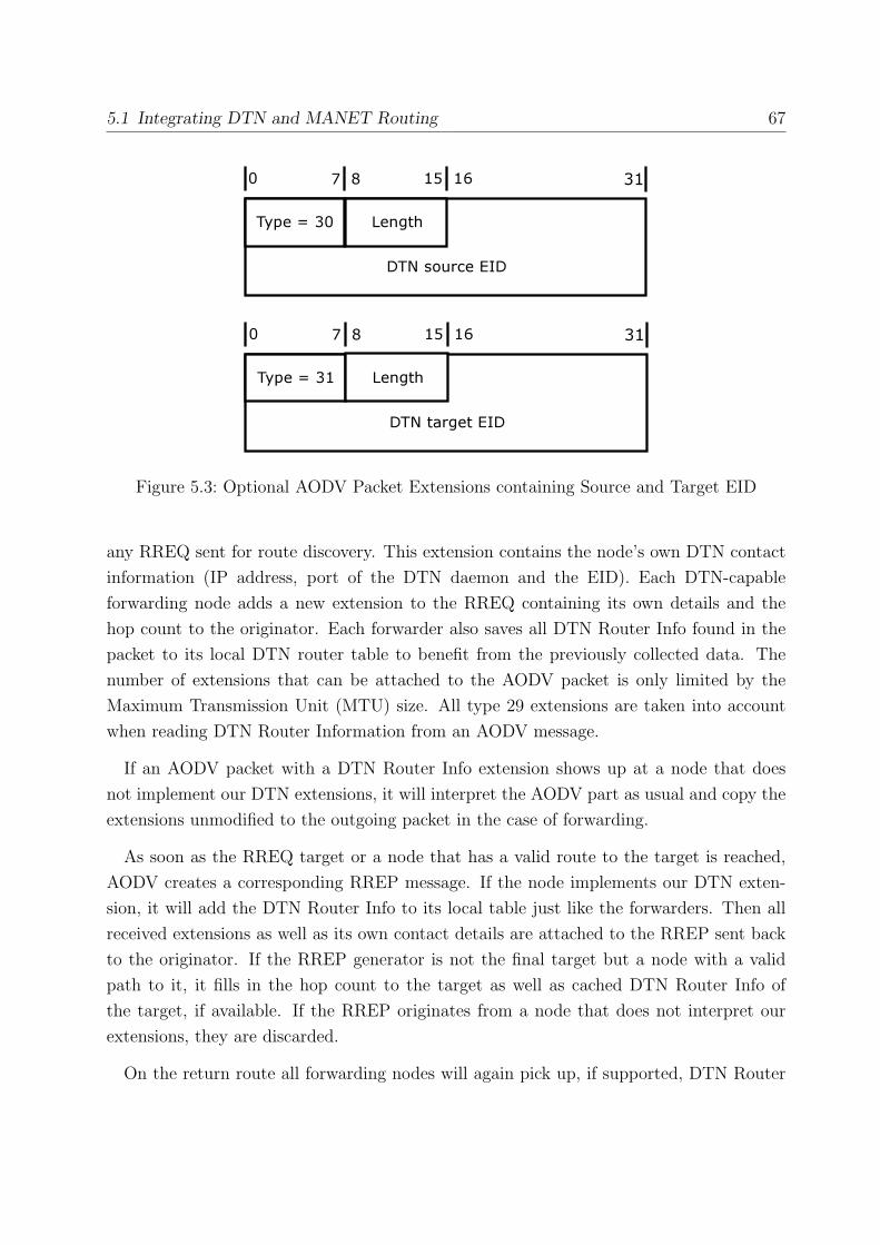
5.1 Integrating DTN and MANET Routing 67
Figure 5.3: Optional AODV Packet Extensions containing Source and Target EID
any RREQ sent for route discovery. This extension contains the node’s own DTN contact
information (IP address, port of the DTN daemon and the EID). Each DTN-capable
forwarding node adds a new extension to the RREQ containing its own details and the
hop count to the originator. Each forwarder also saves all DTN Router Info found in the
packet to its local DTN router table to benefit from the previously collected data. The
number of extensions that can be attached to the AODV packet is only limited by the
Maximum Transmission Unit (MTU) size. All type 29 extensions are taken into account
when reading DTN Router Information from an AODV message.
If an AODV packet with a DTN Router Info extension shows up at a node that does
not implement our DTN extensions, it will interpret the AODV part as usual and copy the
extensions unmodified to the outgoing packet in the case of forwarding.
As soon as the RREQ target or a node that has a valid route to the target is reached,
AODV creates a corresponding RREP message. If the node implements our DTN exten-
sion, it will add the DTN Router Info to its local table just like the forwarders. Then all
received extensions as well as its own contact details are attached to the RREP sent back
to the originator. If the RREP generator is not the final target but a node with a valid
path to it, it fills in the hop count to the target as well as cached DTN Router Info of
the target, if available. If the RREP originates from a node that does not interpret our
extensions, they are discarded.
On the return route all forwarding nodes will again pick up, if supported, DTN Router

68 Chapter 5: Application: Extending AODV with DTN
Information and update their local tables. If a node supporting DTN observes that DTN
extensions are missing in the RREP which did exist in the corresponding RREQ, it will
repair the RREP by adding the missing information. This is helpful in the case that the
RREP was generated by a non-DTN-enabled node. Such nodes will ignore our extensions
and send a plain RREP. Consequently, the originator would never get to know about
DTN routers on the path to the destination, which would be useful information for bundle
routing in case the end-to-end path breaks.
AODV silently drops RREQs and generates no RREPs if no route can be found. The
DTN Router Info collected during the expanding ring search is dropped with the RREQs.
DTN-enabled nodes can handle this problem because on each expanding ring search, one
DTN-capable node in the ring starts a timer when it receives the RREQ. A corresponding
RREP cancels the timer. If no route was found after a given timeout, the responsible
node generates a RREP itself containing the DTN Router Info collected so far. Telling the
originator by this RREP that an end-to-end path has been found while there is none would
confuse AODV. Therefore we are filling the AODV part of the RREP with meaningless
routing information, the routes listed in the RREP have zero lifetime. They are discarded
immediately at the originator and at any forwarder, and therefore are not disturbing the
proper AODV operation. The responsible router identifies itself by setting the T-bit. Only
the first node receiving the RREQ sets the T-bit in order to tell all subsequent nodes that a
responsible router has been determined. This avoids avalanches or RREPs being generated.
To reach out further than just one hop, each node stores whether it already had the role of a
responsible router. Each round of the expanding ring search will then bring up a different,
more distant responsible router, given the node pool is not exhausted yet. At n expanding
ring searches, this scheme limits the discovery process to the first n DTN-capable routers.
It also limits the amount of traffic generated by RREPs containing meaningless routes.
This should be considered more important as many paths followed during route search will
not lead to the destination and therefore should not produce unnecessary AODV messages.
AODV-DTN Interaction
The above scheme uses AODV as a vehicle to discover nearby DTN routers that can possibly
optimise transmission performance over unreliable paths or can be used as a fallback if no
end-to-end path can be found. The information about DTN routers collected in the AODV
messages needs to be made available to the local DTN router. Next to the AODV daemon
and the DTN router we need a third software tool: dtndctrl. This daemon is responsible

5.2 Testbed Setup 69
for feeding the details of nearby DTN routers, as observed by AODV in passing RREQs
and RREPs, into the local DTN router, as well as removing routers from it that weren’t
encountered within a certain timeout.
For DTN routing decisions, it’s assumed that a routing algorithm is in place determining
which bundles are sent to which DTN routers to maximise the success rate. For the
measurements, an epidemic routing protocol is desired, as it is simple and does not need any
extra information about the DTN routers (such as geographical location, past behaviour
or even distance as in hop count).
By combining AODV and DTN, we not only provide more options for packet transmission
to an application, increasing the message delivery rate in a MANET. We also provide each
node’s DTN router with information about surrounding DTN routers, giving DTN routing
protocols basic data for routing decisions and thus increasing the successful bundle delivery
rate for DTN itself.
5.2 Testbed Setup
For the implementation, testing and performance evaluation of our DTN Router Info exten-
sion to AODV and the dtndctrl daemon, we set up a testbed using the Kasuari framework.
The base filesystem image for all testbed nodes contains a 32-bit Debian GNU/Linux
unstable installation (installed and configured by us) that is equipped with the latest DTN
reference implementation (from the public DTNRG CVS repository6), the dtndctrl daemon
(developed by us) and AODV-UU version 0.8 (developed at Uppsala University). The
actual DTN router is a daemon called dtnd (part of the DTN reference implementation)
that is executed during the boot sequence. We did not configure any links or routes
in /etc/dtnd.conf and set the DTN routing type to flood to enable flooding (epidemic
routing). The AODV daemon aodvd is run during bootup as well, loading the necessary
AODV kernel module kaodv.ko automatically.
In the Kasuari framework kernel command line options (name=value assignments) are
used to pass parameters to guest nodes upon bootup. This allows us to have differently
configured machines running on the same base filesystem. For our AODV-DTN extension
testbed, our parameter set has to be extended to turn the DTN extensions and the DTN
6http://www.dtnrg.org/wiki/Code

70 Chapter 5: Application: Extending AODV with DTN
daemon on or off on certain nodes. The option dtn=enabled enables the AODV-DTN
extension in aodvd, and the option dtn density=10 sets the percentage of nodes that run
dtnd upon startup, in this case every tenth node. The startup scripts of aodvd and dtnd
had to be modified accordingly to enable them to read the new kernel command line
parameters from /proc/cmdline.
The kaodv.ko kernel module (from AODV-UU) was compiled against the Debian kernel
2.6.16 with Xen patch hg9697 from the Xen repository7. Two versions of this Linux kernel
were compiled, one for the host system (dom0) and one for the guests (domU), both placed
in the /boot directory on the host. The guest systems boot up and shut down controlled
by our kas-create and kas-destroy scripts. The decision was taken to run our tests with
ten nodes only for several reasons: scenarios don’t get overly complex, it takes less time to
start and shut down the nodes (which needs to be done a lot in the bug fixing phase) and
ten is a sufficient number to study AODV and DTN behaviour.
Figure 5.4: Chain Topology
To net the guests, we used two topologies: a simple node ”chain” to test for basic
functionality, and a more realistic random walk scenario, each of them with 10 nodes. The
”chain” topology is depicted in figure 5.4: each node is attached to a Linux bridge, whose
firewall rules suppress all layer-2 traffic between them except for the traffic between direct
neighbours in the chain. The firewall rules are Linux netfilter 8 settings that can be set
using the iptables user space tool with a bash script as in listing 5.1. A number of nodes
is passed to the script as an argument, and iptables is executed in a loop to allow traffic
flow between adjacent nodes. In order for this to work, all existing iptables rules need to
be flushed and a general DROP policy for the FORWARD chain is set, meaning that all
traffic forwarded by the bridge is dropped unless specific rules apply.
The second network topology that was put in place in a later stage of testing is using
the main network simulation approach of the Kasuari framework. A random walk mobility
file was generated for use with ns-2, where 10 nodes move into random directions in a field
7http://xenbits.xensource.com/xen-unstable.hg8http://www.netfilter.org/
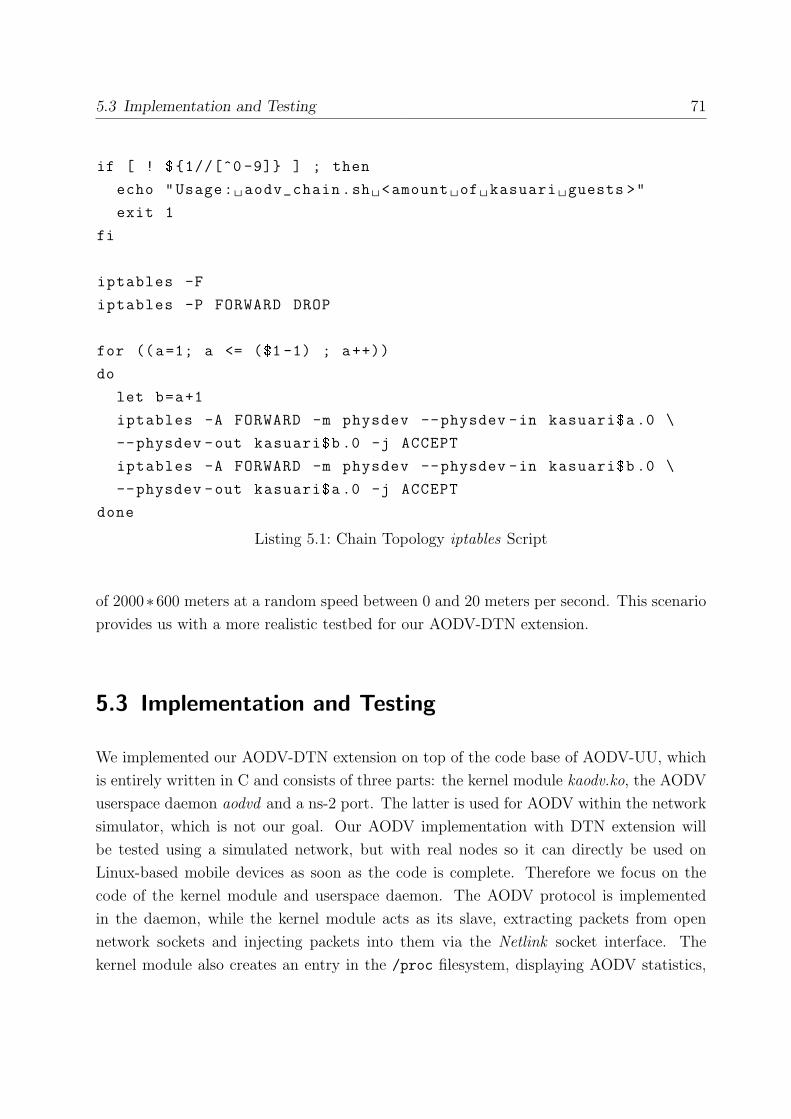
5.3 Implementation and Testing 71
if [ ! ${1//[^0 -9]} ] ; then
echo "Usage: aodv_chain.sh <amount of kasuari guests >"
exit 1
fi
iptables -F
iptables -P FORWARD DROP
for ((a=1; a <= ($1 -1) ; a++))
do
let b=a+1
iptables -A FORWARD -m physdev --physdev -in kasuari$a .0 \
--physdev -out kasuari$b .0 -j ACCEPT
iptables -A FORWARD -m physdev --physdev -in kasuari$b .0 \
--physdev -out kasuari$a .0 -j ACCEPT
done
Listing 5.1: Chain Topology iptables Script
of 2000∗600 meters at a random speed between 0 and 20 meters per second. This scenario
provides us with a more realistic testbed for our AODV-DTN extension.
5.3 Implementation and Testing
We implemented our AODV-DTN extension on top of the code base of AODV-UU, which
is entirely written in C and consists of three parts: the kernel module kaodv.ko, the AODV
userspace daemon aodvd and a ns-2 port. The latter is used for AODV within the network
simulator, which is not our goal. Our AODV implementation with DTN extension will
be tested using a simulated network, but with real nodes so it can directly be used on
Linux-based mobile devices as soon as the code is complete. Therefore we focus on the
code of the kernel module and userspace daemon. The AODV protocol is implemented
in the daemon, while the kernel module acts as its slave, extracting packets from open
network sockets and injecting packets into them via the Netlink socket interface. The
kernel module also creates an entry in the /proc filesystem, displaying AODV statistics,

72 Chapter 5: Application: Extending AODV with DTN
and reports unavailable routes to the daemon, initiating the AODV route search. As we are
extending the AODV protocol only, the kernel module code does not need to be touched.
The aodvd daemon creates entries in the kernel routing table using ioctls. This and the
packet extraction/injection via Netlink are the only kernel interactions. The whole AODV
packet generation and handling lies in the userspace daemon. The first step to add the
DTN Router Info extension was to create a new file for all DTN-related functions called
dtn.c and define a new type DTNRI according to the extension format in figure 5.2 (see
listing 5.2).
typedef struct {
u_int16_t dtn_port :16;
u_int32_t dtn_addr;
u_int8_t t:1;
u_int8_t hop_count :7;
u_int8_t option_eid :8;
u_int8_t eid_length :8;
char eid[MAX_EID_LENGTH ];
} DTNRI;
Listing 5.2: DTN Router Info Extension Type
The next step is to fill and attach this structure to any RREQ and RREP sent or for-
warded. This includes the optional HELLO messages: nodes may constantly send out
RREPs with TTL=1, announcing their presence to their direct neighbours. To fill the
fields, aodvd must know the local node’s DTN port number and EID. Therefore the fol-
lowing command line parameters are added:
-e, --use-dtn-eid EID Advertise local DTN EID.
-p, --use-dtn-port PORT Advertise local DTN port.
-t, --log-dtn-table N Log DTN node table to /var/log/aodvd.dtnlog
every N seconds.
Specifying the EID also generally enables the DTN extensions in AODV-UU, if it is not
given, AODV-UU behaves like plain AODV. If the port is not given, the default port of
dtnd (5000) is used. The last parameter allows the dumping of the collected DTN Router

5.3 Implementation and Testing 73
Info to a file in a given interval. This file is used by dtndctrl as described in the next
section.
To add an extension to a RREQ or RREP containing the local DTN Router Info, the
packet is passed to our function add local dtn routerinfo ext. This function creates a
new DTNRI structure in memory, fills in the local DTN contact details and increases the
hop count by one. This structure is padded to the 32-bit boundary and attached to the
AODV message before forwarding it.
In the handling routines for RREQs (in file aodv rreq.c) and RREPs (aodv rrep.c),
the message parser is extended to detect and interpret DTN Router Info extensions. To
identify our extension, a new extension type DTN ROUTER INFO EXT is defined and as-
sign the value 29 (taken from from the non-mandatory part of the available numbering
space[PBD03]) to it. A code snippet of the DTN extension handling is depicted in listing
5.3. The optional extensions of type 31 and 31 containing DTN source and destination
EID are treated in a similar manner.
As an extension of this type is encountered in an incoming packet, it is added to the
local list of DTN contacts using our function dtn table insert(). This function checks
the extension for bogus data, adds new entries to the list and updates existing ones. In
the RREQ parser routine, the extension is also added to another list named dtn rec: the
local cache of past RREQs. For each RREQ in this list a separate timer is started. This
timer is set to NetTraversalT ime − 2 ∗ HopCount ∗ NodeTraversalT ime. That value
ensures that the timer of the node which is the furthest away from the originator (identified
by the highest hop count) fires first, if it hasn’t been cancelled by a corresponding RREP
before. Even the timer of the node closest to the originator fires before the RREQ times out
(after NetTraversalT ime), ensuring that each RREQ will generate a RREP if DTN-aware
AODV daemons are around.
When a RREP is generated at the RREQ destination, our rreq copy extensions()
function copies all extensions from the RREQ to the RREP, and in the next step our
function add local dtn routerinfo ext() adds the destination’s DTN Router Info to it.
If the RREP is created at an intermediary node that knows a valid route to the destination,
our function add dest dtn routerinfo is called as well to add the contact details of the
destination DTN router to the RREP. The third case is a DTN-only RREP generated after
a RREQ timeout: an empty RREP structure is allocated, filled with an AODV route with
zero lifetime, and the cached extensions from the corresponding RREQ are appended to
the message as well as the local DTN contact details.

74 Chapter 5: Application: Extending AODV with DTN
case DTN_ROUTER_INFO_EXT:
if (dtn_enabled) {
// insert extension into (past) RREQ list
struct rreq_dtn_extensions_record *dtn_ext_rec;
if (( dtn_ext_rec =
(struct rreq_dtn_extensions_record *)
malloc(sizeof(struct rreq_dtn_extensions_record )))
== NULL) {
fprintf(stderr , "Malloc failed !!!\n");
exit (-1);
}
dtn_ext_rec ->ext=ext;
list_add (&dtn_rec ->rreq_dtn_extensions_records ,
&dtn_ext_rec ->l);
DTNRI *dtnri=(DTNRI*) AODV_EXT_DATA(ext);
// insert DTNRI extension into global DTN node table
dtn_table_insert(dtnri);
}
break;
Listing 5.3: DTN Router Info Extension Handler
If an intermediary node observes a passing AODV-only RREP generated by a non-DTN-
aware target node, and it has a corresponding RREQ with DTN Router Info extensions in
its cache, the RREP is ”repaired” by the intermediary by appending the saved extensions
from the cache to the RREP before forwarding it to the originator.
By default, the observed DTN Router Info is dumped to the file /var/log/aodvd.dtnlog
and is updated every second. Listing 5.4 shows the contents of this file on node 1 during
our test run using the chain topology (as in figure 5.4).
The actual code editing did not take place on the machine running the Kasuari framework
testbed. A set of scripts was used from time to time to copy the source code to the testbed
machine, compile it there and add the generated kernel module and aodvd executable to
the guest filesystem image. Existing guests were automatically shut down and a new set
of guests using the updated filesystem image were booted up. Kernel messages, aodvd
messages and logfile entries were obtained from the guests using the Xen console, which

5.3 Implementation and Testing 75
# Time: 13:30:00.527 , IP-addr: 10.0.0.1 , seqno: 19
# DTN EID IP Address Port Hop Count
dtn:// kasuari 10.dtn 10.0.0.10 5000 9
dtn:// kasuari 9.dtn 10.0.0.9 5000 8
dtn:// kasuari 8.dtn 10.0.0.8 5000 7
dtn:// kasuari 7.dtn 10.0.0.7 5000 6
dtn:// kasuari 6.dtn 10.0.0.6 5000 5
dtn:// kasuari 5.dtn 10.0.0.5 5000 3
dtn:// kasuari 4.dtn 10.0.0.4 5000 3
dtn:// kasuari 3.dtn 10.0.0.3 5000 1
dtn:// kasuari 2.dtn 10.0.0.2 5000 1
Listing 5.4: Sample Contents of /var/log/aodvd.dtnlog
can connect to the primary console of each node. Debugging also took place over the guest
console, as the gdb (the GNU project debugger)9 is contained in the filesystem image.
Whenever testing of the code was necessary it could be done in the live testbed right
after starting the testbed nodes, as the filesystem image is constantly updated with the
latest application binaries by scripts. In the early development stages, the chain network
configuration (as in figure 5.4) was mostly used for debugging, as the node locations are
static and the topology is as simple as possible. When the AODV-DTN code matured, we
switched to the random walk scenario to challenge our implementation with a more realistic
setting. Using Wireshark and nam, following the events in the network in real-time was
possible. Recording all network traffic to trace files allowed us to compare our observations
later. Bugs in the implementation were reproduced, isolated, analysed and fixed quickly.
Also, testing was done without modifying the local network configuration and without
risking a kernel crash on the development machine, as the AODV kernel module ran in
Xen virtual machines completely isolated from the host platform.
Dtndctrl
In order to pass DTN Router Information collected by AODV to the dtnd, dtndctrl was
developed. It is a Perl script and runs as a background daemon on each testbed node.
The script constantly reads the contents of /var/log/aodvd.dtnlog to obtain the latest
9http://www.gnu.org/software/gdb/

76 Chapter 5: Application: Extending AODV with DTN
DTN Router Info and keeps it in an internal list. As new routers show up in the file, they
are added to that list, as they disappear, they are removed after a timeout. Whenever the
list contents changes, dtndctrl creates a set of commands that is fed to the dtnd via its
socket-based control interface, accessible via the local port 5050. The commands create
a link and a route to the DTN router found by our extended AODV. For instance, the
commands sent to dtnd to introduce a new DTN router with EID dtn://kasuari10.dtn
and IP address 10.0.0.10 are depicted in listing 5.5.
link add 10_0_0_10 10.0.0.10:5000 ONDEMAND tcp
route add dtn:// kasuari 10.dtn/* 10_0_0_10
Listing 5.5: Sample Commands sent to dtnd
The link name (10 0 0 10) is derived from the IP address, ensuring it’s unique as long
as IP addresses are. A route is added that uses the new link to route traffic to the node
with the corresponding EID.
During the debugging and testing phase of the AODV-DTN extension and dtndctrl, we
encountered some trouble with the DTN reference implementation (dtnd). As soon as
the routing type was set to ”flood” in /etc/dtnd.conf, we registered frequent crashes of
dtnd, sometimes caused by vast memory usage of the process. The overall bundle handling
slowed down significantly after a few minutes of testbed operation. Bundles sometimes
oscillated between two DTN routers and not all existing links were incorporated in the
flooding.
Due to this severe bug in the flooding code we implemented a simplistic, but surprisingly
useable bundle routing scheme ourselves. Instead of flooding the bundles to all DTN
routers in range, we modified dtndctrl to only add links and routes to nodes with a higher
host number than the current one. This simple approach ensures that bundles can pass
each DTN router only once, avoiding loops. Our routing algorithm is useable for basic
measurements, until the flooding code is fixed in the DTN reference implementation. It
has two major drawbacks, though: the target node is fixed and cannot change during the
testbed run, and the routing by host numbers does not bear any logic, as the numbers say
nothing about whether a bundle router is close to the destination or not. It has been put
in place to avoid flooding loops in our measurements and is by no means a replacement for
a real DTN routing algorithm, which is out of the scope of this thesis.
The host number is derived from the node’s hostname, which follows the scheme kasuariX

5.4 Measurements and Observations 77
in our testbed, where X is the node number. Each route we add during the testbed run
points to a fixed destination EID, given to dtndctrl as a startup parameter. This way,
we can disable flooding on the nodes and pretend that each DTN router discovered is the
beginning of a possible path to the destination. If multiple routes point to the same target,
dtnd copies the bundle to all of them.
5.4 Measurements and Observations
After setting up a testbed and completing the development and testing phase of aodvd with
DTN Router Info extension and dtndctrl, measurements were conducted in random-walk
wireless networking scenarios similar to the one described in section 5.2, but with many
different parameter sets. Finding out about two different things was of particular interest:
how much overhead the extension produces compared to unmodified AODV and if our
goal to increase the packet delivery rate in a challenged network by combining AODV with
DTN is achieved.
5.4.1 DTN Router Info Extension Overhead
The AODV routing protocol is reactive, meaning that AODV messages are only generated
when there is demand to determine a new route. Therefore AODV causes the minimum
possible traffic impact on the network. Our approach increases the size of an AODV
message on every DTN enabled node it passes by adding an extension. We are also altering
the AODV paradigm by generating RREPs after failed route searches. Although their
number is limited, they lead to increased packet and data load in the network. The
following measurements visualise the impact of our DTN Router Info extension and tell
whether the extra traffic is comparative.
The setup used for the measurements is similar to the setup used in the development
process described in 5.2. In addition to the 10 node random walk, scenarios with 20, 40
and 80 nodes were run. The field size was always 1000 ∗ 1000 meters and nodes move at
speeds between 0 and 5 meters per second into a random direction. To trigger the AODV
route search, a ping is sent every second from the node with the highest number to node
number one. AODV is enabled on all nodes in all tests, but only a varying percentage
(0%, 5%, 10%, 20%, 50% and 100%; called ”AODV-DTN density” in the tables) of nodes
support our DTN Router Info extension. Each measurement is repeated twice, leading to

78 Chapter 5: Application: Extending AODV with DTN
a total number of 3 ∗ 4 ∗ 6 = 72 runs. In the tables and graphs the average values (AODV
message count and size of all AODV messages transferred) of the three runs are shown, as
they produced very similar results.
During each measurement run, a ping (ICMP echo request) is sent every second from
the node with the highest number (originator) to the node with the lowest number (tar-
get), triggering AODV RREQs. Compared to the scenario in section 5.2, the traffic flow
direction has been reversed for a simple reason: the target node number has to be con-
figured in the ping script. If the node with the highest number would be the ping target,
the measurement script would need to be modified whenever the total node count in the
scenario changes. Using node number one as the fixed target node in all scenarios doesn’t
require a modification of the script and therefore simplifies the measurement process.
In all AODV-DTN densities except 0% the originator and target use the DTN Router Info
extension, overriding the desired percentage. The network simulation runs for 10 minutes
while all traffic sent on all nodes is captured using tcpdump. After each measurement, all
virtual nodes are shut down and restarted, the packet traces are concatenated into a single
file and everything that is not an AODV message is filtered out using tshark. Using scripts
that involve tshark and awk, the total average AODV message count and data volume is
extracted from each measurement dump file and printed out in tables 5.1 and 5.2. The
measurement values are also displayed in figures 5.5 and 5.6.
Looking at the measurement results in figures 5.5 and 5.6 reveals that there is no obvious
correlation between the amount and size of AODV messages and the amount of nodes in the
network simulation. A high node density of 80 nodes on 1000 ∗ 1000 meters means a high
probability for the existence of an end-to-end path, therefore less RREQs need to be sent
in that scenario until a route is found. Generally, as the four scenarios with different node
counts are randomly generated, it depends on the originator’s location within the field if
many AODV messages are triggered or not. If the originator is in an isolated position with
only a few contacts in its communication range (250m, the default transmission radius
of ns-2’s 802.11 simulation) during the simulation, only very few AODV messages are
forwarded and few routes are found. If it has many contacts that have many contacts
themselves, more RREQs are forwarded and more RREPs are generated.
More important than the relationship between node count and AODV messages is the
message volume on different AODV-DTN densities. The more nodes supporting DTN
Router Info extension, the more AODV packets are generated (RREPs for failed AODV
route searches) and the higher is the total AODV traffic volume (due to extension-enlarged

5.4 Measurements and Observations 79
Figure 5.5: Number of AODV Messages sent in different Testbed Configurations
AODV-DTN density: 0% 5% 10% 20% 50% 100%
10 nodes 707 1451 1440 1448 1580 1661
20 nodes 520 515 526 709 944 1314
40 nodes 1841 2895 3302 4495 4888 5379
80 nodes 463 564 467 631 589 719
Table 5.1: Number of AODV Messages sent in different Testbed Configurations

80 Chapter 5: Application: Extending AODV with DTN
Figure 5.6: Total AODV Message Volume sent in different Testbed Configurations
AODV-DTN density: 0% 5% 10% 20% 50% 100%
10 nodes 45 111 164 165 198 215
20 nodes 33 52 53 76 105 167
40 nodes 118 313 377 573 780 1085
80 nodes 29 61 49 74 80 141
Table 5.2: Total AODV Message Volume sent in different Testbed Configurations

5.4 Measurements and Observations 81
AODV messages and additional RREPs). Looking at the ten node configuration in figure
5.5 it’s easy to grasp that by just enabling DTN Router Info extension support on five
percent of the nodes (in this case just on the target and originator) more than doubles the
amount of AODV messages sent (1451) compared to the setup when none of them uses the
extension (707). This is due to the extra RREPs that are generated on failed AODV route
searches. The amount of data transferred in AODV messages also more than doubles in the
ten node scenario from 45 kBytes at 0% AODV-DTN density to 111 kBytes at 5%. In the
80 node measurement, the jump from zero to five percent AODV-DTN density only leads
to 564 instead of 463 AODV messages being sent. This is a minor increase as AODV route
discovery is already quite successful due to the high node density. Not many extra RREPs
for failed route searches appear. The jump in message size is much bigger, more than twice
as many kilobytes (61 instead of 29) are transferred in the form of AODV messages as
DTN Router Info extensions are added by originator, target and forwarders.
The mobility patterns used in our measurements were random-generated. During some
of the testbed runs, situations emerged where lots of traffic flowed in the network, but
actual end-to-end AODV paths between originator and target were rarely ever found. In
certain node constellations, the originator is trying to establish an AODV route following
paths into many different directions, but unfortunately no path to the destination can be
found, either because of unfavourable network partitioning or because of paths that are
just too long. Thus, many additional RREPs containing DTN Router Info are generated.
We believe that such a condition emerged in the 40 node scenario, as much higher total
message counts and bytes than in all other scenarios were recorded (tables 5.1 and 5.2).
This is pure coincidence and not a problem, as we are more interested in the relative gains
in message count and size when enabling AODV-DTN than in their absolute values.
Generally, enabling the DTN Router Info extension on all nodes opposed to zero nodes
more than doubles the AODV message count in most cases. The amount of AODV traffic,
which is important for battery-driven nodes and in clogged wireless networks, usually
becomes about five times as much. Nevertheless, the actual numbers are quite low: in
the worst case (40 nodes), 5379 instead of 1841 AODV messages were sent, increasing the
overall AODV traffic volume from 118 kilobytes to a megabyte, which is not too much for
a network of 40 nodes running for ten minutes. In the other measurements, the numbers
were much lower than this. However, the benefit of having an alternative, asynchronous
communication option (DTN) should certainly outweigh the impact of our modifications.

82 Chapter 5: Application: Extending AODV with DTN
5.4.2 Message Delivery Rate
To find out whether and how the addition of a second communication option could increase
the message delivery rate in a sparse wireless networking scenario with unreliable paths,
the same testbed setup as in the previous section was used in a set of measurements. We
picked the interesting random-walk scenario with 20 nodes, as it starts with a period where
no end-to-end AODV path from the originator to the target is available. After about 90
seconds simulation time, a (rather unstable) end-to-end path becomes available.
Figure 5.7: Tool Setup for AODV-DTN Measurements
We set up our set of tools as shown in figure 5.7 to allow for both end-to-end and DTN
bundle communication. The originator and target (orange boxes) run several applications
and communicate over a testbed network in which the nodes are AODV- and/or DTN-

5.4 Measurements and Observations 83
capable. On both endpoints, dtndctrl is used to feed DTN Router Info obtained by our
AODV implementation (aodvd) to the DTN router (dtnd). To generate the packets to be
sent from the originator to the target in our measurements, the TCP exchange generator
(tcpx ) is employed. It can produce various TCP traffic patterns on the originator and
receive and analyse those packets on the target. The generated traffic is not directly sent
to the target, but to a local instance of dtntcp, a transport layer proxy for TCP over
DTN[OK05-TR]. Upon an incoming local connection, dtntcp first tries to connect to the
target machine directly, using AODV to find an end-to-end path. If no such path is found
and the connection attempt fails, dtntcp reverts to DTN and forwards the data as bundles.
This decision making process is repeated every time data is received from tcpx in order to
quickly react to topology changes, maximising the delivery rate. On the target, the data
is received by tcpx either directly from the remote dtntcp over an AODV path or from the
local dtntcp that picked up the incoming bundles from the dtnd [OKD06].
The tcpx tool was set up to send a 1 kByte TCP packet to the local dtntcp every 15
seconds in a total measurement time of 600 seconds (10 minutes), leading to a total 40
packets sent per measurement run. The maximum bundle size was configured to 1 kByte
in dtntcp. Therefore, a bundle is generated for every packet received when there is no
end-to-end path available. A bundle expires after a 300 second lifetime if it hasn’t been
delivered to the target in that time frame.
The measurement procedure is described in the following. After creating the 20 testbed
nodes using the Kasuari framework, the network simulation in ns-2 is started. Instances
of tcpx and dtntcp are launched on node one (the originator). Two instances of tcpx in
server mode (to receive bundles from the local dtntcp and end-to-end transmissions) as
well as one dtntcp are executed on node twenty (the target) as in figure 5.7. All nodes in
the measurement scenario run our AODV-DTN implementation, and a varying percentage
of them additionally runs the DTN daemon as well as dtndctrl.
The dtntcp on the originator receives packets from the local tcpx client on port 8000
and attempts for each of them to forward it directly to the target tcpx listening on port
8888. If the connect call fails and no end-to-end path is found, the packet is then formed
into a bundle and transferred to the originator’s local dtnd listening on port 5000. The
dtnd then follows the bundle routing instructions received by dtndctrl, as long as some
DTN Router Information has arrived in AODV messages from neighbour nodes. The
bundle is forwarded to all reachable DTN routers with a higher node number than the
originators number, which is always one. As the topology changes in the course of the

84 Chapter 5: Application: Extending AODV with DTN
network simulation, bundles are forwarded further and eventually reach their destination
or they time out and are discarded by an intermediary node. Is the bundle received by the
dtntcp on the target node, it is transformed back into its original TCP packet form and
forwarded to the second local tcpx listening on port 9000 on the target, as shown in figure
5.7.
Table 5.3 contains the data from the tcpx and dtntcp log files generated on the originator
and target during the measurement runs with 0%, 10%, 20%, 50% and 100% of the nodes
running dtnd and dtndctrl. As the same mobility file was used in every measurement, it is
not surprising that in each run 31 packets were sent and received over and end-to-end (e2e)
path. The 9 remaining packets are generated at times where no end-to-end path from the
originator to the target is available. Therefore, these packets are simply dropped at 0%
DTN density, as there is no bundle router to store and forward them. This AODV-only
scenario leads to a message delivery rate of 77.5%, as only 31 out of 40 packets reach their
destination.
DTN Packets Bundles Packets Bundles Delivery
density sent (e2e) sent received (e2e) received rate
0% 31 - 31 - 77.5%
10% 31 9 31 6 92.5%
20% 31 9 31 7 95.0%
50% 31 9 31 9 100.0%
100% 31 9 31 9 100.0%
Table 5.3: Message Delivery Rate at different DTN Densities
As soon as DTN is enabled on 10% of the nodes, bundles can be stored in the local
bundle router and eventually forwarded to nearby routers. Some of those adjacent DTN
nodes may be dead ends, as they may never encounter other routers that could help in
delivering the bundles to their final destination during the whole simulation. As the DTN
density increases, chances become higher that the bundle can be delivered before timing
out, as more nodes are able to store and forward them. When 50% or 100% of the nodes
employ DTN in our 20 node scenario, all messages are delivered within the measurement
time frame.
In a sparsely populated random walk MANET scenario using AODV, enabling our
AODV-DTN implementation on just a small percentage of nodes dramatically increases
the rate of successful message delivery compared to an AODV-only setup. Using a sophisti-

5.5 Conclusion 85
cated DTN routing protocol might even top the rates observed with our simplistic routing
approach. Messages delivered via DTN may arrive at the destination with a delay, thus
DTN is not suitable for applications with real-time requirements such as Voice-over-IP.
Asynchronous communication as described in the Drive-Thru Internet use case (section
2.1.2) is feasible, though.
5.5 Conclusion
In this chapter the idea of enhancing MANETs in order to let applications choose their
preferred way of communication (end-to-end or store-and-forward) with their peers was
explored. After introducing AODV and DTN as the two communication options, we pre-
sented an extension to AODV to discover nearby DTN routers during route search. This
data is then used by our tool dtndctrl to enhance the view of DTN routers. Combined
with path characteristics and peer reachability information from AODV, applications are
able to make sensible choices on which communication mechanism to use.
We explained how to set up a testbed using our Kasuari framework for development and
testing of our extension and described the implementation process. Finally, we conducted
measurements to confirm the benefits of our extension in an emulated, but realistic wireless
MANET networking environment. In the implementation and measurement phases, the
Kasuari framework proved to be extremely helpful. In fact, without a way to develop and
test on regular Linux machines and simulate a wireless network, this process would have
taken significantly more time and resources. Directly after completing the development,
our software can be used on any Linux host with no need for porting code written for
a simulator to a real network node, thus eliminating a big part of the release process.
Especially by automating tedious processes such as compiling, inserting the binaries into
the guest image and powering the testbed nodes up and down enabled us to concentrate
on the protocol extension development and allowed us not to be concerned about our
platform. The coding took place on a different machine (a laptop) using SSH connections,
which allowed us to test changes made to our implementation within very little time and
use the testbed from any place with a network connection. Replacing our simple ”chain”
topology with a sophisticated, simulated wireless network with random node motion took
only minutes. With real hardware nodes this would have been much more elaborate.
For protocol debugging, we captured all network traffic with tcpdump to analyse it in
Wireshark later, which is a comfortable and advanced way to examine the packet flow and

86 Chapter 5: Application: Extending AODV with DTN
find implementation errors. All traffic from all virtual network interfaces was captured
at one single point - the Kasuari framework host machine. Collecting log files from the
copy-on-write images was just as easy, so there was no need at all to collect logs from
different live machines spread in the testbed.
Our AODV-DTN overhead measurements ran fully automated, taking roughly six hours
to complete with all different scenario sizes and DTN densities. Any manual interaction
was phased out with the help of the Kasuari framework. The delivery rate measurements
show that combining end-to-end TCP with DTN-based store-and-forward communication
improves throughput in a sparse MANET compared to only using end-to-end TCP as
provided by AODV. The increased AODV message size and additional RREPs do increase
the overall amount of data transferred in the network, but the benefits of the increased
rate of successful message deliveries far outweigh this downside.
All in all, the AODV-DTN extension was an ideal scenario to test the capabilities of the
Kasuari framework and to prove that our idea works out the way we anticipated it to be.
Open issues
There are a few open issues concerning the implementation and measurements of our DTN
Router Info extension to AODV and the dtndctrl tool. Our initial implementation of the
AODV extension served us for the measurements purposes within this thesis, but does not
include all features proposed in [OKD06]. The optional DTN Routing Metric fields of the
DTN EID extension may be used to transmit additional routing metrics for different DTN
routing protocols such as PRoPHET[LD06]. For our tests with epidemic routing this was
not necessary. Also, the T-bit field is set in the AODV extension, but is not interpreted as
of now, as the concept of defining ”responsible routers” as mentioned in [OKD06] was not
necessary for RREP timer activation and deactivation in our measurements. If the target
cannot be reached via AODV, the node furthest away from the originator would always
send the first ”custody” RREP as its timer runs out first, cancelling the timers on all other
nodes on the path. These minor features are missing in our implementation and can easily
be added to our code in the future, should they ever become necessary.
The implementation of AODV-DTN differs from the workshop paper in another minor
detail. If an intermediary node on a AODV route search knows the DTN contact informa-
tion of the target, it is supposed to either forward the RREQ if the target is more than
a few hops away or immediately reply with a RREP if the target is close. In our imple-
mentation, such a custody RREP is only generated if the intermediary node has an active

5.5 Conclusion 87
AODV route to the target, as all locally cached DTN contact details are appended to the
RREQ or RREP anyway. This ensures that the maximum amount of valid DTN Router
Information is collected in the route search and returned to the sender.
The set of measurements ran only supports that our basic idea works and nodes do benefit
from combining AODV and DTN. However, to study the impact of mobility and different
mobility models on the delivery rate and additional data traffic, more measurements are
necessary. Generating ns-2 scenarios for the Kasuari framework using different mobility
generators for different movement models such as the Freeway Model (nodes moving like
cars along a busy street) or the Manhattan Model (nodes move like cars in a chessboard-like
street layout) could provide interesting results[BSA03].
Running another daemon (dtndctrl) to communicate DTN Router Info obtained via
AODV to the dtnd is certainly not the best solution. Therefore it may be worthwhile to
look into improving the API between the routing protocol and dtnd, possibly extending
dtnd in the process and supersede dtndctrl.

88 Chapter 5: Application: Extending AODV with DTN

Chapter 6
Prospects and Conclusion
The final chapter reveals some ideas and developments that did not make it into the first
version of the Kasuari framework, but may be worthwhile researching and implementing
in the future. It concludes with a summary of the achievements in this diploma thesis.
6.1 Future Work
Some components and initial ideas were not incorporated into the Kasuari framework.
Future work may include their addition to the framework after solving licensing issues and
creating appropriate interfaces. This section lists a few candidates that would be pleasing
to see in our framework in the future, but are out of scope in the time frame of this thesis
development.
6.1.1 Advanced Simulation
Ns-2 is our network simulator of choice, as it is Free Software, is widely used and accepted
in the research community and features an emulation mode that allows the attachment
of real nodes. The latter is critical for the Kasuari framework, but rare among network
simulators. The ns-2 development has slowed down significantly in the recent years, and
numerous existing add-ons are not fully integrated into the main source tree, but are only
available as patches for certain ns-2 versions. Thus, ns-2 does not contain simulation
support for many recent, emerging technologies. Currently we are limited to ns-2, but in
89

90 Chapter 6: Prospects and Conclusion
the future we may be able to replace it with a different simulator, such as OMNeT++1 or
MIRAI-SF 2, by enhancing their code with an emulation feature. As of writing this thesis,
these two network simulators offer no emulation mode and were therefore not mentioned
as possible testbed components in chapter 3.
OMNeT++ is a modular simulation environment, comprised of various components to
simulate different network types, protocols and applications. Its strong GUI support simpli-
fies the simulation setup and control, and it also contains an integrated result visualisation
tool. IPv4 and IPv6 are supported, as well as different mobility simulations with ad-hoc
routing protocols. OMNeT++ development is very active whilst also being community-
driven, and the software is freely available for academic and non-profit use. To use it
in the Kasuari framework, two major challenges arise: modifying the code for real-time
simulation and interfacing to a virtual network device.
The same challenges apply when preparing MIRAI-SF for integration in the Kasuari
framework. MIRAI-SF is a large-scale network simulator for wired and wireless net-
works developed at the National Institute of Information and Communications Technology
(NICT) in Japan. Each simulator component is built as a plug-in agent, which allows
for maximum flexibility and custom-built agents when creating simulation scenarios. The
Java platform provides strong GUI support and cross-platform availability. The software
consists of three blocks: simcore (the simulator itself), animator (to visualise simulation
runs) and the network model builder (to create the simulation scenario, see figure 6.1).
Large simulations with up to 30.000 nodes can be created in the network model builder,
which also supports different mobility models.
The actual MIRAI-SF simulation is then performed by the command-line based simcore,
producing a large result file. This can be converted into another file which can be loaded
in the animator. The animator provides playback controls and zooming to accurately
visualise the simulation run. Like OMNeT++, MIRAI-SF does not yet support real-
time simulation and interfacing to virtual network devices. As parts of MIRAI-SF are
available to the public only in binary form, we signed an agreement with NICT to provide
us with the source code. Currently under investigation is its potential to replace ns-2 in
the Kasuari framework, as its network modeller is a powerful feature we would like to see
in our framework.
1http://www.omnetpp.org/2http://www2.nict.go.jp/w/w121/mirai-sf/overview e.html

6.1 Future Work 91
Figure 6.1: MIRAI-SF Screenshot
6.1.2 Advanced Visualisation
Visualisation using nam (network animator, part of ns-2) is very limited. Nam has origi-
nally been designed to monitor traffic flow in a wired network simulation, the support for
wireless networks was added later and remained rather incomplete. Data transmission be-
tween nodes is displayed as expanding circles. These circles are only visible for milliseconds
in slow motion nam playback and do not depict the maximum transmission range, the traf-
fic flow, its destination or type. By looking at a nam visualisation it is nearly impossible to
tell who is communicating with whom. Scrolling and zooming in nam is inconvenient, and
the performance of the graphics display is poor as well as CPU-intensive even on powerful
hardware. In addition, misplaced node descriptions make it hard to distinguish nodes from
each other.
The iNSpect visualisation tool improves on some of nam’s flaws. Its main advantage
is the use of OpenGL for drawing, allowing for hardware accelerated graphics display
that significantly reduces CPU load. Node numbers are readable and nodes are colour

92 Chapter 6: Prospects and Conclusion
coded according to their role (sender, receiver, forwarder) and indicate successful or failed
transmissions. Lines are drawn between nodes to indicate active routes. iNSpect provides
more sophisticated playback controls than nam, allowing for jumps and different playback
speeds in either direction.
Figure 6.2: iNSpect Screenshot
Screen shots and even movies can be created by a mouse click in the GUI. It supports
geometric overlay objects (such as circles and rectangles) as well as background images
to further enhance the visualisation. Additionally, it supports direct visualisation of ns-
2 mobility files obtained from a mobility generator, without the need for a ns-2 run to
generate trace files[KCC04]. Although iNSpect is far superior to nam, we do not include it
in the Kasuari framework for two reasons: it’s not publicly available under a free software
licence, and it does not support real-time visualisation. To obtain the software the author

6.1 Future Work 93
must be contacted via e-mail3 and he will reply with a source code tarball. The author will
accept bug reports, without explicitly encouraging the community to continue developing
iNSpect. The lack of a free software licence makes iNSpect incompatible with the Kasuari
framework. Real-time visualisation is the other aspect that we require for our framework.
Nam accepts a UNIX pipe as input ”file”, allowing it to visualise ns-2 trace data while
the simulation runs. iNSpect does not support this feature. A live network view may be
required by researchers to manually trigger certain events on the simulation nodes or to
monitor node properties such as the current routing table as soon as two nodes get close
or move away from each other.
Neither iNSpect nor nam are currently ideal for visualisation in the Kasuari framework,
thus future work may include the development of a new visualisation tool. It should be
C/C++/OpenGL based for performance reasons and platform independence, able to read
live trace files and possible packet traces in the pcap[Bul01] format, as produced by tcpdump
and Wireshark. By reading live packet traces, additional data is obtained which can also
be visualised by colour coding nodes, links, routes and packets according to their type. The
command line tool tshark is able to identify a wide range of network protocols. It could be
used to identify AODV RREQs and RREPs in the packet trace and colour the nodes and
links respectively, delivering more insight on certain protocol behaviour. Such a feature
would consume lots of resources, therefore performance optimisation should be a main goal
during development. Furthermore, the visualisation window should allow for continuous
zooming, panning and rotating the scene using a viewport camera and three-dimensional
node positioning. This should be possible by supplying the node coordinates with an extra
value (z).
6.1.3 Live CD
Installing the Kasuari framework has been made as simple as possible because of the Debian
packages we provide. Nevertheless, the installation needs some time, requires basic Linux
skills and demands a free partition on the computer’s hard drive. This may be a hurdle for
inexperienced users and may prevent some people from trying it, as it requires elaborate
and potentially harmful disk partitioning operation. A solution that is very common in
the Linux world is to create a live CD. Such a disc contains a fully configured GNU/Linux
system that is bootable directly from the CD. The computer’s hardware is auto-configured
3mailto:[email protected]

94 Chapter 6: Prospects and Conclusion
on system boot, usually requiring no user interaction or knowledge of that process. A
temporary RAM-disk is created to provide for write operations, so that write access to any
other system drive is not necessary. It leaves the computer’s hard drives and operating
systems untouched.
A live CD with the Kasuari framework would boot the pre-configured Xen kernel and
Debian GNU/Linux. It should be based on an existing live CD project, such as KNOPPIX4
to make use of their hardware auto configuration tools. Researchers could download the
CD image, record it to a disc and explore the Kasuari framework on any off-the shelf PC
hardware. If they like it, they can choose to perform a full hard drive installation in order
to be able to modify configuration files and disk images. If not, they can remove the CD
from the computer with no harm done.
6.2 Conclusion
In this diploma thesis we introduced the Kasuari framework, a wireless network testbed
platform, and described an extensive application scenario for this technology. The first
chapters concentrate on the requirements (2), related projects (3) and the design and
implementation (4) of the testbed software, while the second part of this thesis (chapter
5) mainly deals with the integration of the AODV routing protocol with DTN as a sample
application scenario. The measurement results obtained in this use case were published
as part of a scientific publication[OKD06] and the experience gained during the protocol
development was directly used as input to further improve the framework.
As the Kasuari framework provides a generic base for testing networked applications
of all kind, there is a wealth of possible appliances. The Drive-Thru-Internet project
will probably adopt it to emulate highway data transmission scenarios and test protocol
implementations in the testbed as well as on the autobahn. The developer of the FLUTE
implementation Papageno[Loo05] is exploring the possibility of performance testing in the
Kasuari framework. Real Voice-over-IP phones may be connected to the simulated network,
while PBX applications like Asterisk5 may run on the guest nodes, connecting the calls.
Such a setup allows to evaluate the impact of network conditions like delay and packet
loss on phone calls and to generally test a VoIP network setup before it is deployed. The
Linux operating system on the guests and host sets virtually no limits to the types of
4http://www.knoppix.org/5http://www.asterisk.org/

6.2 Conclusion 95
applications, services and network configurations employed as well as to hardware devices
connected.
This thesis is not only meant to describe the idea and the development of the Kasuari
framework, but also to give practical usage instructions in a detailed application scenario.
It also contains details on how to obtain, install and operate the framework in appendix
A. Open issues in the design and implementation are enumerated and discussed in section
4.5, and ideas for further development that were out of the scope of this thesis and thus
not included were detailed in section 6.1.
Generally, the demand for network emulation environments is growing and new solutions
keep appearing on the market. Recent advancements in virtualisation technology lower the
hardware requirements and allow for much larger emulation scenarios. The next generation
of network testbeds based on this technology is set to replace the existing solutions. The
Kasuari framework is one of them.
All in all, the Kasuari framework is a blend of established (such as ns-2) and emerging
(such as Xen) software components, easy-to-use scripts, convenient packaging and self-
explanatory sample testbed scenario files. Although it was mainly intended for network
protocol development and testing, which it proved to be capable of during the development
of the AODV-DTN extension (see chapter 5), it can be applied in many different fields of
computer network research due to its flexibility. Especially for protocol development and
testing, the Kasuari framework has the potential to become an indispensable tool.

96 Chapter 6: Prospects and Conclusion

Appendix A
Installation Instructions
These installation instructions are a snapshot of the Kasuari framework wiki page1, which
is constantly updated and always holds the latest revision of this document.
Installation Options
The Kasuari framework is available as source code from our Subversion repository and as
pre-compiled Debian packages for different x86 architectures. The installation using the
Debian packages is highly recommended as it is quicker, easier and more reliable than
building it from source.
Installation on Debian GNU/Linux sid (unstable)
1. Become root
2. Add the following line to your /etc/apt/sources.list
deb ftp://ftp.tzi.de/tzi/dmn/kasuari/debian sid main
deb-src ftp://ftp.tzi.de/tzi/dmn/kasuari/debian sid main
3. Run apt-get update
4. On a 32bit system run: apt-get install xen-hypervisor-3.0-i386 xen-utils-3.0
bridge-utils iproute libc6-xen ethtool initrd-tools kasuari
1https://prj.tzi.org/cgi-bin/trac.cgi/wiki/Kasuari
97

98 Appendix A: Installation Instructions
5. On a 64bit system run: apt-get install xen-hypervisor-3.0-amd64 xen-utils-
3.0 bridge-utils iproute ethtool initrd-tools kasuari
6. PLEASE NOTE: Some Xen packages have recently been updated and renamed
in Debian. Please download and install the xen-hypervisor-3.0 and xen-utils-3.0
packages manually from our cache (ftp://ftp.tzi.de/tzi/dmn/kasuari/debian-2.
6.16/) until the next version of the Kasuari framework is released.
7. Install the kernel images by running apt-get install linux-xen0-2.6.16-kasuari-
dom0-2-xen-686 linux-xenu-2.6.16-kasuari-domu-2-xen-686 cowloop-modules-
2.6.16-kasuari-dom0-2-xen-686 cowloop-utils (replace “686” with “k7”, “amd64-
k8” or “emt64-p4” depending on your machine type)
8. If you get a hotplug warning from the udev package, purge it with dpkg -P hotplug
9. Create a dom0 initrd: mkinitrd -o /boot/initrd.img-2.6.16-kasuari-dom0-2-
xen-686 2.6.16-kasuari-dom0-2-xen-686 (again, replace “686” accordingly)
10. Create a symlink to the current initrd: ln -s /boot/initrd.img-2.6.16-kasuari-
dom0-2-xen-686 /boot/xen0-linux-kasuari-initrd (again, replace “686” accord-
ingly)
11. Create a symlink to the current domU kernel: ln -s /boot/xenu-linux-2.6.16-
kasuari-domu-2-xen-686 /boot/xenu-linux-kasuari (again, replace “686” ac-
cordingly)
12. Create a symlink to the current dom0 kernel: ln -s /boot/xen0-linux-2.6.16-
kasuari-dom0-2-xen-686 /boot/xen0-linux-kasuari (again, replace “686” ac-
cordingly)
13. Add something like the following to your /boot/grub/menu.lst file, replace “i386” by
“amd64” on 64bit machines and change “hda1” as well as “hd(0,0)” if the Kasuari
framework has not been installed on the primary partition of the first hard drive:
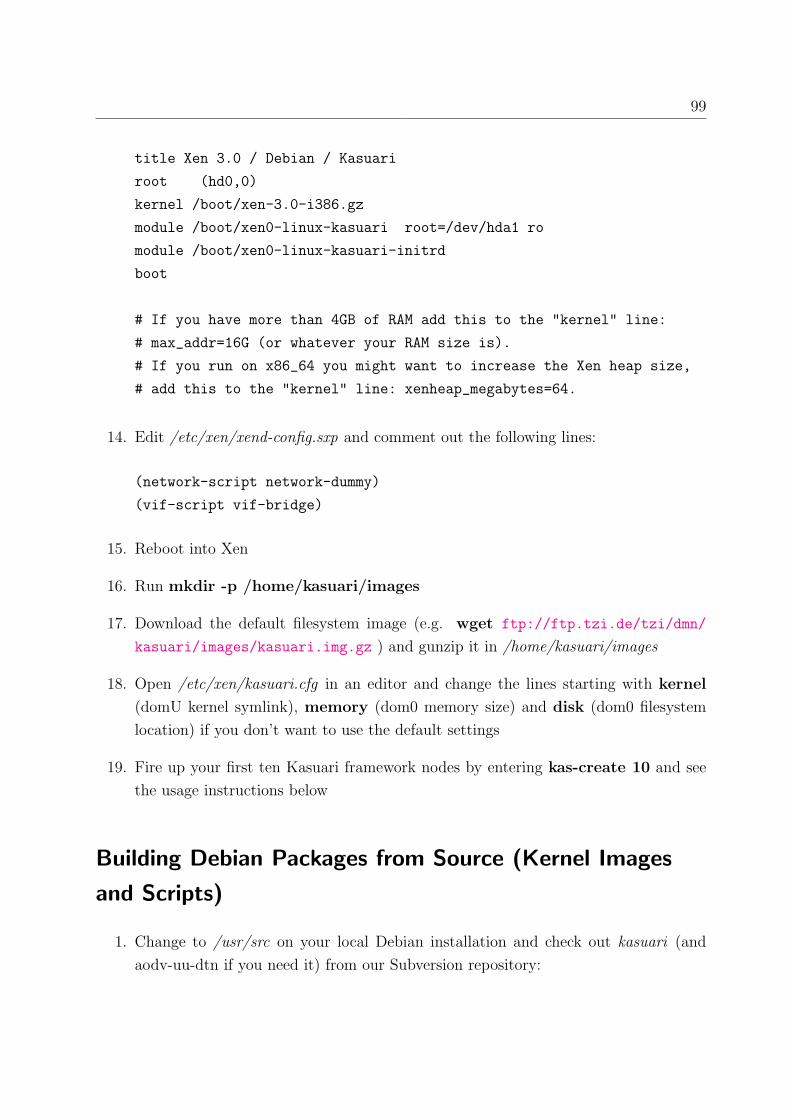
99
title Xen 3.0 / Debian / Kasuari
root (hd0,0)
kernel /boot/xen-3.0-i386.gz
module /boot/xen0-linux-kasuari root=/dev/hda1 ro
module /boot/xen0-linux-kasuari-initrd
boot
# If you have more than 4GB of RAM add this to the "kernel" line:
# max_addr=16G (or whatever your RAM size is).
# If you run on x86_64 you might want to increase the Xen heap size,
# add this to the "kernel" line: xenheap_megabytes=64.
14. Edit /etc/xen/xend-config.sxp and comment out the following lines:
(network-script network-dummy)
(vif-script vif-bridge)
15. Reboot into Xen
16. Run mkdir -p /home/kasuari/images
17. Download the default filesystem image (e.g. wget ftp://ftp.tzi.de/tzi/dmn/
kasuari/images/kasuari.img.gz ) and gunzip it in /home/kasuari/images
18. Open /etc/xen/kasuari.cfg in an editor and change the lines starting with kernel
(domU kernel symlink), memory (dom0 memory size) and disk (dom0 filesystem
location) if you don’t want to use the default settings
19. Fire up your first ten Kasuari framework nodes by entering kas-create 10 and see
the usage instructions below
Building Debian Packages from Source (Kernel Images
and Scripts)
1. Change to /usr/src on your local Debian installation and check out kasuari (and
aodv-uu-dtn if you need it) from our Subversion repository:

100 Appendix A: Installation Instructions
svn co https://prj.tzi.org/repos/dmn/kasuari/trunk kasuari and
svn co https://prj.tzi.org/repos/dmn/aodv-uu-dtn/trunk aodv-uu-dtn
2. Install some packages required for building: apt-get install dpkg-dev debhelper
ocaml-interp python2.4 kernel-package gcc-4.0 module-assistant libc6-dev
udev
3. Optional: put your maintainer details in /etc/kernel-pkg.conf
4. If you are building the Kasuari packages in a 32bit chroot on a 64bit kernel, make
sure you export ARCH=i386
5. change to /usr/src/kasuari/kernel and run ./build-kpkg.sh 2.6.16 1 (kernel release
2.6.16, target package revision 1)
Installation from Source
Short instructions, for advanced users only:
1. Download Xen from the mercurial repository (using the mercurial Debian package):
hg pull http://xenbits.xensource.com/xen-unstable.hg
2. Check out revision 9697 as used in Debian: hg co -C 9697
3. Check out the kasuari SVN repository as described in the previous section
4. Compile Xen from source according to the instructions on the Xen website after
applying the kernel and Xen patches from Kasuari
5. Install Xen and add the Xen daemon to the Debian startup scripts by running
update-rc.d xend defaults
6. Configure the bootloader to boot Xen and reboot
7. Run make install in the Kasuari source directory to install the scripts locally
8. Run mkdir -p /home/kasuari/images
9. Download the default filesystem image (e.g. wget ftp://ftp.tzi.de/tzi/dmn/
kasuari/images/kasuari.img.gz ) and gunzip it in /home/kasuari/images

101
10. Edit the Kasuari scripts to match your domU kernel name, location and initrd image
11. Now you should be able to start Kasuari framework nodes as described in the “Usage”
section below
Nsemulation Installation on Debian GNU/Linux sid
(unstable)
Nsemulation is an emulation-optimised ns2. Although it is not necessary for the Kasuari
framework, it is highly recommended to simulate a realistic network between the virtual
nodes.
1. add our nsemulation mirror to your /etc/apt/sources.list :
deb ftp://ftp.tzi.de/tzi/dmn/kasuari/nse-mirror sid ns2
deb-src ftp://ftp.tzi.de/tzi/dmn/kasuari/nse-mirror sid ns2
2. run apt-get update; apt-get install ns nam
Nsemulation Installation from Source
Please see the instructions in this document: http://www-ivs.cs.uni-magdeburg.de/
EuK/forschung/projekte/nse/howtos/ns2uml userguide.pdf
Usage
� To create virtual machines, run kas-create <number of machines> . The nodes
will be started sequentially, as parallel execution may lead to Xen / cowloop crashes.
� To shut them down, run kas-destroy . This will shut down all VMs in sequence.
The Xen command xm shutdown -a for parallel shutdown may lead to a system
crash, so avoid it.

102 Appendix A: Installation Instructions
� To attach to a VM’s terminal, run xm console kasuariX (replace X with actual
machine number). No login is necessary here.
� By default, each VM has two virtual network interfaces, with IP addresses 10.0.0.X
(eth0) and and 10.0.1.X (eth1) (X is the machine number). The eth0 device can be
connected to a network simulator (nsemulation) or a Linux bridge. The eth1 device is
connected to a Linux bridge (xenbr1) on the dom0. A default gateway to 10.0.1.254
is configured, which is the address of the xenbr1 bridge on dom0. By setting up NAT
on dom0, the xenbr1 device can be used as an Internet gateway for the nodes.
� Live network simulation and visualisation: if nsemulation is installed, start X, open
a terminal window, navigate to /usr/share/doc/kasuari/examples/nse and run nse
10moving.tcl . Edit the Tcl script if you want to change simulation parameters
(number of nodes, field size, duration, 802.11 parameters etc.). Use setdest (source
code included in the nsemulation source package) to create random walk scenarios.
� Alternatively, the network devices can be interconnected by a Linux software bridge
(create one using brctl ) and apply netfilter rules (using the iptables command) or
netem settings (using the tc command) to emulate network conditions like link breaks,
packet loss, delay, etc. See the man pages of the tools mentioned here to find out
about their capabilities and the exact syntax.
� To modify the preconfigured node filesystem, mount the image locally:
mount -o loop /home/kasuari/images/kasuari.img /mnt/loop and use
chroot /mnt/loop to install or uninstall Debian packages there. Beware: some
packages need a mounted /dev and /proc filesystem, some may attempt to start/stop
services on the host machine. Also make sure there is enough free space in the
filesystem, if not, create an empty file with the desired filesystem size, format it to
ext3 and copy the contents of the old filesystem to the new one.
� You can also ssh to the nodes from the host system. A password is required here, in
the default Kasuari Debian image it is “secret”.

Glossary
Ad-Hoc On Demand Distance Vector (AODV) Routing protocol is intended for use by
mobile nodes in an ad hoc network. It offers quick adaptation to dynamic link condi-
tions, low processing and memory overhead, low network utilization, and determines
unicast routes to destinations within the ad hoc network. Routes are determined
on demand only, there is no proactive propagation of routing information. It uses
destination sequence numbers to ensure loop freedom at all times, avoiding problems
(such as ”counting to infinity”) associated with classical distance vector protocols1.
Bash is a Unix shell written for the GNU Project. It is the default shell on most Linux
systems as well as on Mac OS X Tiger, and it can be run on most Unix-like operating
systems2. A sequential list of bash commands in a file is called a bash script.
Debian GNU/Linux is a free operating system that currently uses the Linux kernel. It
comes with over 15490 packages (precompiled software that is bundled up in a nice
format for easy installation) — all of it Free Software. Debian is famous for its
powerful package management system and is in widespread use on many different
hardware platforms3.
Delay Tolerant Networking (DTN) is a network architecture and application interface
structured around optionally-reliable asynchronous message forwarding, with limited
expectations of end-to-end connectivity and node resources. The architecture oper-
ates as an overlay above the transport layers of the networks it interconnects, and
provides key services such as in-network data storage and retransmission, interop-
erable naming, authenticated forwarding and a coarse-grained class of service. It is
mainly used to allow for communications in IP networks with long delay paths and
frequent partitions4.
1Based on [PBD03]2Taken from http://en.wikipedia.org/wiki/Bash3Based on http://www.us.debian.org/intro/about4Taken from [Fall03]
103

104 Glossary
Emulation refers to the ability of a program or device to imitate another program or
device. Unlike simulation, which only attempts to reproduce program or device
behavior, emulation attempts to model to various degrees the state of the program
or device being emulated. Emulation is usually very resource demanding, as most or
all program calls need to be translated before they can be executed5.
Free Software as defined by the Free Software Foundation6, is software which can be used,
copied, studied, modified and redistributed with little or no restriction. Freedom from
such restrictions is central to the concept, with the opposite of free software being
proprietary software (a distinction unrelated to whether a fee is charged). The usual
way for software to be distributed as free software is for the software to be licensed
to the recipient with a free software license such as the GPL (or be in the public
domain), and the source code of the software to be made available (for a compiled
language)7. Free Software is not the same as Open Source Software, it is rather a
subset of it. Open Source does not say anything about the terms and conditions it
is released under.
GNU General Public License (GPL) is a widely used free software license, originally
written by Richard Stallman for the GNU project. The GPL grants the recipients
of a computer program the rights of the Free Software definition and uses copyleft
to ensure the freedoms are preserved, even when the work is changed or added to.
The GPL does not give the licensee unlimited redistribution rights. The right to
redistribute is granted only if the includes the source code and be licensed under the
terms of the GPL. This requirement is known as copyleft8.
Hypervisor see Virtual Machine Monitor
Kasuari is the indonesian word for cassowary, a large, flightless bird found in parts of New
Guinea and Australia. It is related to the emu, another Australian big bird. The
framework presented in this thesis also resembles an emu(lator).
Mobile Ad-Hoc Network (MANET) is a kind of wireless ad-hoc network, and is a self-
configuring network of mobile routers (and associated hosts) connected by wireless
links — the union of which form an arbitrary topology. The routers are free to move
5Based on http://en.wikipedia.org/wiki/Emulation6http://www.fsf.org/licensing/essays/free-sw.html7Taken from http://en.wikipedia.org/wiki/Free software8Taken from http://en.wikipedia.org/wiki/Gpl

Glossary 105
randomly and organise themselves arbitrarily; thus, the network’s wireless topology
may change rapidly and unpredictably. Such a network may operate in a standalone
fashion, or may be connected to the larger Internet9.
Markov chain is a discrete-time stochastic process with the Markov property. A Markov
chain describes at successive times the states of a system. At these times the system
may have changed from the state it was in the moment before to another state, or it
may have stayed in the same state. The changes of state are called transitions. The
Markov property means that the conditional probability distribution of the state in
the future, given the state of the process currently and in the past, depends only on
its current state and not on its state in the past10.
Network Emulation is a technique where the properties of an existing, planned and/or
non-ideal network are simulated in order assess performance, predict the impact of
change, or otherwise optimize technology decision-making. This can be accomplished
by introducing a device on the LAN that alters packet flow in a way that imitates
the behavior of application traffic in the environment being emulated. A network
simulator may also be used in conjunction with live applications and services in
order to emulate a complex network11.
Network Simulation is a technique where a program simulates the behavior of a network.
The program performs this simulation by calculating the interaction between the
different network entities (hosts/routers, data links, packets, etc.) using mathemat-
ical models. In computer science, discrete event simulators are commonly used. In
a discrete event simulator, the state is only calculated at actual events rather than
continuously as in a continuos simulator12.
Simulation is an attempt to model a real-life situation on a computer so that it can be
studied to see how the system works. By changing variables, predictions may be made
about the behaviour of the system. The goal is to calculate the anticipated system
behaviour with mathematical methods as accurately as possible without emulating
the devices or programs used in the real-life situation13.
9Taken from http://en.wikipedia.org/wiki/Mobile ad-hoc network10Taken from http://en.wikipedia.org/wiki/Markov chains11Based on http://en.wikipedia.org/wiki/Network emulation12Based on http://en.wikipedia.org/wiki/Network simulation13Based on http://en.wikipedia.org/wiki/Simulation

106 Glossary
Tcpdump is a common computer network debugging tool that runs under the command
line of various operating systems. It allows the user to intercept and display packets
or frames being transmitted or received over a network to which the computer is
attached. The captured traffic can be stored in a trace file for further analysis with
a tool like Wireshark 14.
Virtualisation is a technique for hiding the physical characteristics of computing resources
from the way in which other systems, applications, or end users interact with those
resources. This includes making a single physical resource (such as a server, an oper-
ating system, an application, or storage device) appear to function as multiple logical
resources; or it can include making multiple physical resources (such as storage de-
vices or servers) appear as a single logical resource. Commonly virtualized resources
include computing power and data storage15.
Virtual Machine Monitor or hypervisor is a scheme that allows multiple operating sys-
tems to run on a host computer at the same time. The hypervisor is a layer between
the operating system and the actual system hardware that simulates I/O interfaces
and schedules concurrent hardware access. An alternative approach requires that
the guest operating system is modified to make system calls directly to the hypervi-
sor, rather than executing machine I/O instructions which are then simulated by the
hypervisor. This is called paravirtualization in Xen16.
Wireshark is a network protocol analyzer that is able to capture and display packet and
frame contents from a live network or a trace file. It is able to identify a large amount
of common network protocols and displays their data fields in a Graphical User
Interface (GUI). Wireshark also supports advanced filtering methods and statistical
traffic analysis. Tshark is the command line version of Wireshark.
14Based on http://en.wikipedia.org/wiki/Tcpdump15Taken from http://en.wikipedia.org/wiki/Virtualisation16Based on http://en.wikipedia.org/wiki/Hypervisor

Bibliography
[ACO97] M. Allman; A. Caldwell; S. Ostermann. ONE: The Ohio Network Emulator.
Technical Report TR-19972. Ohio University, Athens, OH, USA. August 1997.
[BDF+03] Barham; Dragovic; Fraser; Hand; Harris; Ho; Neugebauer; Pratt; Warfield.
Xen and the Art of Virtualization. Proceedings of the 19th ACM Symposium
on Operating Systems Principles (SOSP 2003). Bolton Landing, New York,
NY, USA. October 2003.
[BEF+05] Lee Breslau; Deborah Estrin; Kevin Fall; Sally Floyd; John Heidemann;
Ahmed Helmy; Polly Huang; Steven McCanne; Kannan Varadhan; Ya Xu;
Haobo Yu. Advances in Network Simulation. IEEE Computer 33 (5), pp.
59-67. Washington, DC, USA. May 2000.
[BFM05] T. Berners-Lee; R. Fielding; L. Masinter. Uniform Resource Identifier (URI):
Generic Syntax. RFC 3986. IETF. January 2005.
[BGJL06] John Burgess; Brian Gallagher; David Jensen; Brian Neil Levine. Max-
Prop: Routing for Vehicle-Based Disruption-Tolerant Networks. Proceedings
of IEEE Infocom. Barcelona, Spain. April 2006.
[BSA03] Fan Bai; Narayanan Sadagopan; Ahmed Helmy. IMPORTANT: A framework
to systematically analyze the Impact of Mobility on Performance of Rout-
ing protocols for Adhoc Networks. Proceedings of IEEE Infocom 2003. San
Francisco, CA, USA. March 2003.
[Bul01] C. Bullard. Remote Packet Capture. INTERNET-DRAFT draft-bullard-
pcap-01. IETF. March 2001.
[CBH+06] V. Cerf; S. Burleigh; A. Hooke; L. Torgerson; R. Durst; K. Scott; K. Fall; H.
Weiss. Delay Tolerant Network Architecture. INTERNET-DRAFT draft-irtf-
dtnrg-arch-07. IRTF. March 2006.
107

108 Bibliography
[CS03] Mark Carson; Darrin Santay. NIST Net: a Linux-based Network Emulation
Tool. ACM SIGCOMM Computer Communication Review, Volume 33, Issue
3, pp. 111 -126. Karlsruhe, Germany. July 2003.
[Dike05] J. Dike. A User-Mode Port of the Linux Kernel. 5th Annual Linux Showcase
& Conference. Oakland, California. 2001.
[EFSH04] M. Engel; B. Freisleben; M. Smith; S. Hanemann. Wireless Ad-Hoc Network
Emulation Using Microkernel-Based Virtual Linux Systems. Proceedings of
the 5th EUROSIM Congress on Modeling and Simulation, pp. 198-203. Marne
la Vallee, France. 2004.
[EHH+99] Deborah Estrin; Mark Handley; John Heidemann; Steven McCanne; Ya Xu;
Haobo Yu. Network Visualization with the VINT Network Animator Nam.
Technical Report 99-703b. University of Southern California, CA, USA. March
1999.
[Fall99] Kevin Fall. Network Emulation in the Vint/NS Simulator. Proceedings IEEE
ISCC99. Sharm El Sheik, Red Sea, Egypt. July 1999.
[Fall03] Kevin Fall. A Delay-Tolerant Network Architecture for Challenged Internets.
Proceedings of ACM SIGCOMM 2003. Karlsruhe, Germany. August 2003
[Hem05] Stephen Hemminger. Network Emulation with NetEm. linux.conf.au 2005.
Canberra, Australia. April 2005.
[JoL05] David Johnson; Jay Lepreau. Real Mobility, Real Wireless: A New Kind of
Testbed. The Utah Teapot. The University of Utah, Salt Lake City, UT, USA.
Summer 2005.
[KCC04] S. Kurkowski; T. Camp; M. Colagrosso. A Visualization and Animation Tool
for NS-2 Wireless Simulations: iNSpect. Technical Report MCS-04-03. The
Colorado School of Mines, Golden, CO, USA. June 2004.
[KCC05] Stuart Kurkowski; Tracy Camp; Michael Colagrosso. MANET Simulation
Studies: The Incredibles. ACM SIGMOBILE Mobile Computing and Com-
munications Review Volume 9, Issue 4. ACM Press. New York, NY, USA.
October 2005.

Bibliography 109
[KGM+01] M. Kojo; A. Gurtov; J. Mannner; P. Sarolahti; T. Alanko; K. Raatikainen.
Seawind: a wireless network emulator. Submitted to MMB 2001. Helsinki,
Finland. 2001.
[LD06] A. Lindgren; A. Doria. Probabilistic Routing Protocol for Intermittently
Connected Networks. INTERNET-DRAFT draft-lindgren-dtnrg-prophet-02.
IETF. March 2006.
[Loo05] Kevin Loos. Papageno: Eine skalierbare Distributionsplattform fur heterogene
Empfangergruppen. Diploma thesis. Universitat Bremen. 2005.
[LPP+05] Kun-chan Lan; Eranga Perera; Henrik Petander; Christoph Dwertmann; Lavy
Libman; Mahbub Hassan. MOBNET: The Design and Implementation of a
Network Mobility Testbed for NEMO Protocol. 14th IEEE Workshop on Local
and Metropolitan Area Networks(LANMAN 2005). Chania, Island of Crete,
Greece. September 2005.
[MBLD05] Michael Matthes; Holger Biehl; Michael Lauer; Oswald Drobnik. MASSIVE:
An Emulation Environment for Mobile Ad-hoc Networks. Proceedings of the
Second Annual Conference on Wireless On-demand Network Systems and Ser-
vices (WONS 2005). St. Moritz, Switzerland. 2004.
[MI4] Daniel Mahrenholz; Svilen Ivanov. Real-Time Network Emulation with ns-2.
Proceedings of The 8-th IEEE International Symposium on Distributed Sim-
ulation and Real Time Applications. Budapest, Hungary. October 2004.
[OK05] Jorg Ott; Dirk Kutscher. A Disconnection-Tolerant Transport for Drive-thru
Internet Environments. Proceedings of Infocom 2005. Miami, FL, USA. March
2005.
[OK05-TR] Jorg Ott; Dirk Kutscher. Applying DTN to Mobile Internet Access: An Ex-
periment with HTTP. Technical Report TR-TZI-050701. Universitat Bremen,
Germany. July 2005.
[OKD06] Jorg Ott; Dirk Kutscher; Christoph Dwertmann. Integrating DTN and
MANET Routing. ACM SIGCOMM Workshop on Challenged Networks
(CHANTS 2006). Pisa, Italy. September 2006.
[PBD03] C. Perkins; E. Belding-Royer; S. Das. Ad hoc On-Demand Distance Vector
(AODV) Routing. RFC 3561. IETF. July 2003.

110 Bibliography
[PP05] Matija Puzar; Thomas Plagemann. NEMAN: A Network Emulator for Mo-
bile Ad-Hoc Networks. 8th International Conference on Telecommunications
(ConTEL 2005). Zagreb, Croatia. June 2005.
[PWWM05] M. Petrova; L. Wu; M. Wellens; P. Mahonen. Hop of No Return: Practi-
cal Limitations of Wireless Multi-Hop Networking. Proceedings of RealMAN
2005. Santorini, Greece. July 2005.
[SB06] K. Scott; S. Burleigh. Bundle Protocol Specification. INTERNET-DRAFT
draft-irtf-dtnrg-bundle-spec-06. IETF. August 2006.
[SBU00] Rob Simmonds; Russell Bradford; Brian Unger. Applying parallel discrete
event simulation to network emulation. Proceedings of the 14th Workshop on
Parallel and Distributed Simulation. Bologna, Italy. May 2000.
[VB00] A. Vahdat; D. Becker. Epidemic routing for partially connected ad hoc net-
works. Technical Report CS-200006. Duke University, Durham, NC, USA.
April 2000.
[VYW+02] Amin Vahdat; Ken Yocum; Kevin Walsh; Priya Mahadevan; Dejan Kostic;
Jeff Chase; David Becker. Scalability and Accuracy in a Large-Scale Network
Emulator. 5th Symposium on Operating System Design and Implementation
(OSDI 2002). Boston, MA, USA. December 9-11, 2002.
[Zim06] Dennis Zimmer. Professionelle Virtualisierungsprodukte: Ein Uberblick. iX
Magazin 5/2006 pp. 64-70. Heise Zeitschriften Verlag. Hannover, Germany.
May 2006.
[ZL02] Yongguang Zhang; Wei Li. An integrated environment for testing Mobile Ad-
Hoc Networks. Proceedings of MobiHoc 2002. Lausanne, Switzerland. June
2002.