Embed Size (px)
DESCRIPTION
paper
Citation preview
A survey on control of electric power distributed generation systemsfor microgrid applications
Allal M. Bouzid a,b,n, Josep M. Guerrero c, Ahmed Cheriti b, Mohamed Bouhamida a,Pierre Sicard b, Mustapha Benghanem a
a Department of Electrical Engineering, Université des Sciences et de la Technologie d'Oran, Algeriab Department of Electrical and Computer Engineering Université du Québec à Trois-Rivières (Québec), Canadac Department of Energy Technology, Aalborg University, Aalborg East 9220, Denmark
a r t i c l e i n f o
Article history:Received 18 June 2014Received in revised form13 December 2014Accepted 4 January 2015Available online 28 January 2015
Keywords:Distributed power generation system(DPGS)Hierarchical controlGrid-formingGrid-feedingGrid-supporting.
a b s t r a c t
The introduction of microgrids in distribution networks based on power electronics facilitates the use ofrenewable energy resources, distributed generation (DG) and storage systems while improving thequality of electric power and reducing losses thus increasing the performance and reliability of theelectrical system. The hierarchical control structure, which consists of primary, secondary, and tertiarylevels for microgrids that mimic the behavior of the mains grid, is reviewed. The main objective of thisarticle is to give a description of state of the art for distributed power generation systems (DPGS) basedon renewable energy and explore the power converters connected in parallel to the grid which aredistinguished by their contribution to the formation of the grid voltage and frequency and areaccordingly classified in three classes. This analysis is extended focusing mainly on the three classesof configurations: grid-forming, grid-feeding, and grid-supporting. The article ends up with an overviewand a discussion of the control structures and strategies to control distribution power generation system(DPGS) units connected to the network.
& 2015 Elsevier Ltd. All rights reserved.
Contents
1. Introduction . . . . . . . . . . . . . . . . . . . . . . . . . . . . . . . . . . . . . . . . . . . . . . . . . . . . . . . . . . . . . . . . . . . . . . . . . . . . . . . . . . . . . . . . . . . . . . . . . . . . . . . . 7522. Introduction to microgrids . . . . . . . . . . . . . . . . . . . . . . . . . . . . . . . . . . . . . . . . . . . . . . . . . . . . . . . . . . . . . . . . . . . . . . . . . . . . . . . . . . . . . . . . . . . . 753
2.1. Energy storage system. . . . . . . . . . . . . . . . . . . . . . . . . . . . . . . . . . . . . . . . . . . . . . . . . . . . . . . . . . . . . . . . . . . . . . . . . . . . . . . . . . . . . . . . . . 7543. Structure of distributed power generation . . . . . . . . . . . . . . . . . . . . . . . . . . . . . . . . . . . . . . . . . . . . . . . . . . . . . . . . . . . . . . . . . . . . . . . . . . . . . . . . 7544. Overview and design of the hierarchical control of microgrid . . . . . . . . . . . . . . . . . . . . . . . . . . . . . . . . . . . . . . . . . . . . . . . . . . . . . . . . . . . . . . . . 755
4.1. Primary control (droop control) . . . . . . . . . . . . . . . . . . . . . . . . . . . . . . . . . . . . . . . . . . . . . . . . . . . . . . . . . . . . . . . . . . . . . . . . . . . . . . . . . . 7554.2. Secondary control (frequency and voltage restoration and synchronization) . . . . . . . . . . . . . . . . . . . . . . . . . . . . . . . . . . . . . . . . . . . . . . . 7564.3. Tertiary control (P-Q import and export) . . . . . . . . . . . . . . . . . . . . . . . . . . . . . . . . . . . . . . . . . . . . . . . . . . . . . . . . . . . . . . . . . . . . . . . . . . . 756
5. Classification of outer control loops for DPGS according to their role in microgrids . . . . . . . . . . . . . . . . . . . . . . . . . . . . . . . . . . . . . . . . . . . . . . . 7565.1. Control of grid-forming power converters . . . . . . . . . . . . . . . . . . . . . . . . . . . . . . . . . . . . . . . . . . . . . . . . . . . . . . . . . . . . . . . . . . . . . . . . . . 7565.2. Control of grid-feeding power converters . . . . . . . . . . . . . . . . . . . . . . . . . . . . . . . . . . . . . . . . . . . . . . . . . . . . . . . . . . . . . . . . . . . . . . . . . . 7565.3. Control of grid-supporting power converters. . . . . . . . . . . . . . . . . . . . . . . . . . . . . . . . . . . . . . . . . . . . . . . . . . . . . . . . . . . . . . . . . . . . . . . . 757
Contents lists available at ScienceDirect
journal homepage: www.elsevier.com/locate/rser
Renewable and Sustainable Energy Reviews
http://dx.doi.org/10.1016/j.rser.2015.01.0161364-0321/& 2015 Elsevier Ltd. All rights reserved.
Abbreviations: AC, Alternating current; CHP, Combined heat and power; DB, Deadbeat; DC, Direct current; DER, Distributed energy resources; DG, Distributed generation;DPC, Direct power control; DPGS, Distributed power generation systems; dq, Park transformation; EES, Electrical energy storage; FACTS, Flexible AC transmission system; FIR,Finite impulse response; HC, Harmonic compensator; HES, Hybrid Energy System; ILC, Iterative learning control; IMP, Internal model principle; IRSMC, Integral resonantsliding mode controller; LQ, Linear quadratic; LQG, Linear Quadratic Gaussian; LQR, Linear Quadratic Regulator; MG, Microgrid; NPC, Neutral-point-clamped; NN, Neuralnetwork; NNIPI, Neural network interfacing-parameters identifier; NNGVE, Neural network grid-voltage estimator; PI, Proportional integral; PID, Proportional integralderivative; PR, Proportional resonant; PWM, Pulse width modulation; PCC, Point of common coupling; PED, Power electronics device; RC, Repetitive feedback control; SISO,Single-input single-output; SMC, Sliding mode controller; THD, Total harmonic distortion; UPS, Uninterruptible power supply; VPP, Virtual power plants; VSC, Voltage-source converters
n Corresponding author at: Department of Electrical and Computer Engineering Université du Québec à Trois-Rivières (Québec), Canada. Tel.: þ1 819 701 0827.E-mail addresses: [email protected], [email protected] (A.M. Bouzid).
Renewable and Sustainable Energy Reviews 44 (2015) 751–766
5.3.1. Grid supporting power converter operating as a voltage source. . . . . . . . . . . . . . . . . . . . . . . . . . . . . . . . . . . . . . . . . . . . . . . . . . 7575.3.2. Grid supporting power converter operating as a current source. . . . . . . . . . . . . . . . . . . . . . . . . . . . . . . . . . . . . . . . . . . . . . . . . . 757
6. Overview of inner control loops for DPGS . . . . . . . . . . . . . . . . . . . . . . . . . . . . . . . . . . . . . . . . . . . . . . . . . . . . . . . . . . . . . . . . . . . . . . . . . . . . . . . . 7586.1. Classical PID control . . . . . . . . . . . . . . . . . . . . . . . . . . . . . . . . . . . . . . . . . . . . . . . . . . . . . . . . . . . . . . . . . . . . . . . . . . . . . . . . . . . . . . . . . . . 7586.2. Proportional resonant (PR) . . . . . . . . . . . . . . . . . . . . . . . . . . . . . . . . . . . . . . . . . . . . . . . . . . . . . . . . . . . . . . . . . . . . . . . . . . . . . . . . . . . . . . 7586.3. Predictive control. . . . . . . . . . . . . . . . . . . . . . . . . . . . . . . . . . . . . . . . . . . . . . . . . . . . . . . . . . . . . . . . . . . . . . . . . . . . . . . . . . . . . . . . . . . . . . 7586.4. Dead-beat control . . . . . . . . . . . . . . . . . . . . . . . . . . . . . . . . . . . . . . . . . . . . . . . . . . . . . . . . . . . . . . . . . . . . . . . . . . . . . . . . . . . . . . . . . . . . . 7596.5. Hysteresis control . . . . . . . . . . . . . . . . . . . . . . . . . . . . . . . . . . . . . . . . . . . . . . . . . . . . . . . . . . . . . . . . . . . . . . . . . . . . . . . . . . . . . . . . . . . . . 7596.6. LQG/LQR . . . . . . . . . . . . . . . . . . . . . . . . . . . . . . . . . . . . . . . . . . . . . . . . . . . . . . . . . . . . . . . . . . . . . . . . . . . . . . . . . . . . . . . . . . . . . . . . . . . . . 7596.7. Sliding mode controls . . . . . . . . . . . . . . . . . . . . . . . . . . . . . . . . . . . . . . . . . . . . . . . . . . . . . . . . . . . . . . . . . . . . . . . . . . . . . . . . . . . . . . . . . . 7596.8. H1 controllers. . . . . . . . . . . . . . . . . . . . . . . . . . . . . . . . . . . . . . . . . . . . . . . . . . . . . . . . . . . . . . . . . . . . . . . . . . . . . . . . . . . . . . . . . . . . . . . . 7596.9. Repetitive controller (RC) . . . . . . . . . . . . . . . . . . . . . . . . . . . . . . . . . . . . . . . . . . . . . . . . . . . . . . . . . . . . . . . . . . . . . . . . . . . . . . . . . . . . . . . 7606.10. Neural networks and fuzzy control methods . . . . . . . . . . . . . . . . . . . . . . . . . . . . . . . . . . . . . . . . . . . . . . . . . . . . . . . . . . . . . . . . . . . . . . . . 760
7. Review of software tools . . . . . . . . . . . . . . . . . . . . . . . . . . . . . . . . . . . . . . . . . . . . . . . . . . . . . . . . . . . . . . . . . . . . . . . . . . . . . . . . . . . . . . . . . . . . . . 7607.1. Optimization software tools . . . . . . . . . . . . . . . . . . . . . . . . . . . . . . . . . . . . . . . . . . . . . . . . . . . . . . . . . . . . . . . . . . . . . . . . . . . . . . . . . . . . . 7617.2. Simulation and real-time implementation platforms. . . . . . . . . . . . . . . . . . . . . . . . . . . . . . . . . . . . . . . . . . . . . . . . . . . . . . . . . . . . . . . . . . 761
8. Discussion and conclusion . . . . . . . . . . . . . . . . . . . . . . . . . . . . . . . . . . . . . . . . . . . . . . . . . . . . . . . . . . . . . . . . . . . . . . . . . . . . . . . . . . . . . . . . . . . . 763References . . . . . . . . . . . . . . . . . . . . . . . . . . . . . . . . . . . . . . . . . . . . . . . . . . . . . . . . . . . . . . . . . . . . . . . . . . . . . . . . . . . . . . . . . . . . . . . . . . . . . . . . . . . . . 763
1. Introduction
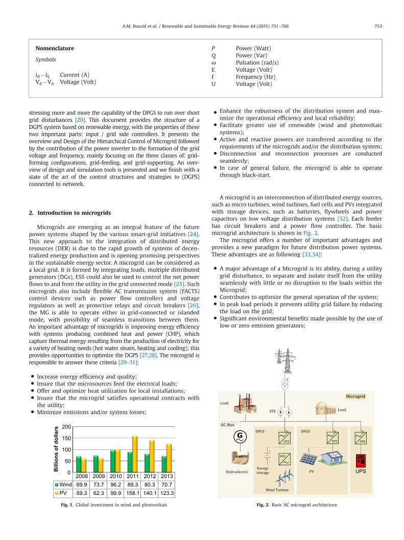
Today, there is an increasing use of small-scale renewable powersources into modern electric grids, because the current growingdemand for electrical energy [1,2]. Photovoltaics, wind power andhydroelectric power are three of the renewable energies that aremostly used; they are clean for the environment and inexhaustible.This renewable energy has experienced rapid technological develop-ment, which makes them at affordable prices. This advantage allowsthe energy security of countries to reduce imports of fossil fuels, whichallows maintaining a lower cost than usual prices and improves thestandard of living without harming the environment, especially in atime when the economic crisis is timely. Another advantage, they caneasily support the electrical network in remote sites and rural areas[2]. As shown in Fig. 1, the rate of investment of wind energy wasmore important in 2010, but it started dropping in 2011, 2012 and2013 in contrast to the solar energy that has experienced the sameproblem a year later compared to wind power. Despite the economicproblems many countries support programs connecting renewableenergy with global and local power grid. In order to integrate differentkinds of renewable energy sources, the concept of microgrid (MG) wasproposed several years ago [3]. A microgrid can be defined as a part ofthe grid consisting of prime energy movers, power electronics con-verters, distributed energy storage systems, and local loads [4].
This makes the electrical network more flexible and intelligent [5].Microgrids and virtual power plants (VPPs) are two low voltagedistribution network concepts that can participate in active networkmanagement of a smart grid [6,7]. They are becoming an importantconcept to integrate distributed generation (DG) and energy storagesystems [5,8]. The interest of DG grows and is taking importance [9]when it is composed of different energy resources: Photovoltaics, windpower and hydroelectric power with electrical energy storage (EES) (e.g., batteries or super capacitors) [6] forming a Hybrid Energy System(HES) [2], because they can easily support the electrical network inisland mode and rural areas or grid- connection mode. Other non-renewable based power systems (diesel or gas), whose generationprofile can be easily controlled are also likely to be integrated intomicrogrids [10]. This gives the user the possibility to produce and storepart of the electrical power of the whole system [9]. The use of DPGSmakes no sense without using distributed storage systems to copewith the energy balances [5]. Microgrids should be able to locally solveenergy problems and hence increase flexibility [11]. The advancecarried in recent years in power electronics makes this latter veryattractive when integrating renewable energy resources, distributedenergy storage systems and active loads [4,12]. The Power Electronic
Converters are typically used as interfaces between these devices andthe MG, acting as a voltage source (voltage source inverter VSI, in thecase of AC network micro) [3,8,12]. MGs need to be able to operateintelligently in both grid and island mode [13]. At the same time, ACand DC sources sometimes coexist in a practical microgrid. Theinterfacing converters are usually connected in parallel [3]. The controlof the parallel VSIs forming a MG has been investigated in the lastyears [12]. Thus, the greatest challenge is to ensure stability andvoltage regulation for offering a better power quality for the customer[9]. In order to avoid circulating currents among the converterswithout using any critical communication between them, the droop-control method is often applied [5,11]. This is a kind of collaborativecontrol used for sharing active and reactive power between VSIs in acooperative way [12]. These control loops, also called P�ω and Q�Edroops, have been applied to connect inverters in parallel in unin-terruptible power supply (UPS) systems to avoid mutual control wireswhile obtaining good power sharing [5,11,14,15]. However, althoughthis technique achieves high reliability and flexibility, the price to payis that the sharing is obtained through voltage and frequency devia-tions in the system (load dependent frequency and amplitude devia-tions) [12,16,17], which limit its application [5,11]. In order to solvethese problems, an external control loop named secondary control isimplemented in the microgrid control central to restore the nominalfrequency and amplitude values in the microgrid [4,5,11,12]. Anadditional tertiary control can be used for bidirectional control thepower flow. In case of AC microgrids, the objective is to regulate thepower flows between the grid and the microgrid at the point ofcommon coupling (PCC) [5,11,18,19]. In countries with hydro powerpotential, small hydro turbines are used at the distribution level, inorder to sustain the utility network in dispersed or remote locations[20]. At present time, most of renewable based DG units directlyproduce DC or variable frequency/voltage AC output power and hencepower electronics devices (PEDs) have become the key elements inorder to realize the MGs [21]. But an increased amount of DPGS basedonwind turbine and photovoltaic are connected to the utility networkand can create instability in the power systems because of thevariation of the wind and sun. In order to maintain a stable powersystem in countries with a large penetration of distributed power,transmission system operators issue more stringent demands regard-ing the interconnection of the DPGS to the utility grid [22]. Besidestheir low efficiency, the controllability of the DPGS based on both windand sun are their main drawback [23]. As a consequence, theirconnection to the utility network can lead to grid instability or evenfailure, if these systems are not properly controlled. Moreover, thestandards for interconnecting these systems to the utility network are
A.M. Bouzid et al. / Renewable and Sustainable Energy Reviews 44 (2015) 751–766752
stressing more and more the capability of the DPGS to run over shortgrid disturbances [20]. This document provides the structure of aDGPS system based on renewable energy, with the properties of thesetwo important parts: input / grid side controllers. It presents theoverview and Design of the Hierarchical Control of Microgrid followedby the contribution of the power inverter to the formation of the gridvoltage and frequency, mainly focusing on the three classes of: grid-forming configurations, grid-feeding, and grid-supporting. An over-view of design and simulation tools is presented and we finish with astate of the art of the control structures and strategies to (DGPS)connected to network.
2. Introduction to microgrids
Microgrids are emerging as an integral feature of the futurepower systems shaped by the various smart-grid initiatives [24].This new approach to the integration of distributed energyresources (DER) is due to the rapid growth of systems of decen-tralized energy production and is opening promising perspectivesin the sustainable energy sector. A microgrid can be considered asa local grid. It is formed by integrating loads, multiple distributedgenerators (DGs), ESS could also be used to control the net powerflows to and from the utility in the grid connected mode [25]. Suchmicrogrids also include flexible AC transmission system (FACTS)control devices such as power flow controllers and voltageregulators as well as protective relays and circuit breakers [26],the MG is able to operate either in grid-connected or islandedmode, with possibility of seamless transitions between them.An important advantage of microgrids is improving energy efficiencywith systems producing combined heat and power (CHP), whichcapture thermal energy resulting from the production of electricity fora variety of heating needs (hot water steam, heating and cooling); thisprovides opportunities to optimize the DGPS [27,28]. The microgrid isresponsible to answer these criteria [29–31]:
� Increase energy efficiency and quality;� Insure that the microsources feed the electrical loads;� Offer and optimize heat utilization for local installations;� Insure that the microgrid satisfies operational contracts with
the utility;� Minimize emissions and/or system losses;
� Enhance the robustness of the distribution system and max-imize the operational efficiency and local reliability;
� Facilitate greater use of renewable (wind and photovoltaicsystems);
� Active and reactive powers are transferred according to therequirements of the microgrids and/or the distribution system;
� Disconnection and reconnection processes are conductedseamlessly;
� In case of general failure, the microgrid is able to operatethrough black-start.
A microgrid is an interconnection of distributed energy sources,such as micro turbines, wind turbines, fuel cells and PVs integratedwith storage devices, such as batteries, flywheels and powercapacitors on low voltage distribution systems [32]. Each feederhas circuit breakers and a power flow controller. The basicmicrogrid architecture is shown in Fig. 2.
The microgrid offers a number of important advantages andprovides a new paradigm for future distribution power systems.These advantages are as following [33,34]:
� A major advantage of a Microgrid is its ability, during a utilitygrid disturbance, to separate and isolate itself from the utilityseamlessly with little or no disruption to the loads within theMicrogrid;
� Contributes to optimize the general operation of the system;� In peak load periods it prevents utility grid failure by reducing
the load on the grid;� Significant environmental benefits made possible by the use of
low or zero emission generators;
Fig. 2. Basic AC microgrid architecture
Nomenclature
Symbols
id� iq Current (A)Vd�Vq Voltage (Volt)
P Power (Watt)Q Power (Var)ω Pulsation (rad/s)E Voltage (Volt)f Frequency (Hz)U Voltage (Volt)
2008 2009 2010 2011 2012 2013Wind 69.9 73.7 96.2 89.3 80.3 70.7PV 59.3 62.3 99.9 158.1 140.1 123.3
0
50
100
150
200
Bill
ions
of d
olla
rs
Fig. 1. Global investment in wind and photovoltaic
A.M. Bouzid et al. / Renewable and Sustainable Energy Reviews 44 (2015) 751–766 753

� The use of both electricity and heat permitted by the closeproximity of the generator to the user, thereby increasing theoverall energy efficiency;
� Microgrid can act to mitigate the electricity costs to its users bygenerating some or all of its electricity needs;
� Enhancing the quality of power which is delivered to sensitiveloads [35].
Despite the fact that the AC microgrid system has a largenumber of benefits, its application involves some problems of lowefficiency and several disadvantages; these very challenging pro-blems are listed below [29,36–41]:
� Major drawbacks to increased DER utilization are� High cost and net metering may pose obstacles for Microgrid;� The need for custom engineering;� Interconnection standards need to be developed to ensure
consistency.� The control and protection hardware are one of the most
important challenges for facing the implementation of Micro-grids and ensure the supplying of the customers in island mode;
� Resynchronization with the utility grid is difficult [37,42]:� The ability to maintain synchronism after transition to
island operation is crucial from stability point of view;� Synchronized reconnection of island operated microgrid
back to utility grid means that the voltage angle differencebetween utility grid and microgrid should be minimizedbefore re-connection in order to prevent voltage distur-bances in the MG.
� The small errors in voltage set points, can create circulatingcurrents that exceed the limits of the Micro source, whichcauses voltage and/or reactive power oscillations. Likewise inisland mode, the need to change power-operating points, forfrequency generation to match load changes, can create pro-blems and slight errors in frequency generation. Henceforth,this makes these parameters (Voltage, frequency and powerquality) very important and they must be considered andcontrolled to acceptable standards.
� The unequal line impedances and DG output impedances signifi-cantly affect the accuracy of reactive power control during grid-connected operation mode and the reactive power sharing duringislanding mode due to the unequal voltage drops[36].
2.1. Energy storage system
The Energy storage devices are one of the main criticalcomponents to rely on for successful operation of a microgrid thatprovides the user with dispatch capability of the distributedresources (PV and wind etc.) and to be the caretaker in balancingthe power and energy demand with generation. It is easier tointegrate into a dc system. The stored energy can then be used toprovide electricity during periods of high demand. Energy storagedevices take this responsibility in three necessary scenarios[24]:
� Insure the power balance in a microgrid despite load fluctua-tions and transients since DGs with their lower inertia lack thecapability for fast responding to these disturbances;
� Provides ride-through capability when there are dynamicvariations in intermittent energy sources and allows the DGsto operate as dispatchable units;
� Provides the initial energy requirement for a seamless transitionbetween grid-connected to/from islanded operation of microgrids.
But its disadvantage is that the electrical energy needs to bestored in battery banks requiring more space and maintenance.
3. Structure of distributed power generation
DG is defined as, “Generation of electricity by facilities that aresufficiently smaller than central generating plants so as to allowinterconnection at nearly any point in the power system”[43,44].The structure of distributed generation power system contains theinput power source, different configurations are possible: photo-voltaic, fuel cell, wind turbine, etc.; the converter which can be asingle-stage converter (DC-AC converter) or a double stage converter(DC-DC and DC-AC converter). They have two separate operationmodes, acting as a current source if they are connected to thegrid and as a voltage source if they work autonomously [9]. Anoutput filter (L, LC, LCL, and LCL with damping resistor) connected inseries with the inverter improves harmonic performance at lowerswitching frequencies [45–50]. Recently, the LCL filter has beenwidely applied to the grid-interfaced inverters [45,51]. The generalstructure having different input power sources is depicted in Fig. 3.The Distribution Generation (DG) unit can be connected to the utilitygrid through single Point of Common Coupling (PCC). It is respon-sible for generation of electricity and it has to be able to import/export energy from/to the grid, control the active and reactive powerflows and manage the energy storage [19].
From Table 1, the main task of the input controller is to extractthe maximum power from the renewable energy sources andprotect the input side converter while, the grid side controllermust check the active and reactive power transferred from renew-able energy systems to the grid.
VSI
C
+-
Vabc
+-
Energystorage
Lf
PCCAC Micro-grid bus
Utility grid
Micro grid
Local load
Wind turbine
PV array
Fuel cell
MPPT Control
Input side controller
Grid side controller
Control the input power
MPPT
Generator speed control
Power control
P*- Q*
Grid monitoring
Line impedance detection
Grid synchronisation
System Monitoring and Control
Grid
Con
ditio
n D
etec
tion
Fig. 3. General structure for distributed power system
A.M. Bouzid et al. / Renewable and Sustainable Energy Reviews 44 (2015) 751–766754

4. Overview and design of the hierarchical control ofmicrogrid
Most current microgrid implementations combine differentdistributed energy resources [18] (PV arrays, small wind turbines,or fuel cells) or storage devices (flywheels, superconductor induc-tors, or compressed air systems) [19,52,53]. However, at thepresent time it is necessary to conceive a flexible microgrid which
should be able to import/export energy from/to the grid (control ofactive and reactive power flow) [19], and with capabilities forstandalone and grid-connected applications [11].
Hierarchical control for microgrids has been proposed recentlyin [4,5,8,11,18,19,54–61] to standardize the microgrid operationand functions. This hierarchical control can be divided into threelevels of control namely primary, secondary and tertiary level,each of these levels has objectives and methods of controllingwhich are designed and manipulated by different controllers[62,63]. Fig. 4 shows the schematic diagram of the hierarchicalarchitecture of a microgrid using these three levels of control.
4.1. Primary control (droop control)
The primary controller is responsible for the reliability andimproving the system performance and stability for the localvoltage control; adjusting at the same time the frequency andthe magnitude of the output voltage to get the reference of innercurrent and voltage control loops; and for ensuring a properpower sharing (active and reactive power among DG units). Eachinverter will have an external power loop based on droop control[60,64], that allows each DG unit to operate autonomously.The primary control is based only on local measurements; com-munication is often avoided for reliability reasons.
Table 1Properties of the Part of the DPGS.
Part of DPGS Property
Input side controller The main property to extract the maximum powerfrom the input source:a) Maximum power point trackingb) Generator speed control
Grid side controller Control of active power generated to the gridControl of reactive power transfer between theDPGS and the gridControl of dc-link voltageGrid synchronizationLine impedance detection
Fig.4. Hierarchical architecture of a microgrid
A.M. Bouzid et al. / Renewable and Sustainable Energy Reviews 44 (2015) 751–766 755
The control of the parallel inverters in DG systems is based on[65–67]:
� the inner voltage and current regulation loops (feedback andfeedforward; linear and nonlinear control loops can be per-formed to regulate and supervise the inductor current or thecapacitor current of the output filter to reach a fast dynamicresponse while maintaining the system stable);
� the intermediate virtual impedance loop (to emulate physicaloutput impedance);
� the outer active and reactive power sharing loops (whosefunction is to regulate the output voltage).
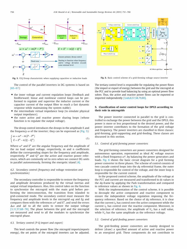
The droop control introduces the droops in the amplitude E andthe frequency ω of the inverter; they can be expressed as (Fig. 5):
ω¼ωn�m P�Pn� �
E¼ En�n Q�Qn� �
(ð1Þ
Where ωn and En are the angular frequency and the amplitude ofthe no load output voltage, respectively, m and n coefficientsdefine the corresponding slopes for the frequency and amplitude,respectively. Pn and Qn are the active and reactive power refer-ences, which are commonly set to zero when we connect DG unitsin parallel autonomously, forming the energetic island [4].
4.2. Secondary control (frequency and voltage restoration andsynchronization)
The secondary controller is responsible to restore the frequencyand amplitude deviations produced by the virtual inertias andoutput virtual impedances. Also, this control takes on the functionto synchronize the microgrid with the main grid before per-forming the interconnection, the transition from islanded togrid-connected mode. The secondary control must measure thefrequency and amplitude levels in the microgrid ωg and Eg andcompares them with the references ωn and En, and send the errorsΔω and ΔE to all the units to restore the output voltage[3,11,57,68–78]. The phase between the grid and the microgridare measured and send to all the modules to synchronize themicrogrid phase.
4.3. Tertiary control (P-Q import and export)
This level controls the power flow (the microgrid imports/exportsenergy), the set points of the microgrid inverters can be adjusted.
The tertiary control level is responsible for regulating the power flows(the import or export of energy) between the grid and themicrogrid atthe PCC and to provide load balancing by using an optimal power flowsolver. Thus, the active and reactive power flows can be exported orimported independently [3,4,6,8,57,58,79,80].
5. Classification of outer control loops for DPGS according totheir role in microgrids
The power inverter connected in parallel to the grid is con-trolled to exchange the power between the grid and the DPGS, thispower is more or less proportional to the desired power, and thepower inverter contributes to the formation of the grid voltageand frequency. The power inverters are classified in three classes:grid-forming, grid-supporting and grid-feeding. These classes arediscussed in this section.
5.1. Control of grid-forming power converters
The grid forming converters are power converters designed forautonomous operation, represented as ideal AC voltage sourceswith a fixed frequency ωn, by balancing the power generators andloads. Fig. 6 shows the basic circuit diagram for a grid formingpower converter in three phases. The scheme of control consists oftwo cascade control loops into the dq referential frame, the outerloop is responsible for control of the voltage, and the inner loop isresponsible for the current control.
In the proposed control scheme, the amplitude of the voltage atthe PCC and current are measured and transformed to dc values inthe dq-frame by applying the Park transformation and comparedto reference values as shown in Fig. 6.
With the implementation of the control scheme, it is possibleto decouple the active component and reactive component toensure the independent voltage regulation imposing the fre-quency reference. Based on the choice of dq reference, it is clearthat the current id has control over the active component while thecurrent iq has control over the reactive component. Moreover, inthe selection of reference, the amplitude of Vq has a null value,while Vd has the same amplitude as the reference voltage.
5.2. Control of grid-feeding power converters
The grid-feeding power converters are mainly designed todeliver (draw) a specified amount of active and reactive powerto an energized grid. These components do not contribute to
E
E
Fig. 5. P/Q Droop characteristic when supplying capacitive or inductive loads Fig. 6. Basic control scheme of a grid-forming voltage source inverter
A.M. Bouzid et al. / Renewable and Sustainable Energy Reviews 44 (2015) 751–766756

power balancing [81]. Grid-feeding power converters are con-trolled in current and can be represented as ideal current sourcesconnected to the grid in parallel and presenting high paralleloutput impedance. These power converters are suitable to operatein parallel with other grid-feeding power converters in grid-connected mode. Actually, most of the power converters belongingto DG systems operate in grid-feeding mode, like in PV or windpower systems [23].
The scheme control of the grid-feeding power converter isdepicted in Fig. 7, where Pn and Qn represent the active and thereactive powers to be delivered, respectively. Control of the outputvoltage is no longer a purpose, and thus the control schemecomprises only the primary current control [81].
The grid-feeding should be perfectly synchronized with the acvoltage at the connection point, in order to regulate accurately theactive and reactive power exchanged with the grid. This is why wemust use phase locked loop. Based on the choice of dq reference, theamplitude of Vq has a null value, while Vd is equal to the amplitude ofthe voltage; the current id has control over the active componentwhile the current iq has control over the reactive component.Henceforth the desired direct id and quadrature iq current componentsare easily derived from the active Pn and reactive Qnpower compo-nents by dividing them by the direct voltage component Ud. Grid-feeding power converters cannot operate in island mode if there is nogrid-forming or grid-supporting power converter, or a local synchro-nous generator, setting the voltage amplitude and frequency of the acmicrogrid [10].
5.3. Control of grid-supporting power converters
Grid-supporting power converters are designed to control theAC grid voltage amplitude En (reactive power) and frequency ωn
(active power) quality of either a stand-alone or interconnectedgrid allowing power sharing for to power balancing. They supporta grid, either alone or with other grid-supporting inverters. Thereare two main types of power converters in the grid-supporting,those controlled as a voltage source with link impedance, or asa current source with parallel impedance. In grid-supportinginverters, the circulating currents between two paralleled grid-forming inverters are avoided by introducing artificial droopcoefficients in the inverter frequency and voltage control, equiva-lent to the droop of the generator in the primary frequency control
of synchronous generators in the utility grid [81]:
f � f 0 ¼ �kp P�P0ð ÞU�U0 ¼ �kq Q�Q0ð Þ
(: ð2Þ
5.3.1. Grid supporting power converter operating as a voltage sourceThe power converter is based on the control scheme of a grid-
supporting inverter as shown in Fig. 8. There it is controlled foremulating the behavior of an AC voltage source connected to thegrid through link impedance which can be either a physical deviceconnected between the VSI and the grid, or a virtual component,emulated within the current control loop.
The Grid supporting power converter operating as a voltagesource allows regulating the amplitude and the frequency of thegrid voltage in both grid-connected and island modes. The voltageamplitude and frequency are no longer fixed but obtained as aresult of the droop equations as a function of active and reactivepower components. In such a control scheme, active and reactivepower P and Q delivered by the power converter are calculated bymultiplying direct id and quadrature iq current components by thedirect Ud voltage grid component.
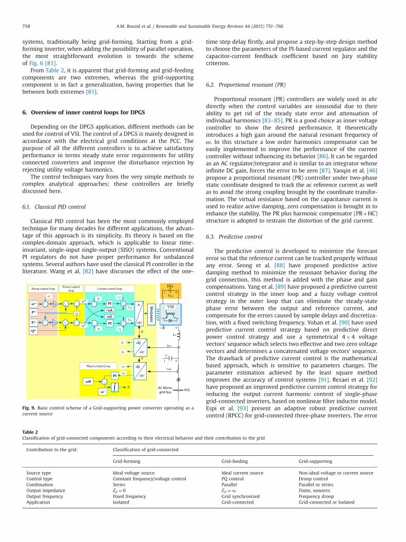
5.3.2. Grid supporting power converter operating as a current sourceThe power converter is based on the control scheme of a grid-
feeding inverter as shown in Fig. 9. The main objectives are tocontribute to regulate the voltage amplitude and frequency of boththe ac grid and the microgrid and supply the load connected to themicrogrid. The droop regulation techniques are implementedin grid-supporting power converters to regulate the exchange ofactive and reactive powers with the grid, in order to keep thegrid voltage frequency and amplitude under control. The mainidea to support the droop control comes from mimicking theself-regulation capability of the synchronous generator in grid-connection mode, decreasing the delivered active power [10]. Thescheme of Fig. 8 remains stable as long as the droop gains are nottoo large, while the same holds for the inverse droop gains ofFig. 7. It is noted that the scheme of Fig. 8 is far more popular inliterature than the one of Fig. 9. Two reasons could be thought offor explaining this: the first reason is the analogy with the controlof synchronous generators, the second reason being that droopcharacteristics for inverters were first implemented in UPS
Fig. 8. Basic control scheme of a Grid-supporting power converter operating as avoltage source
C
ABC
dq
ABC
dq
ABC
dq
PIP*
ffPI
PI
+ L
- L
Q*
Fig. 7. Basic control scheme of a grid-feeding voltage source inverter
A.M. Bouzid et al. / Renewable and Sustainable Energy Reviews 44 (2015) 751–766 757
systems, traditionally being grid-forming. Starting from a grid-forming inverter, when adding the possibility of parallel operation,the most straightforward evolution is towards the schemeof Fig. 6 [81].
From Table 2, it is apparent that grid-forming and grid-feedingcomponents are two extremes, whereas the grid-supportingcomponent is in fact a generalization, having properties that liebetween both extremes [81].
6. Overview of inner control loops for DPGS
Depending on the DPGS application, different methods can beused for control of VSI. The control of a DPGS is mainly designed inaccordance with the electrical grid conditions at the PCC. Thepurpose of all the different controllers is to achieve satisfactoryperformance in terms steady state error requirements for utilityconnected converters and improve the disturbance rejection byrejecting utility voltage harmonics.
The control techniques vary from the very simple methods tocomplex analytical approaches; these controllers are brieflydiscussed here.
6.1. Classical PID control
Classical PID control has been the most commonly employedtechnique for many decades for different applications, the advan-tage of this approach is its simplicity. Its theory is based on thecomplex-domain approach, which is applicable to linear time-invariant, single-input single-output (SISO) systems. ConventionalPI regulators do not have proper performance for unbalancedsystems. Several authors have used the classical PI controller in theliterature. Wang et al. [82] have discusses the effect of the one-
time step delay firstly, and propose a step-by-step design methodto choose the parameters of the PI-based current regulator and thecapacitor-current feedback coefficient based on Jury stabilitycriterion.
6.2. Proportional resonant (PR)
Proportional resonant (PR) controllers are widely used in abcdirectly when the control variables are sinusoidal due to theirability to get rid of the steady state error and attenuation ofindividual harmonics [83–85]. PR is a good choice as inner voltagecontroller to show the desired performance. It theoreticallyintroduces a high gain around the natural resonant frequency ofω. In this structure a low order harmonics compensator can beeasily implemented to improve the performance of the currentcontroller without influencing its behavior [86]. It can be regardedas an AC regulator/integrator and is similar to an integrator whoseinfinite DC gain, forces the error to be zero [87]. Yaoqin et al. [46]propose a proportional resonant (PR) controller under two-phasestatic coordinate designed to track the ac reference current as wellas to avoid the strong coupling brought by the coordinate transfor-mation. The virtual resistance based on the capacitance current isused to realize active damping, zero compensation is brought in toenhance the stability. The PR plus harmonic compensator (PRþHC)structure is adopted to restrain the distortion of the grid current.
6.3. Predictive control
The predictive control is developed to minimize the forecasterror so that the reference current can be tracked properly withoutany error. Seong et al. [88] have proposed predictive activedamping method to minimize the resonant behavior during thegrid connection, this method is added with the phase and gaincompensations. Yang et al. [89] have proposed a predictive currentcontrol strategy in the inner loop and a fuzzy voltage controlstrategy in the outer loop that can eliminate the steady-statephase error between the output and reference current, andcompensate for the errors caused by sample delays and discretiza-tion, with a fixed switching frequency. Yohan et al. [90] have usedpredictive current control strategy based on predictive directpower control strategy and use a symmetrical 4�4 voltagevectors’ sequence which selects two effective and two zero voltagevectors and determines a concatenated voltage vectors’ sequence.The drawback of predictive current control is the mathematicalbased approach, which is sensitive to parameters changes. Theparameter estimation achieved by the least square methodimproves the accuracy of control systems [91]. Rezaei et al. [92]have proposed an improved predictive current control strategy forreducing the output current harmonic content of single-phasegrid-connected inverters, based on nonlinear filter inductor model.Espi et al. [93] present an adaptive robust predictive currentcontrol (RPCC) for grid-connected three-phase inverters. The error
C
ABC
dq
ABC
dq
ABC
dq
PI*
ffPI
PI
+ L
- LE*
'
P*
Q*
Fig. 9. Basic control scheme of a Grid-supporting power converter operating as acurrent source
Table 2Classification of grid-connected components according to their electrical behavior and their contribution to the grid
Contribution to the grid. Classification of grid-connected
Grid-forming Grid-feeding Grid-supporting
Source type Ideal voltage source Ideal current source Non-ideal voltage or current sourceControl type Constant frequency/voltage control PQ control Droop controlCombination Series Parallel Parallel or seriesOutput impedance Zd ¼ 0 Zd ¼1 Finite, nonzeroOutput frequency Fixed frequency Grid synchronized Frequency droopApplication Isolated Grid-connected Grid-connected or Isolated
A.M. Bouzid et al. / Renewable and Sustainable Energy Reviews 44 (2015) 751–766758
correction is achieved by means of an adaptive strategy that worksin parallel with the deadbeat algorithm, therefore preserving thetypical fast response of the predictive law. Jiabing and Zhu [94]present a dead-beat predictive direct power control (DPC) strategyand its improved voltage-vector sequences for reversible three-phase grid-connected voltage-source converters (VSCs).
6.4. Dead-beat control
Dead-beat control (DB) is widely employed due to its highdynamic response in different applications; it is a very fastresponse method and it is suitable for the current controller.Timbus [95] and El-Saadany [96] have used this control forvoltage-source PWM converters in DPGS. Dead-beat controlbelongs to the predictive control family and it is developed tominimize the forecast error (predict the effect of the controlaction) so that the reference current can be tracked properlywithout any error. Henceforth utility current is predicted at thebeginning of each sample and the current error is found [97].Deadbeat control has a fast transient response and it is widelyemployed for active power filters too. Mattavelli et al. [98,99] haveused estimation of line voltage to improve the robustness of thecontroller to the parameters’ mismatch. Mohamed and El-Saadany[96] have proposed an improved dead beat controller using anadaptive self-tuning load model. Although, these methods boostthe robustness of dead beat controllers in case of parametersmismatch, the solutions applied make the structure of the con-troller more complex [95].
6.5. Hysteresis control
Hysteresis current control is a method for controlling a voltagesource inverter to force the grid injected current to follow areference current [100]. It is a controller with non-linear controllerloop with hysteresis comparators; an adaptive band of the con-troller has to be designed in order to obtain fixed switchingfrequency [20]. Moreover, several control strategies to provideflexible active and reactive power control during grid faults havebeen developed using the information of positive and negativesequence components. Malesani et al. [101] proposed differentmethods and algorithms to obtain fixed switching frequency.Depending on the method used, the complexity of the controllercan be increased considerably [102]. Among advantages using ahysteresis control is predominantly the simplicity, robustness,independence of load parameters and good transient response[103]. There are two main disadvantages by using the hysteresiscontroller [104]. It does not have any fixed switching frequencyand therefore a wide frequency spectrum and current ripple isrelatively high and can theoretically reach twice the size of theband limit for the phase current hysteresis controller. Xunjiangand Qin [105] have presented an adaptive hysteresis band controlalgorithm featuring dynamically modulated hysteresis band width.This algorithm shows that grid-connected inverters can injectsinusoidal current into the power grid, in phase with power gridvoltage, with the result of unity of power factor.
6.6. LQG/LQR
The idea about optimal methods is based on the criteriafunction (or performance index) describing the behavior of thesystem where the minimum (or maximum) of the criteria functionis obtained by the optimal control signal. When the system to becontrolled is linear, all states are measured and the criterion is aquadratic function of the states and control signal, the controlsystem will be a linear quadratic (LQ) control system [97]. Alepuzet al. [106–110] have presented a simple and easy to implement
approach for the control of the three level neutral-point-clamped(NPC) VSI converter based on the Linear Quadratic Regulator (LQR)and Gain-Scheduling control techniques. These control techniqueswork concurrently in the regulator; this allows the control of anystate variables including state variables related to DC-link voltages.The LQR is a proportional regulator; adding an integral actioncancels steady-state errors and the gain-scheduling control tech-nique allows for extending the application of the controller fromsmall-signal to large-signal operation. The advantages of thismethod are that information about the system is not lost and itallows obtaining better voltage regulation and load sharing simul-taneously. However, these state-feedback control schemes do notinherently include any means against external noise. For thispurpose Kalman filter (observer) can be used; it has the propertyto minimize the variance of the estimation error, when zero-meanGaussian random noise (i.e. white noise) is considered [111].The Kalman filter can be used to estimate the states of the system,when all states are not possible to measure and disturbancesconsiderably affect the system, and the control system would beknown as a linear quadratic Gaussian (LQG) control system [97].
6.7. Sliding mode controls
Sliding mode control (SMC) is recognized as robust controller(can provide good performance against parameter variations) witha high stability over a wide range of operating conditions [97]. It isa variable structure controller that contains a switching term,which can take the form of on-off control. However it suffers fromchattering problem. The key idea is to apply strong control actionwhen a system deviates from the desired behavior [112]. Theaddition of a well-designed feedforward controller to the SMCimproves the zero tracking speed as well as a non-overshoottransient performance. Sometimes, it is difficult to design a SMC toexhibit both suitable transient and zero steady state performance.In this case, a feedforward controller can be employed [113,114].Xiang et al. [112] have proposed a fixed switching frequencyintegral resonant SMC (IRSMC) based on pulse width modulation(PWM) under d-q rotation frame for three-phase grid-connectedinverter with LCLfilter. The chattering problem of SMC is elimi-nated by adopting GAO's reaching law. In order to obtain anoptimal trade-off between the elimination of chattering and theguarantee of performance of SMC, the parameters of SMC areoptimized according to the ripple of the system output based onPWM. Moreover, an extra integral term of grid current error isintroduced in the sliding surface to eliminate the fundamentalcomponent of the tracking error. In order to suppress the gridcurrent THD effectively, multiple resonant terms of the gridcurrent error are added to the sliding function. Shang and Sun[115] present an improved means of direct power control (DPC) ofgrid-connected voltage-sourced inverters (GC-VSIs) when thenetwork voltage is unbalanced. A new power compensation methodis proposed for the SMC-based DPC during network unbalance toachieve three selective control targets, that is, obtaining sinusoidaland symmetrical grid current, removing reactive power ripples andcancelling active power ripples. Jiabing and Bin [116] proposed aDPC strategy employing a nonlinear sliding mode control scheme todirectly calculate the required converter voltage so as to eliminatethe active and reactive power errors without involving any synchro-nous coordinate transformations. Besides, no extra current controlloops are required, thereby simplifying the system design andenhancing the transient performance.
6.8. H1 controllers
The H1 methods are used to synthesize controllers thatstabilize the process not only for its nominal parameters values,
A.M. Bouzid et al. / Renewable and Sustainable Energy Reviews 44 (2015) 751–766 759
but for the case in which the system parameters vary withincertain limits; they can also guarantee the performance with theworst-case disturbance. Its basic principle is to minimize theinfluence of the disturbances to outputs. Hornik and Zhong [117]have proposed a current controller design based on H1 andrepetitive control techniques for grid-connected inverters toreduce current total harmonic distortion (THD). The H1 currentcontroller allows maintaining a balanced neutral point for a three-phase four-wire inverter and can eliminate the current flowingthrough the split capacitors [118]. The current controller consistsof an internal model and a stabilizing compensator, using the H1control theory, to deal a very large number of harmonics simulta-neously by injecting a clean sinusoidal current to the grid, even inthe presence of nonlinear/unbalanced loads and/or grid-voltagedistortions [119]. A voltage controller based on H1 and repetitivecontrol techniques is proposed, and a frequency adaptive mechan-ism is introduced to improve system performance and to copewith grid frequency variations. The repetitive control, based on theinternal model principle, offers excellent performance for voltagetracking, as it can deal with a very large number of harmonicssimultaneously [120]. The cascaded current-voltage control strat-egy proposed includes an inner voltage loop and an outer currentloop, with both controllers designed using the H1 repetitivecontrol strategy, in order to simultaneously improve the powerquality of the inverter local load voltage and the current flowingwithin the micro grid. This leads to a very low THD in both themicro grid voltage and the grid current. It also enables seamlesstransfer of the operation mode from stand-alone to grid-connected or vice versa and also allows grid-connected invertersto inject balanced clean currents to the grid even when the localloads (if any) are unbalanced and/or nonlinear [121] [122].
6.9. Repetitive controller (RC)
Repetitive feedback control (RC) has been derived from the conceptof iterative learning control (ILC) and it can be used for control ofutility converters with periodic reference signals or disturbances.The RC theory, regarded as a simple learning control method, providesan alternative to eliminating periodic errors in dynamic systems, usingthe internal model principle [123]. In these controllers, error betweenthe reference value and feedback utility connected current is used togenerate a new reference for the next fundamental cycle [124] [125].RC is mathematically equivalent to a parallel combination of anintegral controller, many resonant controllers and a proportionalcontroller [126] and accordingly good disturbance rejection can beachieved at these frequencies. To ensure stability, a low-pass filterneeds to be incorporated within the repetitive controller to attenuatethe high frequency resonant peaks of the controller gain (above thesystem's cross-over frequency), without significantly affecting the lowfrequency resonant peaks corresponding to significant grid harmonicsthat need to be rejected [124]. Liu et al. [125] proposed a controlstrategy to damp the harmonics: the inverter output current isregulated by PI controller and grid current is controlled by repetitivecontroller (RC) for three-phase grid-connected voltage source inverter(VSI) with LCL filter under d-q rotating frame. Chen et al. [127]proposed an improved control scheme based on the T0/6 repetitivecontrol for three-phase grid-connected inverters. The proposedscheme adopts T0/6 as the delay time in the positive-rotating andnegative-rotating synchronous reference frames to suppress the6n71 harmonics. A new auxiliary function based on the linearinterpolation is proposed to maintain the ideal repetitive controlperformance when one-sixth of the ratio of the sampling frequencyto the grid fundamental frequency is non-integer. Asbafkan et al. [128]have presented a frequency adaptive repetitive controller (RC), whichis based on the internal model principle (IMP). This controller isequivalent to a PR controller and infinite number of ideal resonant
filters (harmonic compensators) with infinite gains. It is simple for theimplementation and the ability to tune all the resonant frequenciessimultaneously through the adaptation of the RC time delay para-meter. But it can degrade significantly in the case of grid frequencyvariations while in the frequency adaptive scheme the high perfor-mance of the current controller is still preserved. Hornik and Zhong[117–122] proposed a voltage controller for grid-connected invertersbased on H1 and repetitive control techniques based on the internalmodel principle, which leads to a very low THD and improves trackingperformance. Jiang and Peng [129] use a high performance repetitivecurrent controller for grid connected inverters based on a high-resonance-frequency LCL filter (deliberately selected higher than 40%of the inverter switching frequency). By properly selecting the currentsensor position and introducing an extra delay with a low pass filteron the feedback path, the system stability is obtained without theadoption of any extra damping techniques. High power factor (40.99)and very low THD (1.72%�3.72%) are guaranteed under both heavyand light load conditions. Loh et al. [130] have proposed a novelrepetitive controller which can realize multi-harmonics rejection witha simple structure. The novel controller has been only verified in anL-filtered inverter. Guofei et al. [131] use dual close-loop control withfeed forward for limiting the resonance peak of the LCL filter and forbringing high gain and rapid response; repetitive control can providethe system with the ability to attenuate grid harmonics and goodrobustness. Dong et al. [132] proposed an improved repetitive controlscheme with a specially designed finite impulse response (FIR) filter.The FIR filter cascaded with a traditional delay function can approx-imate the ideal repetitive control function of any ratio. The proposedscheme varies the FIR filter according to varied grid frequency andmaintains its resonant frequencies matching the grid fundamental andharmonics.
6.10. Neural networks and fuzzy control methods
Neural networks (NN) control methods have been mostly usedin current controllers because of their high robustness. Mohamedand El-Saadany [133] present an adaptive discrete-time grid-voltage sensorless interfacing scheme for grid-connected distrib-uted generation inverters, based on neural network identification.A reliable solution to the present nonlinear estimation problem ispresented by combining a neural network interfacing-parametersidentifier (NNIPI) with a neural network grid-voltage estimator(NNGVE). The self-learning feature of the NN adaptation algorithmallows feasible and easy adaptation design at different griddisturbances and operating conditions. This provides improvedrobust control performance as compared to existing controllers,and integrates new control functions such as line-voltage sensorlesscurrent control and synchronization. The overall control system hasa modest complexity and computational demand, which enabledreal-time implementation using commercial grade digital signalprocessors [134].
Chao and Dagui [135] studied to optimize the design of currentcontrollers: PI controller, fuzzy logic controller (FLC) and PI-FLCdouble-mode controller to reduce overshoots and improve thetracking error performance.
7. Review of software tools
Several software tools have been deployed for the sizing, simula-tion, testing and optimization of hybrid systems. We present differentsoftwares and hardwares used for study and integrate hybrid systemsand microgrids.
A.M. Bouzid et al. / Renewable and Sustainable Energy Reviews 44 (2015) 751–766760
7.1. Optimization software tools
One of the most used software tools with this purpose isHOMER (Hybrid Optimization Model for Electric Renewables),originally developed at the National Renewable Energy Laboratory,USA, and enhanced and distributed by HOMER Energy [136].HOMER includes tools for optimization of hybrid systems, in orderto determine the optimal architecture and control strategy [137].The sensitivity analysis is also performed to obtain the optimalconfiguration of hybrid renewable energy based on differentcombinations of generating systems [138]. It can optimize hybridsystems consisting of photovoltaic generators, biomass, batteries,wind turbines, hydraulic turbines, AC generators, fuel cells, elec-trolyzers, hydrogen tanks, inverters (DC/AC converters), rectifiers(AC/DC converters), and combined heat and power (CHP). Theloads can be AC, DC, and/or hydrogen-based loads, as well asthermal loads [139].
HYBRID2 [140] is a user friendly tool to perform detailed longterm performance and economic analysis of hybrid power sys-tems; it was developed by the Renewable Energy ResearchLaboratory (RERL) of the University of Massachusetts. HYBRID2was designed to study a wide variety of hybrid power systems, e.g.multiple different types wind turbines, photovoltaic generators,multiple diesel generators, battery storage, four types of powerconversion devices, and three types of electrical loads. Systems canbe modeled in AC, DC or using both AC and DC. A variety ofdifferent control strategies and components such as fuel cells orelectrolyzers can be implemented in the software. The simulationis very precise, as it can define time intervals from ten minutes toone hour [139]. The most used software is Matlabs/SimulinkTM
developed by The Mathworks inc. [141].HOGA [142] (Hybrid Optimization by Genetic Algorithms)
was developed by the Electric Engineering Department of theUniversity of Zaragoza (Spain) for the simulation and optimizationof Hybrid Renewable Systems for generation of electrical energy(DC and/or AC) and/or hydrogen. Based on traditional geneticalgorithms, HOGA has been improved with a robust selectionoperator and an intelligent crossover operator [143], which can bemono-objective (financial optimization) or multi-objective (mini-mization of CO2 emissions or of unmet load, in case of energy notserved). It allows optimizing hybrid generation systems integrat-ing renewable energies (such as photovoltaic panels and windturbines), hydraulic turbines, AC generators, and storage systemsbased on batteries or hydrogen (fuel cells, electrolyzers, andhydrogen storage tanks), rectifiers, and inverters. The loads canbe AC, DC, and/or hydrogen-loads or water pumping loads [144].
HYDROGEMS [145–147] is not a program, but a series oflibraries developed at the Institute for Energy Technology (IFE,Norway). The libraries are used by TRNSYS and by EngineeringEquation Solver (EES) softwares. HYDROGEMS-models can be usedto analyze the performance of hydrogen energy systems down toone-minute time-steps. The libraries developed by HYDROGEMSmodel include the following components: wind energy conversionsystems, photovoltaic systems, water electrolysis, fuel cells, hydrogengas storage, metal hydride hydrogen storage, hydrogen compressor,secondary batteries (lead-acid), power conditioning equipment, anddiesel engine generators, e.g. multi-fuels, including hydrogen andDC/AC converters.
RAPSim [148] (Renewable Alternativ Powersystems Simulation)is a software able to simulate grid-connected or standalonemicrogrids with solar, wind, or other renewable energy sources.This software is helpful for optimal placement of distributedgeneration units in a microgrid.
SOMES [149] (Simulation and Optimization Model for renew-able Energy Systems) has been developed at Utrecht University(The Netherlands). It can simulate the performances of renewable
energy systems that may contain renewable energy sources, suchas PV arrays and wind turbines, a motor generator, a grid, batterystorage, and several types of converters.
TRNSYS [150] (Transient Energy System Simulation Program) isan energy system simulation software initially developed tosimulate thermal systems. Developed in Fortran, it is commerciallyavailable since 1975 by the University of Wisconsin and theUniversity of Colorado (USA) continues development with inter-national collaboration of the United States, France, and Germany.It is a hybrid system simulator, including photovoltaic panels, windturbines, thermal solar systems, low energy buildings and HVACsystems, renewable energy systems, cogeneration, fuel cells, andother systems. The simulation is carried out with great precision,showing graphics with great detail and precision. TRNSYS hasbecome a reference software for researchers and engineers aroundthe world, but it does not carry out optimization.
7.2. Simulation and real-time implementation platforms
SPS/Simulink [151,152] is a widespread graphical interface,modeling and simulation tool, used in many engineering fields.SimPowerSystems (SPS) developed by Hydro-Quebec Research Cen-ter (IREQ) is a Simulink blockset that provides multiple modelcomponents, all based on electromechanical and electromagneticequations, for the simulation of power systems and machine drives.The user can interface his own models in SPS/Simulink and SPS canbe used in conjuncture with the various toolboxes in Simulink.
The RTDS [153]. Simulator is designed specifically to simulateelectrical power systems and to test physical equipment such ascontrol and protection devices. The base components available inRTDS for study of microgrids are: real time network solution,sources, transformers, and distributed generators, such as windturbines, photovoltaics, fuel cells and various other power sourcescan be represented by library components, while the correspond-ing VSC converters can be freely configured in small time step subnetworks.
PSCAD™/EMTDC™ [154] is a software allowing building, simu-lation, and modeling for renewable energy integration and powersystem. It offers an array of solutions in the following areas:system integration/impact studies (wind and solar), wind systemcustom equipment model development, FACTs and synchronouscondenser (synchronous capacitor or synchronous compensator)based solutions for performance improvement. It also includes acomprehensive library of system models.
OPAL-RT [155] is a leader in the development of PC/FPGA BasedReal-Time Digital Simulators, Hardware-In-the-Loop (HIL) testingequipment and Rapid Control Prototyping (RCP) systems. RT-LABsoftware from OPAL-RT is fully integrated with MATLAB/Simu-links and various hardware and software platforms are availablefor power systems and power apparatus. These systems are usedto design, test and optimize control and protection for differentsystems, such as power grids, microgrids, power electronics, andso forth. Among other systems, communication layer of commu-nication grids can also be studied.
Different researchers have used these tools in their researchworks on microgrids, for instance:
Ibarra Hernandez et al. [156] propose the energy managementand control for islanded microgrids using multi-agents formed byphotovoltaic (PV) solar energy, batteries and resistive and rotatingmachines loads. The management and control of the PV system isperformed in JADE (Java Agent DEvelopment Framework), whilethe microgrid model is simulated in RSCAD/RTDS (Real-TimeDigital Simulator).
Yangkai et al. [157] propose a hardware in the loop simulation(HILS) system based on NI-PXI to test the microgrid operation and
A.M. Bouzid et al. / Renewable and Sustainable Energy Reviews 44 (2015) 751–766 761
control. This microgrid includes a doubly-fed induction generator(DFIG), a battery energy storage system (BESS) and a desalination load.
Etemadi et al. [158] present the fundamental concepts of ageneralized central power management system and a decentra-lized robust control strategy for autonomous mode of operation ofa microgrid that includes multiple distributed energy resource(DER) units. The digital time-domain simulation is studied inPSCAD/EMTDC platform and the performance of the controlsystem is also verified based on hardware-in-the-loop (HIL)studies in the RTDS environment.
Farzinfar et al. [159] present the real-time simulation of MGs,whose model is first constructed in the MATLABs/SimulinkTM andits implementation using discrete real-time simulator eMEGAsimdeveloped by Opal-RT Technology Inc. Parallel processing is usedfor simulation in RT-LAB.
Lin-Yu [160] present a consensus-based droop control methoddeveloped for autonomous power management and load sharing.Dynamical simulations of a 6-DIC/14-bus microgrid are performedon a real-time simulator developed by OPAL-RT with detaileddynamical converter models.
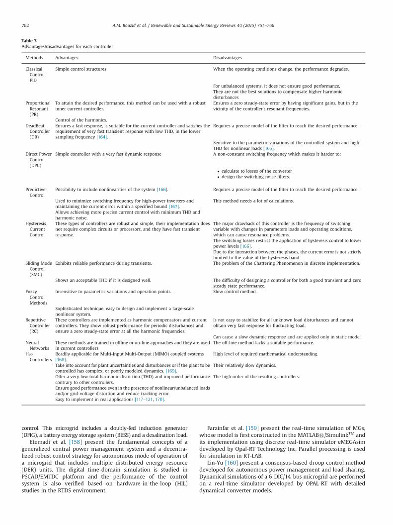
Table 3Advantages/disadvantages for each controller
Methods Advantages Disadvantages
ClassicalControlPID
Simple control structures When the operating conditions change, the performance degrades.
For unbalanced systems, it does not ensure good performance.They are not the best solutions to compensate higher harmonicdisturbances
ProportionalResonant(PR)
To attain the desired performance, this method can be used with a robustinner current controller.
Ensures a zero steady-state error by having significant gains, but in thevicinity of the controller’s resonant frequencies.
Control of the harmonics.DeadBeatController(DB)
Ensures a fast response, is suitable for the current controller and satisfies therequirement of very fast transient response with low THD, in the lowersampling frequency [164].
Requires a precise model of the filter to reach the desired performance.
Sensitive to the parametric variations of the controlled system and highTHD for nonlinear loads [165].
Direct PowerControl(DPC)
Simple controller with a very fast dynamic response A non-constant switching frequency which makes it harder to:
• calculate to losses of the converter• design the switching noise filters.
PredictiveControl
Possibility to include nonlinearities of the system [166]. Requires a precise model of the filter to reach the desired performance.
Used to minimize switching frequency for high-power inverters andmaintaining the current error within a specified bound [167].
This method needs a lot of calculations.
Allows achieving more precise current control with minimum THD andharmonic noise.
HysteresisCurrentControl
These types of controllers are robust and simple, their implementation doesnot require complex circuits or processors, and they have fast transientresponse.
The major drawback of this controller is the frequency of switchingvariable with changes in parameters loads and operating conditions,which can cause resonance problems.The switching losses restrict the application of hysteresis control to lowerpower levels [166].Due to the interaction between the phases, the current error is not strictlylimited to the value of the hysteresis band
Sliding ModeControl(SMC)
Exhibits reliable performance during transients. The problem of the Chattering Phenomenon in discrete implementation.
Shows an acceptable THD if it is designed well. The difficulty of designing a controller for both a good transient and zerosteady state performance.
FuzzyControlMethods
Insensitive to parametric variations and operation points. Slow control method.
Sophisticated technique, easy to design and implement a large-scalenonlinear system.
RepetitiveController(RC)
These controllers are implemented as harmonic compensators and currentcontrollers. They show robust performance for periodic disturbances andensure a zero steady-state error at all the harmonic frequencies.
Is not easy to stabilize for all unknown load disturbances and cannotobtain very fast response for fluctuating load.
Can cause a slow dynamic response and are applied only in static mode.NeuralNetworks
These methods are trained in offline or on-line approaches and they are usedin current controllers
The off-line method lacks a suitable performance.
H∞Controllers
Readily applicable for Multi-Input Multi-Output (MIMO) coupled systems[168].
High level of required mathematical understanding.
Take into account for plant uncertainties and disturbances or if the plant to becontrolled has complex, or poorly modeled dynamics. [169].
Their relatively slow dynamics.
Offer a very low total harmonic distortion (THD) and improved performancecontrary to other controllers.
The high order of the resulting controllers.
Ensure good performance even in the presence of nonlinear/unbalanced loadsand/or grid-voltage distortion and reduce tracking error.Easy to implement in real applications [117–121, 170].
A.M. Bouzid et al. / Renewable and Sustainable Energy Reviews 44 (2015) 751–766762
8. Discussion and conclusion
This article summarizes the recent developments for intercon-necting distributed power generators with electric power systems.DPGSs are discussed in this article. The hierarchical control ofintelligent microgrids was described showing the different oper-ating modes (primary, secondary and tertiary) as a control hier-archical strategy. The contribution of the power inverter to theformation of the grid voltage and frequency is also studied.A review of literature published on the various control strategiesof DPGS was presented and a comparison is presented in Table 3.This comparative study lists the advantages and disadvantages foreach controller in term of robustness against parameters variation,rapidity, stability, performance, harmonic elimination and thenonlinearities of the system. We note that with the advancementof power electronics, the researchers developed various controlstrategies for harmonics attenuation, for securing the stability andfor power quality. These controllers are categorized as classical andadvanced methods and each method is used depending on therequired performance. The future trends in microgrid technologiesare toward the use of advanced decentralized control techniques,such as multi-agent systems where the general purpose of con-sensus algorithms is to allow a set of agents to reach an agreementon a quantity of interest by exchanging information throughcommunication network [161–163]. Furthermore, in the macro-scopic level, multiple microgrids forming interconnected micro-grids clusters and DC microgrids and low voltage DC distributionsystems are becoming very important, because they present someadvantages such as the reduction of conversion losses of invertersbetween DC output sources and loads, which increases enhancingthe system efficiency. Synchronization is not needed and is not anissue for connection of DGs and ESSs to the bus and the main gridin DC MGs. Moreover there is no need for control of frequencyand phase.
References
[1] Chicco G, Mancarella P. Distributed multi-generation: a comprehensive view.Renew Sustain Energy Rev 2009;13:535–51.
[2] Llaria A, Curea O, Jiménez J, Camblong H. Survey on microgrids: unplannedislanding and related inverter control techniques. Renew Energy 2011;36:2052–61.
[3] Xiaonan L, Guerrero JM, Kai S, Vasquez JC, Teodorescu R, Lipei H. Hierarchicalcontrol of parallel AC-DC converter interfaces for hybrid microgrids. IEEETrans Smart Grid 2014;5:683–92.
[4] Vasquez JC, Guerrero JM, Miret J, Castilla M, de V, x00F, et al. Hierarchicalcontrol of intelligent microgrids. Ind Electron Magazine IEEE 2010;4:23–9.
[5] Guerrero JM, Vasquez JC, Matas J, Luis GV, Castilla M. Hierarchical control ofdroop-controlled AC and DC microgrids- A general approach toward stan-dardization. IEEE Trans Ind Electron 2011;58:158–72.
[6] O. Palizban, K. Kauhaniemi, J.M. Guerrero, Microgrids in active networkmanagement—Part I: Hierarchical control, energy storage, virtual powerplants, and market participation, Renew Sustain Energy Rev, http://dx.doi.org/10.1016/j.rser.2014.01.016, in press..
[7] Sirviö KH. Integrating low voltage distribution systems to distributionautomation. Finland: Master, Faculty of technology, University Of Vaasa;2012.
[8] J.M. Guerrero, J.C. Vasquez, R. Teodorescu, Hierarchical control of droop-controlled DC and AC microgrids- a general approach towards standardiza-tion, in Thirty-fifth annual conference of IEEE, industrial electronics, IECON‘09. 2009, pp. 4305–10.
[9] J.M. Guerrero, J.C. Vasquez, J. Matas, J.L. Sosa, and L.G. de Vicuna, Paralleloperation of uninterruptible power supply systems in microgrids, inEuropean conference on, power electronics and applications, 2007, pp. 1–9.
[10] Rocabert J, Luna A, Blaabjerg F, Rodri x, guez P. Control of power convertersin AC microgrids. IEEE Trans Power Electron 2012;27:4734–49.
[11] Guerrero JM, Chandorkar M, Lee T, Loh PC. Advanced control architecturesfor intelligent microgrids-Part I: decentralized and hierarchical control. IEEETrans Ind Electron 2013;60:1254–62.
[12] Vasquez JC, Guerrero JM, Savaghebi M, Eloy-Garcia J, Teodorescu R. Model-ing, analysis, and design of stationary-reference-frame droop-controlledparallel three-phase voltage source inverters. IEEE Trans Ind Electron2013;60:1271–80.
[13] Bhattacharyya SC. Review of alternative methodologies for analysing off-gridelectricity supply. Renew Sustain Energy Rev 1// 2012;16:677–94.
[14] J.M. Guerrero, J.C. Vasquez, R. Teodorescu, Hierarchical control of droop-controlled DC and AC microgrids - a general approach towards standardiza-tion, in Thirty-fifth annual conference of IEEE, industrial electronics, IECON‘09. 2009, pp. 4305–4310.
[15] J.M. Guerrero, N. Berbel, J. Matas, L.G. de Vicuna, J. Miret, Decentralizedcontrol for parallel operation of distributed generation inverters in micro-grids using resistive output impedance, in Thirty-second annual conferenceon, IEEE industrial electronics, IECON, 2006, pp. 5149–5154.
[16] Villenueve PL. Concerns generated by islanding [electric power generation].IEEE Power Energy Magazine 2004;2:49–53.
[17] Chandorkar MC, Divan DM, Adapa R. Control of parallel connected invertersin standalone AC supply systems. IEEE Trans Ind Appl 1993;29:136–43.
[18] H. Chaoyong, H. Xuehao, H. Dong, Hierarchical control techniques applied inmicro-grid, in Power system technology (POWERCON), 2010 internationalconference on, 2010, pp. 1-5.
[19] Guerrero JM, Vasquez JC, Matas J, Castilla M, de Vicuna LG. Control strategyfor flexible microgrid based on parallel line-interactive UPS systems. IEEETrans Ind Electron 2009;56:726–36.
[20] Blaabjerg F, Teodorescu R, Liserre M, Timbus AV. Overview of control andgrid synchronization for distributed power generation systems. IEEE TransInd Electron 2006;53:1398–409.
[21] Justo JJ, Mwasilu F, Lee J, Jung J-W. AC-microgrids versus DC-microgrids withdistributed energy resources: a review. Renew Sustain Energy Rev2013;24:387–405.
[22] Rodriguez P, Timbus AV, Teodorescu R, Liserre M, Blaabjerg F. Flexible activepower control of distributed power generation systems during grid faults.IEEE Trans Indust Electron 2007;54:2583–92.
[23] F. Blaabjerg, F. Iov, Z. Chen, K. Ma, Power electronics and controls for windturbine systems, in IEEE international, energy conference and exhibition(EnergyCon), 2010, pp. 333–344.
[24] Lidula N, Rajapakse A. Microgrids research: a review of experimentalmicrogrids and test systems. Renew Sustain Energy Rev 2011;15:186–202.
[25] M. Barnes, Real-world microgrid-an overview, in IEEE international con-ference on system of systems engineering, San Antonio, USA, 2007, 2007.
[26] F.Z. Peng, Y.W. Li, L.M. Tolbert, Control and protection of power electronicsinterfaced distributed generation systems in a customer-driven microgrid, inPES'09. IEEE Power & energy society general meeting, 2009, pp. 1–8.
[27] Borbely A-M, Kreider JF. Distributed generation: the power paradigm for thenew millennium. CRC press; 2001.
[28] R. Lasseter, A. Akhil, C. Marnay, J. Stephens, J. Dagle, R. Guttromson, et al., TheCERTS microgrid concept, white paper on integration of distributed energyresources, California energy commission, office of power technologies-USdepartment of energy, LBNL-50829, ⟨http://certs.lbl.gov⟩, 2002.
[29] Zamora R, Srivastava AK. Controls for microgrids with storage: review,challenges, and research needs. Renew Sustain Energy Rev 2010;14:2009–18.
[30] R. Lasseter, A. Akhil, C. Marnay, J. Stephens, J. Dagle, R. Guttromson, et al., TheCERTS microgrid concept, White paper for transmission reliability program,Office of Power Technologies, US Department of Energy, 2002.
[31] Lasseter RH. Smart distribution: coupled microgrids. Proc IEEE 2011;99:1074–82.
[32] Hatziargyriou N, Jenkins N, Strbac G, Lopes JP, Ruela J, Engler A, et al.Microgrids–large scale integration of microgeneration to low voltage grids.CIGRE 2006:C6–309.
[33] Tao L, Schwaegerl C. Advanced architectures and control concepts for moremicrogrids, EC Project, Tech. Rep. SES6-0198642009.
[34] Sarkar, Joydeep, and Pramod Yade. "Structuring DC Micro-Grid for IntegratingRenewable Energy in a DC Load Dominant Electrical Environment."INTERNA-TIONAL JOURNAL OF ENGINEERING SCIENCES & RESEARCH TECHNOLOGY, 2014http://www.ijesrt.com/issues%20pdf%20file/Archives-2014/July-2014/89.pdf.
[35] Lasseter RH, Piagi P. Control and design of microgrid components. Universityof Wisconsin-Madison, PSERC Publication; 2006 (06-03 Jan)⟨https://scholar.google.ca/scholar?hl¼en&q¼Controlþandþdesignþofþmicrogridþcom-ponents&btnG¼&as_sdt¼1%2C5&as_sdtp¼ ⟩.
[36] Li YW, Kao C-N. An accurate power control strategy for power-electronics-interfaced distributed generation units operating in a low-voltage multibusmicrogrid. IEEE Trans Power Electron 2009;24:2977–88.
[37] Laaksonen H, Kauhaniemi K. Synchronized re-connection of island operatedLV microgrid back to utility grid. Innovative smart grid technologiesconference Europe (ISGT Europe) 2010:1–8 (2010 IEEE PES).
[38] Jiayi H, Chuanwen J, Rong X. A review on distributed energy resources andMicroGrid. Renew Sustain Energy Rev 2008;12:2472–83.
[39] Lasseter RH. Microgrids and distributed generation. J Energy Eng2007;133:144–9.
[40] Lasseter RH. Microgrids and distributed generation. Intelligent AutomationSoft Computing 2010;16:225–34.
[41] Lasseter RH, Paigi P. Microgrid: a conceptual solution. Power ElectronicsSpecialists Conference 2004:4285–90 (2004. PESC 04. 2004 IEEE 35thAnnual).
[42] Laaksonen H, Kauhaniemi K. Stability of microgrid with different configura-tions after islanding due to fault in the utility grid. Int Rev Electrical Eng2008;3.
[43] Mahmoud MS, Azher Hussain S, Abido MA. Modeling and control ofmicrogrid: an overview. J Franklin Inst 5// 2014;351:2822–59.
A.M. Bouzid et al. / Renewable and Sustainable Energy Reviews 44 (2015) 751–766 763
[44] Pepermans G, Driesen J, Haeseldonckx D, Belmans R, D'haeseleer W.Distributed generation: definition, benefits and issues. Energy Policy 4//2005;33:787–98.
[45] Zhixiang Z, Zheng W, Ming C. Modeling, analysis, and design of multi-function grid-interfaced inverters with output LCL filter. IEEE Trans PowerElectron 2014;29:3830–9.
[46] Yaoqin J, Jiqian Z, Xiaowei F. Direct grid current control of LCL-filtered grid-connected inverter mitigating grid voltage disturbance. IEEE Trans PowerElectron 2014;29:1532–41.
[47] Jinming X, Shaojun X, Ting T. Active damping-based control for grid-connected LCL filtered inverter with injected grid current feedback only.IEEE Trans Indust Electron 2014;61:4746–58.
[48] Hamzeh M, Karimi Y, Asadi E, Oraee H. Design and implementation of asingle phase grid-connected PV inverter with a new active damping strategy,in. Power Electronics Drive Systems and Technologies Conference (PEDSTC)2014:72–7 (2014 5th).
[49] Chenlei B, Xinbo R, Xuehua W, Weiwei L, Donghua P, Kailei W. Step-by-stepcontroller design for LCL-type grid-connected inverter with capacitorcurrent-feedback active-damping. IEEE Trans Power Electron 2014;29:1239–53.
[50] Weimin W, Yuanbin H, Tianhao T, Blaabjerg F. A new design method for thepassive damped LCL and LLCL filter-based single-phase grid-tied inverter.IEEE Trans Indust Electron 2013;60:4339–50.
[51] Agorreta JL, Borrega M. Lo, x, J. pez, L. Marroyo, Modeling and control of Nparalleled grid-connected inverters With LCL filter coupled due to gridimpedance in PV plants. IEEE Trans Power Electron 2011;26:770–85.
[52] Georgakis D, Papathanassiou S, Hatziargyriou N, Engler A, Hardt C. Operationof a prototype microgrid system based on micro-sources quipped with fast-acting power electronics interfaces. Power electronics specialists conference2004;4:2521–6 (2004. PESC 04. 2004 IEEE 35th Annual).
[53] Dimeas AL, Hatziargyriou ND. Operation of a multiagent system for micro-grid control. IEEE Trans Power Syst 2005;20:1447–55.
[54] Vandoorn TL, Vasquez JC, De Kooning J, Guerrero JM, Vandevelde L.Microgrids: hierarchical control and an overview of the control and reservemanagement strategies. IEEE Indust Electron Mag 2013;7:42–55.
[55] Chamorro HR, Diaz NL. Hierarchical power flow control in low voltagemicrogrids. North american power symposium (NAPS) 2013;2013:1–5.
[56] Micallef A, Apap M, Spiteri-Staines C, Guerrero JM, Vasquez JC. Reactivepower sharing and voltage harmonic distortion compensation of droopcontrolled single phase islanded microgrids. IEEE Trans Smart Grid2014;5:1149–58.
[57] Savaghebi M, Guerrero JM, Jalilian A, Vasquez JC, Tzung-Lin L. Hierarchicalcontrol scheme for voltage Harmonics Compensation in an islanded droop-controlled microgrid, in Power electronics and drive systems (PEDS), 2011IEEE Ninth International Conference on, 2011, pp. 89–94.
[58] Savaghebi M, Guerrero JM, Jalilian A, Vasquez JC. Hierarchical control schemefor voltage unbalance compensation in islanded microgrids,” in IECON 2011– Thirty-seveth annual conference on IEEE industrial electronics society,2011, pp. 3158–63.
[59] Palizban O, Kauhaniemi K, Guerrero JM. Microgrids in active networkmanagement—Part I: hierarchical control, energy storage, virtual powerplants, and market participation. Renew Sustain Energy Rev 8//2014;36:428–39.
[60] Vasquez JC, Mastromauro RA, Guerrero JM, Liserre M. Voltage supportprovided by a droop-controlled multifunctional inverter. IEEE Trans IndustElectron 2009;56:4510–9.
[61] Bidram A, Davoudi A. Hierarchical structure of microgrids control system.IEEE Transactions on Smart Grid 2012;3:1963–76.
[62] Peas Lopes JA, Moreira CL, Madureira AG. Defining control strategies foranalysing microgrids islanded operation, in, IEEE Russia Power Tech; 2005,1–7.
[63] Guerrero JM, Berbel N, Matas J, Sosa JL, Cruz J, Alentorn A. Decentralizedcontrol for parallel operation of distributed generation inverters usingresistive output impedance, in, European conference on power electronicsand applications; 2005, pp. 10 pp.-P.10.
[64] Coelho EAA, Cortizo PC, Garcia PFD. Small-signal stability for parallel-connected inverters in stand-alone AC supply systems. IEEE Trans IndustAppl 2002;38:533–42.
[65] Tsai-Fu W, Yu-Kai C, Yong-Heh H. 3C strategy for inverters in paralleloperation achieving an equal current distribution. IEEE Trans Indust Electron2000;47:273–81.
[66] Hongying W, Dong L, Dehua Z, Kaiwei Y, Jinfa Z. A current-mode controltechnique with instantaneous inductor-current feedback for UPS inverters,in Applied power electronics conference and exposition, 1999. APEC ‘99.Fourteenth Annual; 1999, pp. 951-957 2.
[67] Shafiee Q, Guerrero JM, Vasquez JC. Distributed Secondary Control forIslanded Microgrids—A Novel Approach. IEEE Trans Power Electron2014;29:1018–31.
[68] Savaghebi M, Vasquez JC, Jalilian A, Guerrero JM. Secondary control forcompensation of voltage harmonics and unbalance in microgrids, in , ThirdIEEE international symposium on power electronics for distributed genera-tion systems (PEDG); 2012, pp. 46–53.
[69] Savaghebi M, Jalilian A, Vasquez JC, Guerrero JM. Secondary control forvoltage quality enhancement in microgrids. IEEE Trans Smart Grid2012;3:1893–902.
[70] Savaghebi M, Jalilian A, Vasquez JC, Guerrero JM. Secondary control schemefor voltage unbalance compensation in an islanded droop-controlled micro-grid. IEEE Trans Smart Grid 2012;3:797–807.
[71] Xiongfei W, Guerrero JM, Blaabjerg F, Zhe C. Secondary voltage control forharmonics suppression in islanded microgrids,” in IEEE power and energysociety general meeting, 2011, pp. 1–8.
[72] Savaghebi M, Guerrero JM, Jalilian A, Vasquez JC. Secondary control forvoltage unbalance compensation in an islanded microgrid, in IEEE interna-tional conference smart grid communications (SmartGridComm), 2011,pp. 499–504.
[73] Jung-Wook P, Harley RG. Secondary control for a series reactive compensatorbased on a voltage-source PWM inverter. IEEE Power Electron Lett2004;2:117–20.
[74] Shafiee Q, Stefanovic C, Dragicevic T, Popovski P, Vasquez JC, Guerrero JM.Robust networked control scheme for distributed secondary control ofislanded microgrids. IEEE Trans Indust Electron 2014;61:5363–74.
[75] Bidram A, Davoudi A, Lewis FL, Guerrero JM. Distributed cooperativesecondary control of microgrids using feedback linearization. IEEE TransPower Syst 2013;28:3462–70.
[76] Shafiee Q, Vasquez JC, Guerrero JM. Distributed secondary control forislanded MicroGrids – A networked control systems approach, in IECON2012 – Thirty-eighth annual conference on IEEE industrial electronicssociety, 2012, pp. 5637–42.
[77] Micallef A, Apap M, Staines CS, Zapata JM Guerrero. Secondary control forreactive power sharing and voltage amplitude restoration in droop-controlled islanded microgrids, in. Third IEEE international symposium onpower electronics for distributed generation systems (PEDG) 2012:492–8.
[78] Simpson-Porco JW, Dorfler F, Bullo F, Shafiee Q, Guerrero JM. Stability, powersharing, & distributed secondary control in droop-controlled micro-grids, in IEEE international conference on smart grid communications(SmartGridComm), 2013, pp. 672–7.
[79] Lexuan M, Guerrero JM, Vasquez JC, Fen T, Savaghebi M. Tertiary control foroptimal unbalance compensation in islanded microgrids, in Eleventh interna-tional, multi-conference on systems, signals & devices (SSD), 2014, pp. 1–6.
[80] Vasquez JC, Guerrero JM, Luna A, Rodriguez P, Teodorescu R. Adaptive droopcontrol applied to voltage-source inverters operating in grid-connected andislanded modes. IEEE Trans Indust Electron 2009;56:4088–96.
[81] Brabandere KD. Voltage and frequency droop control in low voltage grids bydistributed generators with inverter front-end. België: Katholieke Universi-teit Leuven; 2006 (Phd, Faculteit Ingenieurswetenschappen, DepartementElektrotechniek Afdeling Elektrische Energie En Computerarchitecturen).
[82] Xuehua W, Xinbo R, Chenlei B, Donghua P, Lin X. Design of the PI regulatorand feedback coefficient of capacitor current for grid-connected inverterwith an LCL filter in discrete-time domain, in. IEEE energy conversioncongress and exposition (ECCE) 2012:1657–62.
[83] Hwang JG, Lehn PW, Winkelnkemper M. A generalized class of stationaryframe-current controllers for grid-connected AC–DC converters. IEEE TransPower Delivery 2010;25:2742–51.
[84] Guoqiao S, Xuancai Z, Jun Z, Dehong X. A new feedback method for PRcurrent control of LCL-filter-based grid-connected inverter. IEEE Trans IndustElectron 2010;57:2033–41.
[85] Liserre M, Teodorescu R, Blaabjerg F. Multiple harmonics control for three-phase grid converter systems with the use of PI-RES current controller in arotating frame. IEEE Trans Power Electron 2006;21:836–41.
[86] Timbus AV, Teodorescu R, Blaabjerg F, Liserre M, Rodriguez P. Linear andnonlinear control of distributed power generation systems, in Industryapplications conference, Forty-first IAS annual meeting conference recordof the 2006 IEEE, 2006, pp. 1015–23.
[87] Teodorescu R, Blaabjerg F, Liserre M, Loh PC. Proportional-resonant con-trollers and filters for grid-connected voltage-source converters. IEE ProcElectric Power Appl 2006;153:750–62.
[88] H.-S. Heo, G.-H. Choe, H.-S. Mok, Robust predictive current control of a grid-connected inverter with harmonics compensation, in Twenty-Eighth annualIEEE applied power electronics conference and exposition (APEC), 2013,pp. 2212–17.
[89] Bo Y, Jiande W, Xiaodong L, Xiangning H. An improved DSP-based controlstrategy with predictive current control and fuzzy voltage control for grid-connected voltage source inverters, in. Thirty-fourth annual conference ofIEEE industrial electronics IECON 2008:2296–300.
[90] Yohan B, Kui-Jun L, Dong-Seok H. Improved predictive current control forgrid connected inverter applications with parameter estimation, in IEEE,industry applications society annual meeting, IAS 2009, pp. 1–6.
[91] Yohan B, Kui-Jun L, Dong-Seok H. Improved predictive current control byparameter estimation in grid connected inverter applications, in IEEE Sixthinternational power electronics and motion control conference, IPEMC ‘09.2009, pp. 1535–38.
[92] Rezaei MA, Farhangi S, Farivar G. An improved predictive current controlmethod for grid-connected inverters, in First power electronic and drivesystems and technologies conference (PEDSTC), 2010, pp. 445–9.
[93] Espi JM, Castello J, Garci x, a-Gil R, Garcera G, et al. An adaptive robustpredictive current control for three-phase grid-connected inverters. IEEETrans Indust Electron 2011;58:3537–46.
[94] Jiabing H, Zhu ZQ. Improved voltage-vector sequences on dead-beat pre-dictive direct power control of reversible three-phase grid-connectedvoltage-source converters. IEEE Trans Power Electron 2013;28:254–67.
A.M. Bouzid et al. / Renewable and Sustainable Energy Reviews 44 (2015) 751–766764

[95] Timbus A. Grid monitoring and advanced control of distributed powergeneration systems, doctor of philosophy in electrical engineering, Instituteof Energy Technology. Faculty of Engineering. Denmark: Science & Medicineat Aalborg University, Aalborg University; 2007 (May).
[96] Mohamed YARI, El-Saadany EF. An improved deadbeat current controlscheme with a novel adaptive self-tuning load model for a three-phasePWM voltage-source inverter. IEEE Trans Indust Electron 2007;54:747–59.
[97] Jamil M. Repetitive current control of two-level and interleaved three-phasePWM utility connected converters, doctor of philosophy. Faculty of Engineer-ing and the Environment, University of Southampton; 2012 https://scholar.google.ca/scholar?cluster=8777108493379874732&hl=en&as_sdt=0,5.
[98] Mattavelli P, Spiazzi G, Tenti P. Predictive digital control of power factorpreregulators with input voltage estimation using disturbance observers.IEEE Trans Power Electron 2005;20:140–7.
[99] Malesani L, Mattavelli P, Buso S. Robust dead-beat current control for PWMrectifiers and active filters. IEEE Trans Indust Appl 1999;35:613–20.
[100] Hojabri AZA. Mojgan, Arash Toudeshki, Mohammadsoroush Soheilirad, Anoverview on current control techniques for grid connected renewable energysystems, in Second international conference on power and energy systems(ICPES 2012), Singapore, 2012, pp. 119–26.
[101] Malesani L, Mattavelli P, Tomasin P. Improved constant-frequency hysteresiscurrent control of VSI inverters with simple feedforward bandwidth predic-tion. IEEE Trans Indust Appl 1997;33:1194–202.
[102] Bose BK. An adaptive hysteresis-band current control technique of a voltage-fed PWM inverter for machine drive system. IEEE Trans Indust Electron1990;37:402–8.
[103] Kazmierkowski MP, Malesani L. Current control techniques for three-phasevoltage-source PWM converters: a survey. IEEE Trans Indust Electron1998;45:691–703.
[104] Midtsund T. Control of power electronic converters in distributed powergeneration systems (evaluation of current control structures for voltagesource converters operating under weak grid conditions),. Norwege: Norwe-gian University of Science and Technology; 2010 (Master of Science in Energyand Environment, Department of Electric Power Engineering).
[105] D. Xunjiang, C. Qin, The research of photovoltaic grid-connected inverterbased on adaptive current hysteresis band control scheme, in Internationalconference on, sustainable power generation and supply, SUPERGEN ‘09.2009, pp. 1–8.
[106] Alepuz S, Gilabert A, Arguelles E, Bordonau J, Peracaula J. A new approach forthe connection of a three-level inverter to the power grid for applications insolar energy conversion, in. IEEE Twenty-eighth annual conference of theIECON 02 [industrial electronics society] 2002;4:3285–90.
[107] Alepuz S, Bordonau J, Peracaula J. A novel control approach of three-levelVSIs using a LQR-based gain-scheduling technique, in IEEE 31st annual powerelectronics specialists conference, PESC 00. 2000, pp. 743–8 vol.2.
[108] Alepuz S, Salaet J, Gilabert A, Bordonau J, Peracaula J. Control of three-levelVSIs with a LQR-based gain-scheduling technique applied to DC-link neutralvoltage and power regulation, in. IEEE Twenty-eighth annual conference ofthe industrial electronics society IECON 02 2002;2:914–9.
[109] Alepuz S, Salaet J, Gilabert A, Bordonau J, Peracaula J. Optimal regulator withintegral action and gain-scheduling for the comprehensive control of three-level NPC VSI, in IEEE Thirty-fourth annual, power electronics specialistconference, PESC ‘03. 2003, pp. 1420–5 vol.3.
[110] Alepuz S, Busquets-Monge S, Bordonau J, Gago J, Gonzalez D, Balcells J.Interfacing renewable energy sources to the utility grid using a three-levelinverter. IEEE Trans Indust Electron 2006;53:1504–11.
[111] Peltoniemi P, Nuutinen P, Niemela M, Pyrhonen J. LQG-based voltage controlof the single-phase inverter for noisy environment, in . Thirteenth europeanconference on power electronics and applications. EPE ’09; 2009, pp. 1–10.
[112] Xiang H, Xu Y, Ruiliang X, Lang H, Tao L, Yang L. A fixed switching frequencyintegral resonant sliding mode controller for three-phase grid-connectedphotovoltaic inverter with LCL-filter, in. IEEE ECCE asia downunder (ECCEAsia) 2013:793–8.
[113] Jung SL, Ying-Yu T. Discrete sliding-mode control of a PWM inverter forsinusoidal output waveform synthesis with optimal sliding curve. IEEE TransPower Electron 1996;11:567–77.
[114] Sofla MA, King R. Control method for multi-microgrid systems in smart gridenvironment—Stability, optimization and smart demand participation, in,IEEE PES innovative smart grid technologies (ISGT); 2012, pp. 1–5.
[115] Shang L, Sun D, Hu J. Sliding-mode-based direct power control of grid-connected voltage-sourced inverters under unbalanced network conditions.Power Electron IET 2011;4:570–9.
[116] Jiabing H, Bin H. Direct active and reactive power regulation of gridconnected voltage source converters using sliding mode control approach,in. IEEE international symposium on industrial electronics (ISIE)2010:3877–82.
[117] Hornik T, Zhong QC. Hinf; repetitive current controller for grid-connectedinverters, in . Thirty-fifth annual conference of IEEE industrial electronicsIECON ’09; 2009, pp.554–9.
[118] Hornik T, Qing-Chang Z. Hinf current control strategy for the neutral point ofa three-phase inverter, in Fiftieth IEEE conference on, decision and controland european control conference (CDC-ECC), 2011, pp. 2994–9.
[119] Hornik T, Qing-Chang Z. A current-control strategy for voltage-sourceinverters in microgrids based on H inf and repetitive control. IEEE TransPower Electron 2011;26:943–52.
[120] Hornik T, Qing-Chang Z. Voltage control of grid-connected inverters based onHinf and repetitive control, in. Eighth world congress on intelligent controland automation (WCICA) 2010:270–5.
[121] Hornik T, Qing-Chang Z. Hinf repetitive current-voltage control of inverters inmicrogrids, in IECON –Thirty-sixth annual conference on IEEE industrialelectronics society; 2010, 3000–5.
[122] Qing-Chang Z, Hornik T. Cascaded current – voltage control to improve thepower quality for a grid-connected inverter with a local load. IEEE TransIndust Electron 2013;60:1344–55.
[123] Hara S, Yamamoto Y, Omata T, Nakano M. Repetitive control system: a newtype servo system for periodic exogenous signals. IEEE Trans AutomatControl 1988;33:659–68.
[124] Abusara MA, Jamil M, Sharkh SM. Repetitive current control of an interleavedgrid-connected inverter, in. Third IEEE international symposium on powerelectronics for distributed generation systems (PEDG) 2012:558–63.
[125] Tao L, Xiang H, Xu Y, Ming Z, Qingyun H,Lang H. A novel repetitive controlscheme for three-phase grid-connected inverter with LCL filter, in Seventhinternational, power electronics and motion control conference (IPEMC),2012, pp. 335–9.
[126] Abusara MA, Sharkh SM. Design of a robust digital current controller for agrid connected interleaved inverter, in , IEEE international symposium onindustrial electronics (ISIE); 2010, pp. 2903–8.
[127] Chen D, Zhang J, Qian Z. Research on fast transient and 6n71 harmonicssuppressing repetitive control scheme for three-phase grid-connected inver-ters. Power Electron IET 2013;6:601–10.
[128] Asbafkan A, Mirzaeeian B, Niroomand M, Zarchi HA. Frequency adaptiverepetitive control of grid connected inverter for wind turbine applications, in, Twenty-first Iranian conference on electrical engineering (ICEE), 2013,pp. 1–6.
[129] Jiang S, Peng FZ. Repetitive control of grid-connected inverter using a highresonance frequency LCL filter, in Twenty-eighth annual IEEE applied powerelectronics conference and exposition (APEC), 2013, pp. 2781–2787.
[130] Loh PC, Tang Y, Blaabjerg F, Wang P. Mixed-frame and stationary-framerepetitive control schemes for compensating typical load and grid harmonics.Power Electron IET 2011;4:218–26.
[131] Teng G, Xiao G, Zhang Z, Lu Y. A control method with grid disturbancessuppression for a single-phase LCL-filter-based grid-connected inverter, inTwenty-seventh annual IEEE, applied power electronics conference andexposition (APEC), 2012, pp. 1489–93.
[132] Dong C, Junming Z, Zhaoming Q. An improved repetitive control scheme forgrid-connected inverter with frequency-adaptive capability. IEEE TransIndust Electron 2013;60:814–23.
[133] Mohamed YAR, El-Saadany EF. Adaptive discrete-time grid-voltage sensor-less interfacing scheme for grid-connected DG-inverters based on neural-network identification and deadbeat current regulation. IEEE Trans PowerElectron 2008;23:308–21.
[134] Mohamed YARI, El-Saadany EF. A robust natural-frame-based interfacingscheme for grid-connected distributed generation inverters. IEEE TransEnergy Convers 2011;26:728–36.
[135] Chao M, Dagui H. Comparative study of PI controller and fuzzy logiccontroller for three-phase grid-connected inverter,” in International Con-ference on, Mechatronics and automation (ICMA), 2011, pp. 2067–2071.
[136] HOMER (The Hybrid Optimization Model for Electric Renewables). ⟨http://www.homerenergy.com/HOMER_pro.html⟩.
[137] Soni VK, Khare R. Optimal sizing of HRES for small sized institute usingHOMER, in IEEE Second international conference on, electrical energysystems (ICEES), 2014, pp. 77–81.
[138] Razak NABA, bin Othman MM, Musirin I. Optimal sizing and operationalstrategy of hybrid renewable energy system using homer, in Fourth interna-tional, power engineering and optimization conference (PEOCO) 2010,pp. 495–501.
[139] Bernal-Agustín JL, Dufo-López R. Simulation and optimization of stand-alonehybrid renewable energy systems. Renew Sustain Energy Rev 10//2009;13:2111–8.
[140] The Hybrid Power System Simulation Model. ⟨http://www.ceere.org/rerl/projects/software/hybrid2/⟩.
[141] Phrakonkham S, Le Chenadec J-Y, Diallo D, Remy G, Marchand C. Reviews onmicro-grid configuration and dedicated hybrid system optimization softwaretools: application to laos. Eng J 2010;14:15–34.
[142] Hybrid-Renewable Optimization by Genetic Algorithms. ⟨http://hoga-renewable.es.tl/⟩.
[143] Stubberud PA, Jackson ME. A hybrid orthogonal genetic algorithm for globalnumerical optimization, in Nineteenth international conference on, systemsengineering, ICSENG ‘08. 2008, pp. 282–7.
[144] Castaneda M, Fernandez LM, Sanchez H, Cano A, Jurado F. Sizing methods forstand-alone hybrid systems based on renewable energies and hydrogen, inSixteeenth IEEE mediterranean, electrotechnical conference (MELECON)2012, pp. 832–5.
[145] Ulleberg Ø, Glöckner R. HYDROGEMS-hydrogen energy models, in Proceed-ings of WHEC, 2002.
[146] HYDROGEMS.[147] Larsen, Hans Hvidtfeldt, and Leif Sønderberg Petersen. Risø energy report 6:
Future options for energy technologies. Risø National Laboratory, 2007.[148] Renewable alternativ powersystems simulation. ⟨http://sourceforge.net/pro
jects/rapsim/⟩.
A.M. Bouzid et al. / Renewable and Sustainable Energy Reviews 44 (2015) 751–766 765
[149] Simulation and optimization model for renewable energy systems. ⟨http://www.web.co.bw/sib/somes_3_2_description.pdf⟩.
[150] Transient energy system simulation program. ⟨http://sel.me.wisc.edu/trnsys/features/features.html⟩.
[151] Bélanger J., Snider LA, Paquin J-N, Pirolli C, Li W. A modern and open real-time digital simulator of contemporary power systems, in Proceedings of theinternational conference on power systems transients (IPST 2009), Kyoto,Japan, 2009, pp. 2–6.
[152] Dessaint L-A, Al-Haddad K, Le-Huy H, Sybille G, Brunelle P. A power systemsimulation tool based on Simulink. IEEE Trans Indust Electron 1999;46:1252–4.
[153] RTDS technologies: real time power system simulation. www.rtds.com.[154] PSCAD home. ⟨https://hvdc.ca/pscad⟩.[155] OPAL-RT. www.opal-rt.com.[156] Ibarra Hernandez F, Canesin CA, Zamora R, Martina F, Srivastava AK. Energy
management and control for islanded microgrid using multi-agents, in NorthAmerican power symposium (NAPS), 2013, pp. 1–6.
[157] Yangkai L, Xinchun S, Chao F, Jianhui M. Hardware in-the-loop simulationsystem based on NI-PXI for operation and control of microgrid, in. IEEENineth conference on industrial electronics and applications (ICIEA)2014:1366–70.
[158] Etemadi AH, Davison EJ, Iravani R. A generalized decentralized robust controlof islanded microgrids. IEEE Trans Power Syst 2014;29:3102–13.
[159] Farzinfar M, Jazaeri M, Nair NKC, Razavi F. Stability evaluation of microgridusing real-time simulation, in Power engineering conference (AUPEC),Australasian Universities, 2014, pp. 1–6.
[160] Lin-Yu L, Chia-Chi C. Autonomous power management and load sharing inisolated micro-grids by consensus-based droop control of power converters,in First international, future energy electronics conference (IFEEC), 2013,pp. 365–70.
[161] Meng L, Vasquez JC, Guerrero JM, Dragicevic T. Agent-based distributedhierarchical control of dc microgrid systems.
[162] Lexuan M, Dragicevic T, Guerrero J, Vasquez J, Savaghebi M, Fen T. Agent-based distributed unbalance compensation for optimal power quality inislanded microgrids, in. IEEE Twenty-third international symposium onindustrial electronics (ISIE) 2014:2535–40.
[163] Meng L, Dragicevic T, Guerrero JM, Vasquez JC., Dynamic consensus algo-rithm based distributed global efficiency optimization of a droop controlledDC microgrid, in IEEE international energy conference.
[164] Ahmed KH, Massoud AM, Finney SJ, Williams BW. A survey of controltechniques for three -phase inverter-based distributed generation, in Secondinternational conference on microgrid, 2011.
[165] Sofla MA, Wang L, King R. Modeling and control of sustainable powersystems. Berlin Heidelberg: Berlin Heidelberg: Springer; 2012.
[166] Rodriguez J, Pontt J, Silva CA, Correa P, Lezana P, Cortes P, et al. Predictivecurrent control of a voltage source Inverter. IEEE Trans Indust Electron2007;54:495–503.
[167] Mapari DGW Rahul Ganpat. A simple predictive Pwm voltage controlledtechnique for implementation of single phase inverter with precesionrectifier. J Eng Res Appl 2013;3:1772–5.
[168] Cubillos XCM, Souza LCGD. Using of H-infinity control method in attitudecontrol system of rigid-flexible satellite. Hindawi Publishing Corporation;2009. p. 1–9.
[169] McLeary GW. H-infinity control design approach for near-zero speed sub-marine depth control. George Mason University; 2005.
[170] Hornik T, Qing-Chang Z. Voltage control of grid-connected inverters based onH1 and repetitive control, in –Thirty-sixth annual conference on IEEEindustrial electronics society, IECON 2010, pp. 3000–5.
A.M. Bouzid et al. / Renewable and Sustainable Energy Reviews 44 (2015) 751–766766