Embed Size (px)
Citation preview
A-1
Appendix - A Survey of Spatial Channel Sounders based upon Virtual, Real and Beamforming Antenna Arrays Table of Contents
Abstract ........................................................................................................................................................ A-2
Introduction ................................................................................................................................................. A-3
Estimation of the Direction of Arrival (DoA) and Direction of Departure (DoD) ....................................... A-3
Use of Antenna Arrays for High Resolution DoA Estimation ..................................................................... A-4
Double-Directional Channel Sounding ...................................................................................................... A-5
Short Summary of UBC Radio Science Lab’s Channel Sounders ................................................................ A-5
Huawei Project ................................................................................................................................. A-5
Siradel Project .................................................................................................................................. A-6
Objectives and Outline of This Survey ....................................................................................................... A-6
1. Review of Algorithms for Estimating the Direction of Arrival ....................................................... A-8
1.1. Conventional Methods ................................................................................................................ A-8
1.2. High Resolution Methods ........................................................................................................... A-9
1.2.1. MUSIC .................................................................................................................................. A-9
1.2.2. ESPRIT ............................................................................................................................... A-11
1.3. Performance Comparison of high resolution DoA estimation algorithms ........................... A-12
2. Review of Different Beamforming Antenna Array Architectures for MIMO Channel Sounding ... A-14
2.1. Antenna Array Configurations ................................................................................................ A-14
2.1.1. Uniform Linear Array (ULA) ............................................................................................. A-14
2.1.2. Uniform Rectangular Array (URA) .................................................................................... A-15
2.1.3. Uniform Circular Array (UCA) .......................................................................................... A-15
2.1.4. Spherical and Semi-spherical Arrays .................................................................................. A-15
2.2. Physical Vs. Virtual arrays ...................................................................................................... A-16
2.3. Choice of Antenna Array Architectures ................................................................................. A-17
3. Double-Directional Channel Sounding using Virtual Arrays: Representative Implementations ..... A-18
4. Conclusion And Recommendations ................................................................................................. A-20
References .................................................................................................................................................. A-22
A-2
Abstract
Since the advent of MIMO wireless technology in the late 1990’s, there has been much progress
in developing experimental techniques for characterizing the spatial distribution of scatterers that
contribute to multipath propagation and the multiplicity of directions from which signals depart
the transmitter and arrive at the receiver. Researchers have shown great ingenuity in devising array
configurations, measurement setups and signal processing algorithms that reveal the spatial
channel. In this survey, we identify the most important contributions to this field and summarize
the current state of the art. In certain cases, we compare and contrast the requirements of a channelsounder operating in the 2 GHz band and one that operates in millimetre-wave bands.
A-3
Introduction
Utilization of smart antennas exploiting the directional behavior of the mobile radio channel has
raised significant interest in cellular mobile communication systems in recent years. Smart
antennas dynamically boost gain in the direction of strong signal and steer nulls towards sources
of interference. A base station equipped with this technology will be able to not only determine
whether the mobile station is located within the cell (sector), but also direct its communication
towards the exact location of the mobile station; similarly, a mobile station with smart antennas
will be able to favor the desired base station over the interfering ones; leading to obvious increases
in capacity and quality of service as a result of diversity gain, source separation, interference
reduction, and joint space-time equalization.
Use of this powerful technique requires highly directional arrays of antennas and extensive
knowledge about the spatial radio propagation channel, including not only the conventional
properties of the wireless channel studied in classical models, but also the directional spreading at
the antenna sites, i.e., estimation of the time-varying Directions of Arrival (DoA) and Directions
of Departure (DoD) associated with the propagation paths. Towards this end, different geometry-
based or spatial-stochastic channel modelling approaches have been developed [6], allowing
parameterization and characterization of the spatial channel in theoretical terms; however, the
complex nature of the channel which is mainly due to time variance and multipath, imposes that
these approaches be simplified to a great extent [13],[24]. This fact is not favorable in cases where
an accurate channel model directly impacts the capacity of the system. Specifically, since it has
repeatedly been shown that the wireless propagation channel has a key impact on both the
information-theoretical limits and the performance of practical MIMO systems [7]. Consequently,
there have been increasing inclinations towards measurement-based channel modelling techniques
or equivalently, spatial channel sounding, which allow realistic parameterization of the spatial
channel, could serve as a validation benchmark for the theoretical models, and provide further
input for channel modelling in general.
Estimation of the Direction of Arrival (DoA) and Direction of Departure (DoD)

A-4
In a MIMO radio channel sounder, multiple antennas are used in the transmitter side as well as the
receiver side, an excitation signal (usually a PRBS signal, otherwise referred to as Pseudo-Random
Noise) is sent through the channel, and upon measuring the channel response between each pair of
antennas at both sides and post-processing the received signal using space-time signal processing
algorithms, the vector channel response matrix is determined. In part, characterization of the
directional nature of the spatial channel translates to incorporating the Direction of Arrival (DoA)
and Direction of Departure (DoD) statistics to obtain accurate knowledge of the multipath
phenomenon and possible uncovering of each of the scatterers’ locations, which would be vital to
the smart antenna systems. Towards this end, signal processing aspects of the smart antennas have
concentrated on the development of efficient algorithms for DoA and DoD estimation and adaptive
beamforming, a number of which are presented and analyzed in this survey.
Use of Antenna Arrays for High Resolution DoA Estimation
In addition to high resolution space-time signal processing algorithms, sophisticated antenna array
architecture design, along with mechanically and electrically stable construction and precise
calibration is required to achieve high DoD/DoA resolution. To change the beam direction of an
array when transmitting, a beamformer controls the phase and relative amplitude of the signal at
each element in the array, in order to create a pattern of constructive and destructive interference
in the wavefront. When receiving, information from different sensors is combined in a way that
the expected pattern of radiation is preferentially observed. Antenna arrays employed in the
channel sounder essentially provide a means for ‘sampling’ the channel impulse response in space
[8] and consequently, each particular set of antenna arrays together with its associated signal
processing unit, is able to measure the channel impulse response to a certain ‘resolution’. In cases
where the radio channel is variable in time and space to a high extent such as industrial, road
traffic, and complex urban scenarios, derivation of DOAs and DODs of multipath calls for
sophisticated arrays and high-resolution parameter estimation algorithms, such as multiple signal
classification (MUSIC) and the estimation of signal parameters via rotation invariance technique
(ESPRIT). Incorporation of a desirable configuration of real or synthetic arrays with an accurate,
compatible, and efficient signal processing algorithm is the key factor in design and
implementation of a high resolution spatial channel sounder and is therefore a main subject of
study in this paper.
A-5
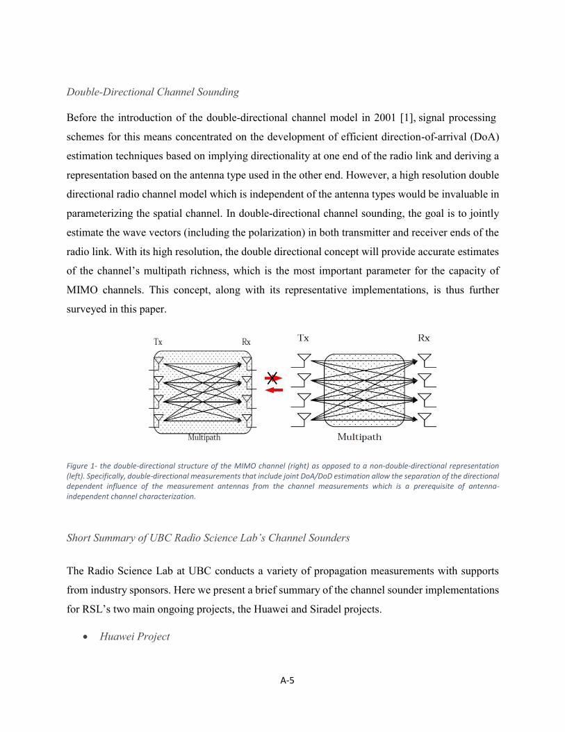
Double-Directional Channel Sounding
Before the introduction of the double-directional channel model in 2001 [1], signal processing
schemes for this means concentrated on the development of efficient direction-of-arrival (DoA)
estimation techniques based on implying directionality at one end of the radio link and deriving a
representation based on the antenna type used in the other end. However, a high resolution double
directional radio channel model which is independent of the antenna types would be invaluable in
parameterizing the spatial channel. In double-directional channel sounding, the goal is to jointly
estimate the wave vectors (including the polarization) in both transmitter and receiver ends of the
radio link. With its high resolution, the double directional concept will provide accurate estimates
of the channel’s multipath richness, which is the most important parameter for the capacity of
MIMO channels. This concept, along with its representative implementations, is thus further
surveyed in this paper.
Figure 1- the double-directional structure of the MIMO channel (right) as opposed to a non-double-directional representation (left). Specifically, double-directional measurements that include joint DoA/DoD estimation allow the separation of the directional dependent influence of the measurement antennas from the channel measurements which is a prerequisite of antenna-independent channel characterization.
Short Summary of UBC Radio Science Lab’s Channel Sounders
The Radio Science Lab at UBC conducts a variety of propagation measurements with supports
from industry sponsors. Here we present a brief summary of the channel sounder implementations
for RSL’s two main ongoing projects, the Huawei and Siradel projects.
Huawei Project
A-6
The Huawei project is mainly concerned with channel measurements at 28 to 38 GHz in the context
of system design for the emerging 5th Generation wireless cellular access. Specifically, since this
project does not assume MIMO operation and is rather concerned with investigating the nature of
the wireless channel in Millimeter-wave frequency bands per se, the channel parameters of interest
are the Power Delay Profile (PDP), coherence bandwidth, delay spread, and the angles of arrival
and departure (AoA and AoD). For this purpose, RSL is using a stepping correlator channel
sounder with Rubidium Frequency Standards, offering the advantage of long distance
measurements without using cables for TX-RX synchronization. The transmitter outputs a Binary
Phase-Shift Keying (BPSK) modulated pseudorandom noise (PN) sequence, triggered once per
second by a GPS using a Vector Signal Generator. Automated and controlled by a MATLAB
script, the receiver captures the IQ data using the VSA software and processes the captured data
in real time to compute the channel’s power delay profile and delay spread. Both Huawei and
Siradel projects require outdoor measurements in a 500 meter radius that resembles typical urban
environments. The field measurements are therefore conducted in UBC Vancouver campus.
Siradel Project
The same stepping correlator channel sounder system would be able to characterize dual-polarized
Multiple Input Multiple Output (MIMO) channels for Long-Term Evolution (LTE) applications,
as required by the terms of the Siradel project. This project involves wide-band polarimetric
outdoor macrocellular channel measurements at 2 GHz with the Short Pulse technique using a 1 ×
𝑁 linear array at the transmitter and an 𝑀 × 𝑀 synthesized array at the receiver. A suitable choice
of the antenna to be used in the arrays is the 1.9 GHz dual-polarized linear patch antenna. Two
orthogonal dual-polarized Pseudo Random Noise sequences are generated via a vector signal
generator at the TX, which is capable of high speed toggling between the polarizations using an
RF switch. These sequences are captured in the RX, consisting of a Velmex bi-slider realizing a
virtual array, and prospectively processed using the ESPRIT algorithm to obtain the AoA and AoD
information. The process is automated through a LabView interface, although a MATLAB script
has also been developed for establishing communication between the devices.
Objectives and Outline of This Survey

A-7
This appendix aims at summarizing briefly the current state of the art in DoA estimation, and
beamforming array implementation techniques for MIMO vector channel sounding that may be
relevant to UBC RSL’s Siradel project. Specifically, we will try to identify the current trends and
milestones in the field, and present a general idea of the gaps or limitations in the current work
that might be resolved through future research.
The appendix is organized as follows: Sec. 1 presents a review of algorithms for estimating the
Direction of Arrival and discusses two of the most popular high resolution algorithms, MUSIC
and ESPRT in more detail. A comparison between the performances of the high resolution
algorithms is further presented in Section 1. Section 2 discusses a review of different antenna array
types for beamforming in high resolution MIMO channel characterization, including planar and
spherical arrays, and presents an overview of the pros and cons of each. A brief discussion and
survey on double directional channel sounding using virtual arrays is presented in Section 3.
Finally, a number of suspected limitations of the current research work have been presented in
Section 4, along with recommendations to RSL for improvements in their implementation of the
Siradel project’s MIMO channel sounder system.

A-8
1. Review of Algorithms for Estimating the Direction of Arrival
This section briefly discusses methods and algorithms used in estimating the direction of arrival
(DoA) of a radio signal impinging on an array of antennas. In practice, the problem of DoA
estimation, which may be treated as equivalent to that of spectral estimation, is made difficult by
the fact that there is usually an unknown number of signals impinging on the array simultaneously,
each from unknown directions and with unknown amplitudes. Also, the received signals are always
corrupted by noise [16]. Nevertheless, this problem has been intensively studied for a long period
and many DoA estimation algorithms have been proposed. In a general sense, array-based
estimation techniques for directional of arrival can be divided into four categories: conventional
methods, subspace-based methods, maximum likelihood methods, and the integrated methods
combining the subspace-based techniques with property restoral techniques [8]. This section will
introduce the conventional methods and subsequently, will further elaborate on two most popular
subspace-based methods; namely, MUSIC and ESPRIT.
1.1. Conventional Methods
Conventional methods are based on classical beam forming principles; that is, given a certain
structure of an array of antennas, these methods try to steer the beam electronically in every
possible direction, just as it can be steered mechanically, and seek the direction of the maximum
received power by looking for the peak of the output power. They do not base their assumptions
on the statistical properties of signal and noise, nor do they make use of the nature of the
narrowband data model of the received signal vector. These methods thus require a large number
of elements to achieve high angular resolution and their resolution is highly dependent on the
physical size of the array aperture. Examples of conventional methods include Capon’s Minimum
Variance method and the Delay and Sum (Bartlett) method. The Minimum Variance method takes
into account uncertainties or variations associated with the array response, presumably due to
errors in AoA estimation or uncertainty in the array manifold. It then chooses the weights such
that the weighted array power output is minimized subject to a unity gain constraint in the desired
look direction. The downside to this method is that small variations in the array manifold can
greatly and adversely affect its performance. On the other hand, the Delay and Sum method
exploits the fact that there are different delays associated with signals impinging on the array from
A-9
different directions and the output power is maximized when the signals originate from the same
direction, due to the fact that they are more correlated and thus add constructively. This method
has many disadvantages, among which is the poor angular resolution associated with beam width
limitations, as this method does not distinguish delay differences less than the sampling period.
1.2. High Resolution Methods
In spite of the fact that the conventional beam forming methods are often successful and widely
used, they still suffer from lack of resolution, which in most cases is due to the fact that these
methods do not consider or exploit the structure of the data model. Schmidt [34] was the first to
develop a scheme with higher resolution using a more accurate data model for the case of sensor
arrays of arbitrary form. His proposed technique is the so-called MUSIC (Multiple SIgnal
Classification) algorithm, which is a high resolution technique based on exploiting the eigen
structure of the input covariance matrix. This method further assumes that the noises embedded in
each signal source are uncorrelated, and hence the correlation matrix is diagonal. SAGE (Space
Alternating Generalized Expectation Maximization [33], is another sub-space-based method which
supports joint estimation of DOA and DOD using complex radiation patterns of antennas as the
inputs for estimation. However, its convergence is not guaranteed in complicated propagation
environments, array calibration is a major problem in this method and also it is more sensitive to
noise than beam forming. The MUSIC algorithm, along with another algorithm called the
EStimation of Rotational Parameters via Rotational Invariance Technique (ESPRIT), formed the
core of a whole new class of DoA estimation methods called subspace-based methods. Basics of
the MUSIC and ESPRIT methods are discussed hereinafter.
1.2.1. MUSIC
The MUSIC algorithm is a high resolution signal parameter estimation algorithm which is able to
provide information about the number of incident signals, the Direction of Arrival (DoA) of each
signal, noise power, cross correlations between each pair of incident signals etc. This algorithm
decomposes the autocorrelation matrix into signal subspace and noise subspace and uses the
orthogonality between the two complementary subspaces to estimate the DoAs. While this
algorithm is of very high resolution and is adaptive to the shape of the antenna array, it requires
exact calibration of the antenna array. This point is further stressed in section 1.3.
10
In order to demonstrate the algorithm, assuming that 𝐾 far-field stationary and narrowband signals
impinge, in a linear sum fashion, on an array of 𝑀 sensors from direction angles 𝜽 =
[𝜃1, 𝜃2, … , 𝜃𝐾] which is corrupted by additive circular complex Gaussian white noise. The
received signal at the array output can be expressed as
𝑋(𝑡) = ∑ 𝒂(𝜃𝑘)𝑠𝑘(𝑡) + 𝒏(𝑡)
𝐾
𝑘=1
,
where 𝑠 = [𝑠1 𝑠2 𝑠3 … 𝑠𝐾] is the zero-mean vector of the incident signals, 𝒏(𝑡) is the noise vector
with zero mean and covariance matrix 𝜎𝑛2𝑰𝑀, and 𝑨(𝜃) is the array steering vector corresponding
to the directions of arrival.
The array covariance matrix is then given by
𝑅 = 𝐸[𝑋(𝑡)𝑋𝐻(𝑡)] = 𝑨𝑹𝒔𝒔𝑨𝑯 + 𝜎𝑛2𝑰𝑀 ,
where [ ]𝐻 denotes conjugation.
𝑹𝒔𝒔 has 𝐾 eigen vectors corresponding to the signal subspace and 𝑀 − 𝐾 eigen vectors associated
with the noise subspace. We can thus construct the 𝑀 × (𝑀 − 𝐾) subspace spanned by the noise
eigen vectors as
𝑉𝑁 = [𝑉1 𝑉2 𝑉3 … 𝑉𝑀−𝐾] .
It can be shown that the noise subspace eigen vectors are orthogonal to the array steering vectors
at the angles of arrival 𝜃1, 𝜃2, … , 𝜃𝐾 and the MUSIC pseudo-spectrum is thus given by
𝑃𝑀𝑈𝑆𝐼𝐶(𝜃) =1
𝒂𝑯(𝜃)𝑉𝑁𝑉𝑁𝐻𝒂(𝜃)
.
The above equation is a measure of the closeness of the array manifold to the signal subspace.
Since the product 𝑉𝑁𝑉𝑁𝐻 represents projection on the noise subspace, the denominator in the above
equation is a measure of the distance between the array’s steering vector 𝒂(𝜃) and the estimated
noise subspace 𝑉𝑁. The more the two vectors are orthogonal, the less will the denominator become,
giving rise to peaks in the MUSIC pseudo-spectrum. The K largest peaks in the spectrum will
correspond to the actual directions of arrival 𝜃1, 𝜃2, … , 𝜃𝐾 .
11
Various modifications to the MUSIC algorithm have been proposed to increase its resolution
performance and decrease the computational complexity. One such improvement is the Root-
MUSIC algorithm developed by Barbell [35], which is based on polynomial rooting and provides
higher resolution, but is applicable only to a uniform spaced linear array. [33] CYCLIC MUSIC
which exploits the spectral coherence properties of the signal to improve the performance of the
conventional MUSIC algorithm has been also proposed [36]. Fast Subspace Decomposition
techniques have also been studied to decrease the computational complexity of MUSIC [37].
1.2.2. ESPRIT
The ESPRIT algorithm is another subspace-based scheme developed by Roy et al. [17] which, not
only is more efficient than MUSIC in terms of computational burden (since it does not involve an
exhaustive search among all possible steering vectors), but also does not place stringent
requirements on array calibration (since it does not require that the array manifold be precisely
known). ESPRIT derives its advantage by exploiting the rotational invariance property in the
signal subspace which is created by two arrays with a structure that is invariant to translation. That
is, it assumes an array composed of two identical sub-arrays (matched pairs or doublets) separated
from one another by a fixed distance, denoted from now on by 𝑑.
Assuming that there are 𝐾 < 𝑀 narrowband sources centered at the frequency 𝑓0, the signal
induced on each subarray is given by
𝑥1(𝑡) = 𝑨𝑠(𝑡) + 𝒏𝟏(𝑡) and
𝑥2(𝑡) = 𝑨𝚽𝒔(𝑡) + 𝒏𝟐(𝑡) ,
where Φ = 𝑑𝑖𝑎𝑔(𝑒𝑗𝑘𝑑𝑠𝑖𝑛(𝜃1) 𝑒𝑗𝑘𝑑𝑠𝑖𝑛(𝜃2) … 𝑒𝑗𝑘𝑑𝑠𝑖𝑛(𝜃𝐾)) is a diagonal matrix whose elements
represent the phase delays between the doublet sensors. Basically, ESPRIT exploits the rotational
invariance of the signal subspace induced by the translational invariance of the sensor array.
Creating the signal subspace for the two subarrays results in two matrices 𝑉1 and 𝑉2. Since the
arrays are related to each other by translation, the subspaces of eigenvectors are related by a unique
nonsingular transformation matrix Ψ such that 𝑉1Ψ = 𝑉2. There must also exist a unique
nonsingular transformation matrix 𝑇 such that 𝑉1 = 𝐴𝑇 and 𝑉2 = 𝐴Φ𝑇, so that we can finally
derive

12
𝑇ΨT−1 = Φ .
Therefore, the eigenvalues of Ψ must be equal to the diagonal elements of Φ such that
𝜆1 = 𝑒𝑗𝑘𝑑𝑠𝑖𝑛(𝜃1) , 𝜆2 = 𝑒𝑗𝑘𝑑𝑠𝑖𝑛(𝜃2) , … , 𝜆𝐾 = 𝑒𝑗𝑘𝑑𝑠𝑖𝑛(𝜃𝐾)
Once the eigen values of Ψ are calculated, the angles of arrival are estimated as 𝜃𝑖 =
sin−1 (arg(𝜆𝑖)
𝑘𝑑) .
1.3. Performance Comparison of high resolution DoA estimation algorithms
Here we present a brief comparison of how well the aforementioned methods perform in terms of
a number of criteria; namely, the number of resolvable signals, whether the method addresses
coherent signals, accuracy, resolution, need for calibration, computational efficiency, and whether
the algorithm can be implemented in multidimensional arrays.
Number of Resolvable Signals: In MUSIC we assumed that the number of elements, 𝑀,
was greater than the number of signals, 𝐾. This is required because MUSIC depends on
the existence of a noise subspace. Therefore with 𝑀 elements, MUSIC can resolve a
maximum of (𝐾 − 1) signals. In ESPRIT, a similar argument holds.
Addressing Coherent Signals: coherent signals are defined as signals with high correlation.
While MUSIC fails to treat these kinds of signals, ESPRIT and Root-MUSIC have
overcome this problem.
Accuracy: all the adaptive techniques have demonstrated similar accuracies in determining
angles of arrival [16], while MUSIC slightly outperforms ESPRIT in this sense. The
accuracy of all the methods can be increased by increasing the number of the array
elements, increasing the signal to noise ratio, and increasing the number of samples.
Resolution: For MUSIC, the ability to resolve a scenario in which the impinging signals
are closely separated in angles of arrival depends on the signal to noise ratio at the input of
the array and the total number of samples of data (proportional to the observation interval)
used to compute the MUSIC spectrum [8]. Furthermore, the resolution also depends on the
number of elements in the array, while ESPRIT does not exhibit this problem.
13
Sensitivity to Calibration: as mentioned before, errors in array element spacing and
calibration measurements for the steering vectors will lead to distortions in the MUSIC
spectrum [8].
Computational Efficiency: as discussed previously, ESPRIT eliminates the exhaustive
spectral search procedure inherent in MUSIC by exploiting the eigen value decomposition
approach, and therefore drastically reduces the computational burden. Also, the Root-
MUSIC algorithm enjoys a substantially reduced computational complexity and an
improved threshold estimation performance as compared to MUSIC [32].
Implementation in Multidimensional Arrays: It has been proven that MUSIC and ESPRIT
are both convenient and reliable for use in two dimensional DoA estimation. However,
Root-MUSIC is only applicable to uniform linear arrays (ULA) or non-uniform linear
arrays whose sensors are restricted to lie on a uniform grid [38]. According to the
simulation results of [39], the MUSIC algorithm shows slightly better performance than
ESPRIT in the two dimensional case, and for both algorithms, the Root Mean Square Error
of the azimuth angles are smaller than those of the elevation angles.
14
2. Review of Different Beamforming Antenna Array
Architectures for MIMO Channel Sounding
The spatial features of the MIMO channel response are captured by antenna arrays. An array is a
configuration of multiple antenna elements arranged and interconnected in space to obtain a
directional radiation pattern. It is possible, using phased antenna arrays, to electronically scan the
main beam and place nulls in any direction by changing the phase of the exciting currents in each
of the antenna elements. It is also possible, through antenna arrays, to obtain high resolution
measures of the directional spreading of the MIMO channel at the transmitter and receiver sides.
Sophisticated antenna architecture design is required to achieve high DoD/DoA resolution in
MIMO channel sounding. This has to be developed with mechanically and electrically stable
construction and precise calibration. Since there is always a tradeoff between various
specifications including resolution, measurement time, availability and costs, there is a wide
variety of useful antenna array architectures. In the following, we summarize some design
architectures and considerations.
2.1. Antenna Array Configurations
2.1.1. Uniform Linear Array (ULA)
The classical uniform linear arrays consist of M elements placed linearly with uniform spacing.
Due to their simplicity and applicability to many DoA estimation algorithms, ULA’s are widely
used in array designs; however, one of the biggest drawbacks of the uniform linear array is that it
can only resolve the azimuthal angle of the impinging waves, and is thus ambiguous in the
elevation. Also, its visibility area is limited if the distance between the elements is more than 𝜆/2.
The effective array aperture depends on the DoD/DoA and the resolution capability is not uniform
[40].

15
Figure 2 – left: a Uniform Linear Array (ULA) configuration, right: a Uniform Circular Array (UCA) configuration
2.1.2. Uniform Rectangular Array (URA)
This topology allows acquisition in both elevation and azimuth angles. In addition to azimuthal
resolution, URA’s also allow for elevation angle estimation. 2-D Unitary ESPRIT algorithms are
well suited with this type of array due to its regular rectangular structure. Moreover, 2-D spatial
smoothing can be carried out easily in order to cope with coherent waves (which is especially
important in complicated micro- or picocell environments). A famous example of the application
of this type of array is in the RUSK wideband vector channel sounder employed in [1].
Figure 3 – A Uniform Rectangular Array (URA) configuration
2.1.3. Uniform Circular Array (UCA)
In this configuration, M identical elements are uniformly distributed around a circle. This structure
can provide constant DOA estimation within the range of 0 ° to 360 ° and resolve two-dimensional
angular sources of signal. This architecture’s angular resolution capability is fairly uniform.
However, though this system can be used to characterize the delay-angular properties of the
channel with high resolution in azimuth (<5º), the resolution in elevation is poor (>5º) and there is
ambiguity in the elevation domain.
2.1.4. Spherical and Semi-spherical Arrays
16
An optimal way for scanning the whole 4𝜋 angle in space would be to use an array mounted on a
spherical surface. However, the geometry of the sphere does not allow uniform distribution of any
number of elements on the sphere. Therefore, non-uniform inter-element distances and various
relative polarization orientations of adjacent elements will complicate the design of spherical
arrays. Moreover, optimization of the inter-element distance for circular and spherical arrays (or
of the diameter in case of a fixed number of antenna elements) is required to minimize the side-
lobes of the angular correlation function to reduce the probability of outliers in iterative parameters
search. This typically leads to inter-element distances smaller than half a wavelength [41].
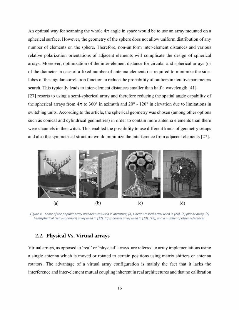
[27] resorts to using a semi-spherical array and therefore reducing the spatial angle capability of
the spherical arrays from 4𝜋 to 360° in azimuth and 20° - 120° in elevation due to limitations in
switching units. According to the article, the spherical geometry was chosen (among other options
such as conical and cylindrical geometries) in order to contain more antenna elements than there
were channels in the switch. This enabled the possibility to use different kinds of geometry setups
and also the symmetrical structure would minimize the interference from adjacent elements [27].
Figure 4 – Some of the popular array architectures used in literature, (a) Linear Crossed Array used in [24], (b) planar array, (c) hemispherical (semi-spherical) array used in [27], (d) spherical array used in [13], [29], and a number of other references.
2.2. Physical Vs. Virtual arrays
Virtual arrays, as opposed to ‘real’ or ‘physical’ arrays, are referred to array implementations using
a single antenna which is moved or rotated to certain positions using matrix shifters or antenna
rotators. The advantage of a virtual array configuration is mainly the fact that it lacks the
interference and inter-element mutual coupling inherent in real architectures and that no calibration
(a) (b) (c) (d)

17
between the array elements is needed due to absence of neighboring elements. Moreover, the shape
of the array can be arbitrary and flexible with respect to the application. It is also less expensive
and easily reconfigurable from a hardware point of view. However, using arrays has the
disadvantage of the slow measurement procedure: considering all the TX-RX positions, all the
frequency samples taken, and all required temporal samples, positioning the element via a step
motor might take longer periods than desired. Moreover, phase continuity in virtual arrays is a
major concern when defining the direction of arrival [19].
2.3. Choice of Antenna Array Architectures
Antenna element design is mainly determined by requirements for bandwidth, uniform beam
patterns, low inter-element coupling and polarization resolution. On the other hand, array design
mainly determines the super-resolution algorithm which can be applied, the resulting accuracy and
resolution as well as the resolvable spatial dimensions in terms of azimuth and elevation angles.
Regular planar array structures (i.e. uniform linear arrays or uniform rectangular arrays (URA) can
be used for 1-D (azimuth) and 2-D (azimuth/elevation) resolution, respectively. These require
antenna elements with some directionally selective characteristic in order to remove the inherent
front/back ambiguity of planar arrays. Moreover, a non-linear transformation from
azimuth/elevation to the row/column element phase response is involved. This restricts the
resolvable range to a sector of less than 180° (typically 120°).
In contrast, with circular antenna arrays the complete azimuth range of 360° can be covered.
Realizations are given by the uniform circular array (UCA), the uniform circular patch array
(UCPA) and the circular uniform beam array (CUBA). If elevation is of interest, vertically stacked
UCPA or even spherical patch arrays (SPA) are possible solutions.
Double directional estimation requires arrays at both sides of the link and MIMO operation of the
sounder. For cellular system consideration, a combination of planar and circular arrays is adequate,
whereas for ad-hoc peer-to-peer networks identical circular arrays are most preferable [40].
Additionally, high and reliable resolution in terms of separation capability of closely spaced paths
and low probability of outliers requires an antenna architecture which offers a minimum antenna
array aperture size in the respective spatial dimension, including a minimum number of antenna
elements, low antenna element coupling, and precise calibration. This has also to include the
antenna switches and feeder cables.
18
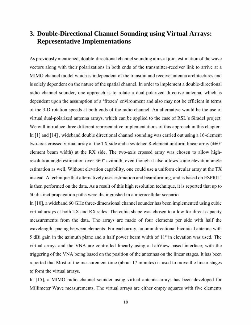
3. Double-Directional Channel Sounding using Virtual Arrays:
Representative Implementations
As previously mentioned, double-directional channel sounding aims at joint estimation of the wave
vectors along with their polarizations in both ends of the transmitter-receiver link to arrive at a
MIMO channel model which is independent of the transmit and receive antenna architectures and
is solely dependent on the nature of the spatial channel. In order to implement a double-directional
radio channel sounder, one approach is to rotate a dual-polarized directive antenna, which is
dependent upon the assumption of a ‘frozen’ environment and also may not be efficient in terms
of the 3-D rotation speeds at both ends of the radio channel. An alternative would be the use of
virtual dual-polarized antenna arrays, which can be applied to the case of RSL’s Siradel project.
We will introduce three different representative implementations of this approach in this chapter.
In [1] and [14] , wideband double directional channel sounding was carried out using a 16-element
two-axis crossed virtual array at the TX side and a switched 8-element uniform linear array (±60°
element beam width) at the RX side. The two-axis crossed array was chosen to allow high-
resolution angle estimation over 360" azimuth, even though it also allows some elevation angle
estimation as well. Without elevation capability, one could use a uniform circular array at the TX
instead. A technique that alternatively uses estimation and beamforming, and is based on ESPRIT,
is then performed on the data. As a result of this high resolution technique, it is reported that up to
50 distinct propagation paths were distinguished in a microcellular scenario.
In [10], a wideband 60 GHz three-dimensional channel sounder has been implemented using cubic
virtual arrays at both TX and RX sides. The cubic shape was chosen to allow for direct capacity
measurements from the data. The arrays are made of four elements per side with half the
wavelength spacing between elements. For each array, an omnidirectional biconical antenna with
5 dBi gain in the azimuth plane and a half power beam width of 11º in elevation was used. The
virtual arrays and the VNA are controlled linearly using a LabView-based interface; with the
triggering of the VNA being based on the position of the antennas on the linear stages. It has been
reported that Most of the measurement time (about 17 minutes) is used to move the linear stages
to form the virtual arrays.
In [15], a MIMO radio channel sounder using virtual antenna arrays has been developed for
Millimeter Wave measurements. The virtual arrays are either empty squares with five elements

19
along each edge (a total of 16 elements – chosen as a compromise between accuracy in the angular
domain and the duration of the measurements), or full squares with 5 × 5 elements (chosen in order
to have a larger number of channels, which is required to calculate the channel capacities).
Measurements in the LOS and the LOS obstructed scenarios with a 16-element array at both the
TX and the RX are reported, as well as measurements in NLOS using a 25-element array at both
the transmitter and receiver. The MIMO channel capacity is calculated for various numbers of
elements per array: [2 · 2], [3 · 3], [4 · 4], and [5 · 5]. It is seen that the capacity increases almost
linearly as a function of the number of elements, as stated in theory.

20
4. Conclusion And Recommendations
Current widespread interest in smart antennas as promises for higher capacity and better quality of
service in the next generation wireless systems has led to investigations in different techniques for
parameterization and characterization of the spatial radio channel. Towards this end, different
novel antenna architectures and high resolution space-time signal processing algorithms have since
been used in measurement-based channel sounding techniques. This survey presented a brief
summary of the current state of the art in these areas.
One area which is open for further investigations is the tracking of radio channel parameters, or
more precisely, the estimation of deterministic changes of channel parameters. The variations of
the structural path parameters are closely related to the movement of objects influencing the radio
channel. A first promising attempt has been made to estimate the parameter changes of the
propagation path parameters using a linear model, but this area has generally been left out in
characterization of channel parameters.
A further prospective research topic can be the optimal antenna array structure for channel
sounding applications. Closely related to this issue is the calibration of antenna arrays, e.g., the
estimation of the antenna array model especially the EADF. Since the upcoming channel sounding
systems will have a larger bandwidth, the frequency dependence of the array response, e.g., the
EADF is another interesting field which must be investigated in future works.
Finally, it is worth adding here that a virtual array sliding correlator implementation, along with
ESPRIT as the signal processing algorithm, is recommended to RSL for use in their channel
sounder for the Siradel project. The sliding correlator offers the distinct advantage of bandwidth
compression through temporal dilation, making it an ideal approach for measuring the huge
bandwidths of the ultra-wideband channel. This implementation also has the advantages of low
cost, low losses, higher gain antennas, ease of reconfiguration, and robustness due to the use of
Direct Sequence Spread Spectrum signals. DSSS also provides improved measurement dynamic
range and low peak power levels, which allow the channel sounder to perform noninvasive
measurements at interference-sensitive channels.
It is imposed by the Nyquist criterion that the element separation in antenna arrays be less than or
equal to half a wavelength, which is about 8 cm. Therefore, an inter-element separation of 2-8 cm
21
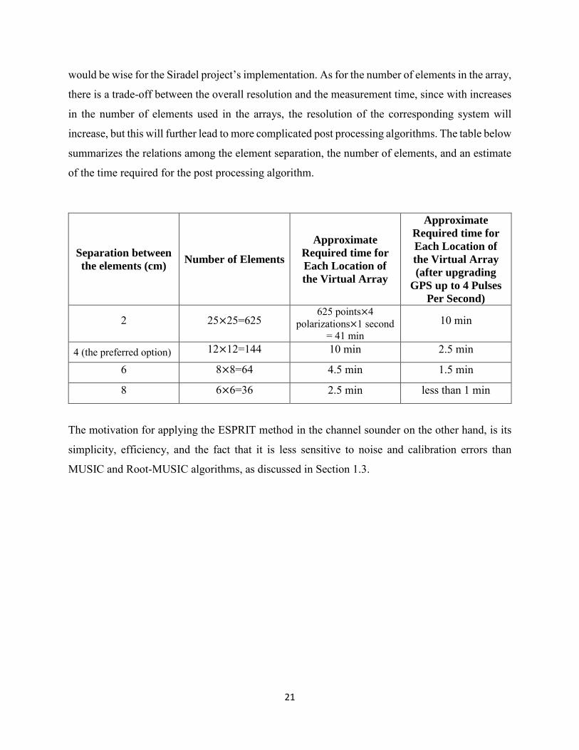
would be wise for the Siradel project’s implementation. As for the number of elements in the array,
there is a trade-off between the overall resolution and the measurement time, since with increases
in the number of elements used in the arrays, the resolution of the corresponding system will
increase, but this will further lead to more complicated post processing algorithms. The table below
summarizes the relations among the element separation, the number of elements, and an estimate
of the time required for the post processing algorithm.
Separation between
the elements (cm) Number of Elements
Approximate
Required time for
Each Location of
the Virtual Array
Approximate
Required time for
Each Location of
the Virtual Array
(after upgrading
GPS up to 4 Pulses
Per Second)
2 25×25=625 625 points×4
polarizations×1 second = 41 min
10 min
4 (the preferred option) 12×12=144 10 min 2.5 min
6 8×8=64 4.5 min 1.5 min
8 6×6=36 2.5 min less than 1 min
The motivation for applying the ESPRIT method in the channel sounder on the other hand, is its
simplicity, efficiency, and the fact that it is less sensitive to noise and calibration errors than
MUSIC and Root-MUSIC algorithms, as discussed in Section 1.3.
22
References
[1] M. Steinbauer, A. F. Molisch, and E. Bonek, “The double-directional radio channel,” IEEE
Antennas Propag. Mag., vol. 43, no. 4, pp. 51-63, Aug. 2001.
[2] S. Salous, “Radio Propagation Measurement and Channel Modelling.” Wiley, 2013, pp.
225-231. (Sec. 4.16 - Single and Multiple Antenna Sounder Architectures.)
[3] M. Landmann, M. Kaske and R. S. Thoma, “Impact of incomplete and inaccurate data
models on high resolution parameter estimation in multidimensional channel sounding.”
IEEE Trans. Antennas Propag.,vol. 60, no. 2, pp. 557-573, Feb. 2012.
[4] J. Fuhl, J-P Rossi, and E. Bonek, “High-resolution 3D direction-of-arrival determination
for urban mobile radio, IEEE Trans. Antennas Propag., vol. 45, no. 4, pp. 672-682, Apr.
1997.
[5] A. Kuchar, J-P Rossi and E. Bonek, “Directional macro-cell channel characterization from
urban measurements,” IEEE Trans. Antennas Propag., vol. 48, no. 2, pp. 137-146, Feb.
2000.
[6] R.B. Ertel, P. Cardieri, K.W. Sowerby, T.S. Rappaport, J.H. Reed, “Overview of Spatial
Channel Models for Antenna Array Communication Systems,” IEEE Personal
Communications, Vol. 5, No. 1, pages 10-22, 1998.
[7] A. F. Molisch and F. Tufvesson, “MIMO channel capacity and measurements,” in Smart
Antennas - State of the Art (T. Kaiser, Ed.), EURASIP Book Series, 2005
[8] R. Muhamed, T. S. Rappaport, "Direction of Arrival Estimation Using Antenna Arrays,"
Technical Report, MPRG-TR-96-03, Virginia Tech, January 1996.
[9] Kalliola, K.; Laitinen, H.; Vainikainen, P.; Toeltsch, M.; Laurila, J.; Bonek, E., "3-D
double-directional radio channel characterization for urban macrocellular applications,"
Antennas and Propagation, IEEE Transactions on , vol.51, no.11, pp.3122,3133, Nov.
2003.
[10] Ranvier, S.; Kyro, M.; Haneda, K.; Mustonen, T.; Icheln, C.; Vainikainen, P., "VNA-based
wideband 60 GHz MIMO channel sounder with 3-D arrays," Radio and Wireless
Symposium, 2009. RWS '09. IEEE , vol., no., pp.308,311, 18-22 Jan. 2009.
23
[11] R. S. Thomä, M. Landmann, A. Richter, U. Trautwein, “Multidimensional High Resolution
Channel Sounding Measurement,” in Smart Antennas – State of the Art, (T. Kaiser, Ed.)
EURASIP Book Series, 2005.
[12] Krim, H.; Viberg, M., "Two decades of array signal processing research: the parametric
approach," Signal Processing Magazine, IEEE , vol.13, no.4, pp.67,94, Jul 1996.
[13] Kalliola, K.; Laitinen, H.; Vaskelainen, L.I; Vainikainen, P., "Real-time 3-D spatial-
temporal dual-polarized measurement of wideband radio channel at mobile station,"
Instrumentation and Measurement, IEEE Transactions on , vol.49, no.2, pp.439,448, Apr
2000.
[14] Steinbauer, M.; Hampicke, Dirk; Sommerkorn, G.; Schneider, Axel; Molisch, AF.; Thoma,
R.; Bonek, E., "Array measurement of the double-directional mobile radio channel,"
Vehicular Technology Conference Proceedings, 2000. VTC 2000-Spring Tokyo. 2000
IEEE 51st , vol.3, no., pp.1656,1662 vol.3, 2000.
[15] Ranvier, S.; Kivinen, Jarmo; Vainikainen, P., "Millimeter-Wave MIMO Radio Channel
Sounder," Instrumentation and Measurement, IEEE Transactions on , vol.56, no.3,
pp.1018,1024, June 2007.
[16] R. Adve, “Direction of Arrival Estimation”, University of Toronto, Available for download
at http://www.comm.utoronto.ca/~rsadve/Notes/DOA.pdf.
[17] R. Roy and T. Kailath, “ESPRIT Estimation of Signal Parameters via Rotational Invariance
Techniques,” IEEE Transactions on Acoustics, Speech, and Signal Processing, ASSP37,
July 1989, pp. 984995.
[18] Richter, A., "Estimation of radio channel parameters: Models and algorithms," Ph.D.
Dissertation, Technische Universität Ilmenau, Ilmenau, Germany, 2005.
[19] Laurila, J.; Kalliola, K.; Toeltsch, M.; Hugl, K.; Vainikainen, P.; Bonek, E., "Wideband
3D characterization of mobile radio channels in urban environment," Antennas and
Propagation, IEEE Transactions on , vol.50, no.2, pp.233,243, Feb 2002.
[20] H. Farhat, G. Grunfelder, A. Carcelen and G. El Zein, "MIMO Channel Sounder at 3.5
GHz: Application to WiMAX System," Journal of Communications, vol. 3, no.5, pp. 23-
30, 2008.
[21] Singh H., Jha R.M., “Trends in adaptive array processing”, International Journal Antennas
Propag. 1–20, 2012.

24
[22] Stromberg, F., "Virtual Antenna Arrays Results and Ongoing Studies", Radio
Communications Systems Lab. Department of Signals, Sensors and Systems, Royal
Institute of Technology (KTH), SE-164 40 Kista Sweden.
[23] Shafi, M.; Min Zhang; Moustakas, AL.; Smith, P.J.; Molisch, AF.; Tufvesson, F.; Simon,
S.H., "Polarized MIMO channels in 3-D: models, measurements and mutual information,"
Selected Areas in Communications, IEEE Journal on , vol.24, no.3, pp.514,527, March
2006.
[24] Kwakkernaat, M. R J A E; De Jong, Y. L C; Bultitude, R. J C; Herben, M. H A J, "High-
Resolution Angle-of-Arrival Measurements on Physically-Nonstationary Mobile Radio
Channels," Antennas and Propagation, IEEE Transactions on , vol.56, no.8, pp.2720,2729,
Aug. 2008.
[25] Lal C. Godara, "Application of Antenna Arrays to Mobile Communications, Part II: Beam-
Forming and Direction-of-Arrival Considerations", Proc. of the IEEE, Vol. 85, No. 8, pp.
1195-1245, 1997.
[26] Xiong, Hao (2013) “Antenna array geometries and algorithms for direction of arrival
estimation” MRes thesis, University of Nottingham.
[27] Kolmonen, V. -M; Kivinen, J.; Vuokko, L.; Vainikainen, P., "5.3 GHz MIMO radio
channel sounder," Instrumentation and Measurement Technology Conference, 2005.
IMTC 2005. Proceedings of the IEEE , vol.3, no., pp.1883,1888, 16-19 May 2005.
[28] M Beach, D McNamara, P Karlsson, "Development of a Channel Measurement System for
Multiple-Input Multiple -Output (MIMO) Applications", 1ST Mobile Summit, pp497-501
12. M 2000.
[29] Sulonen, K.; Suvikunnas, Pasi; Vuokko, L.; Kivinen, Jarmo; Vainikainen, P., "Comparison
of MIMO antenna configurations in picocell and microcell environments," Selected Areas
in Communications, IEEE Journal on , vol.21, no.5, pp.703,712, June 2003.
[30] Bhobe, AU.; Perini, P.L., "An overview of smart antenna technology for wireless
communication," Aerospace Conference, 2001, IEEE Proceedings. , vol.2, no.,
pp.2/875,2/883 vol.2, 2001.
[31] Yaqoob, M.A; Tufvesson, F.; Mannesson, A; Bernhardsson, B., "Direction of arrival
estimation with arbitrary virtual antenna arrays using low cost inertial measurement units,"

25
Communications Workshops (ICC), 2013 IEEE International Conference on , vol., no.,
pp.79,83, 9-13 June 2013.
[32] A. Vesa, “Direction of arrival estimation using music and root-music algorithm”, in 18th
Telecommunication forum TELFOR, November 2010.
[33] B. Fleury, D. Dahlhaus, R. Heddergott, and M. Tschudin, “Wideband Angle of Arrival
Estimation using the SAGE ,Algorithm,” IEEE Conference Proceedings of ISSSTA ’96,
1996, pp. 7985.
[34] R. O. Schmidt, “Multiple emitter location and signal parameter estimation,” in Proc.
RADC Spectrum Estimat. Workshop, Griffiths AFB, NY, May 1979, pp. 243–258.
[35] Barabell, A, "Improving the resolution performance of eigenstructure-based direction-
finding algorithms," Acoustics, Speech, and Signal Processing, IEEE International
Conference on ICASSP '83. , vol.8, no., pp.336,339, Apr 1983.
[36] Schell, S.V.; Calabretta, R.A; Gardner, W.A; Agee, B.G., "Cyclic MUSIC algorithms for
signal-selective direction estimation," Acoustics, Speech, and Signal Processing, 1989.
ICASSP-89., 1989 International Conference on , vol., no., pp.2278,2281 vol.4, 23-26 May
1989.
[37] Guanghan Xu; Kailath, T., "Fast subspace decomposition," Signal Processing, IEEE
Transactions on , vol.42, no.3, pp.539,551, Mar 1994.
[38] M. Rubsamen, A. Gershman, “Root-MUSIC Based Direction-of- Arrival Estimation
Methods for Arbitrary Non-Uniform Arrays,” IEEE Intern. Conf. on Acoustics, Speech
and Signal Processing.
[39] Xiang Gu, Yunhua Zhang, “Effects of amplitude and phase errors on 2- D MUSIC and 2-
D ESPRIT algorithms in ISAR imaging”, Synthetic Aperture Radar, 2009. APSAR 2009.
2nd Asian-Pacific Conference on Digital Object , Page(s): 634 – 638, 2009.
[40] M. Landmann, “Limitations of experimental channel characterisation,” Doctoral Thesis,
Ilmenau University of Technology, Ilmenau, Germany, Mar. 2008.
[41] Tan C. M., Landmann M., Richter A., Pesik L., Beach M., Schneider C., Thoma R., and
Nix A., “On the Application of Circular Arrays in Direction Finding Part II: Experimental
evaluation on SAGE with different circular arrays,” in 1st Annual COST 273 Workshop,
Espoo, Finland, May 2002.