Embed Size (px)
Citation preview
NIST GCR 17-014
A Study on the Effect of Repeat Moderate Intensity Radiant
Exposures on SCBA Facepiece Properties
Gavin P. Horn
Richard M. Kesler John W. Regan
IFSI Research, Illinois Fire Service Institute, University of Illinois at Urbana-Champaign
Daniel Madrzykowski
UL Firefighter Safety Research Institute
This publication is available free of charge from: https://doi.org/10.6028/NIST.GCR.17-014

NIST GCR 17-014
A Study on the Effect of Repeat Moderate Intensity Radiant
Exposures on SCBA Facepiece Properties
Prepared for
U.S. Department of Commerce Fire Research Division, Engineering Laboratory
National Institute of Standards and Technology Gaithersburg, MD 20899-8661
By
Gavin P. Horn Richard M. Kesler
John W. Regan IFSI Research, Illinois Fire Service Institute, University of Illinois at Urbana-Champaign
Daniel Madrzykowski UL Firefighter Safety Research Institute
This publication is available free of charge from:
https://doi.org/10.6028/NIST.GCR.17-014
July 2017
U.S. Department of Commerce Wilbur L. Ross, Jr., Secretary
National Institute of Standards and Technology
Kent Rochford, Acting NIST Director and Under Secretary of Commerce for Standards and Technology

Disclaimer This publication was produced as part of contract 60NANB14D309 with the National Institute of Standards and Technology. The contents of this publication do not necessarily reflect the views or policies of the National Institute of Standards and Technology or the US Government. Certain commercial equipment, instruments, or materials are identified in this paper for completeness and to foster understanding. Such identification does not imply recommendation or endorsement by the National Institute of Standards and Technology, nor does it imply that the materials or equipment identified are necessarily the best available for the purpose.


i
This publication is available free of charge from: https://doi.org/10.6028/N
IST.GC
R.17-014
Abstract
Firefighting personal protective equipment (PPE) has evolved through significant technological improvements over the past half century. Enhanced thermal protection from modern PPE and the introduction of self-contained breathing apparatus (SCBA) has enabled firefighters to work longer and more efficiently in immediately dangerous to life or health environments. Despite these advancements, performance limitations remain in many parts of the turnout gear ensemble. In particular, the SCBA mask represents a critical potential failure point, as a compromised lens can result in loss of vision, facial and airway burns, and other injuries associated with the inhalation of products of combustion. It has been speculated that repeated exposures to mild to moderate thermal exposures may cause a change in the mechanical properties of the SCBA face piece lens material, potentially weakening the mask and precipitating a catastrophic failure of the lens. To address this concern, a new laboratory instrument has been constructed to provide repeatable cyclic thermal exposure for SCBA facepieces building on the existing NIST radiant panel apparatus that has recently been adopted by the NFPA 1981 standard. SCBA facepieces that were worn in the field were also harvested to allow important comparison with changes caused by typical fire service use conditions.
With this automated system SCBA facepieces were exposed to 1 kW/m2, 2 kW/m2 and 5 kW/m2 radiant heat flux exposures (NIST Thermal Classes I, II and III, respectively) for one, 10 and 100 cycles. Repeated exposure to Class I and II heat fluxes do not have a significant effect on thermal damage or mechanical properties compared to unexposed samples. While a single exposure to the 5 kW/m2 condition also resulted in no visible thermal damage or mechanical changes, microcracking was consistently observed by 10 cycles and continued to extend in the 100 cycle samples. Though visible damage was evident after 10 cycles, mechanical properties were not affected. On the other hand, substantial reductions in ductility were noted after 100 cycles, with changes in mechanical properties that were similar to those measured in the field worn samples. In field worn samples where significant reductions in quasi-static tensile properties are noted, significant reduction in dynamic energy absorption were also measured. The 5 kW/m2 – 100 cycle samples that resulted in the most significantly reduced ductility were harvested from the area where visible surface microcracking was present. However, samples from the edges of the exposed area, where no visible damage was noted, also demonstrated smaller but significant reduction in ductility. Thus, there does not appear to be a one-to-one correlation between visual indications of thermal damage and reduced mechanical properties. However, if an SCBA facepiece shows visual indications of thermal damage or has been repeatedly exposed to Class III environments, the unit should be closely inspected and replacement considered.
Keywords: SCBA; facepiece; fire fighter equipment; heat flux; mechanical testing; failure analysis
ii
This publication is available free of charge from: https://doi.org/10.6028/N
IST.GC
R.17-014
Table of Contents Abstract and Keywords ........................................................................................................... i
1. Introduction ..................................................................................................................... 1 1.1. Current state of knowledge .......................................................................................... 1 1.2. Goals ............................................................................................................................ 5
2. Experimental Details ....................................................................................................... 6 2.1. Radiant panel apparatus ............................................................................................... 6 2.2. Modification for cyclic exposures ............................................................................... 7
2.2.A. Shield construction ................................................................................................. 7 2.2.B. Frame design ........................................................................................................... 9 2.2.C. Translation ............................................................................................................ 11 2.2.D. System design and validation ............................................................................... 12
2.3. Exposure experiments ............................................................................................... 14 2.4. Mechanical testing........................................................................................................ 15
2.4.A. Specimen............................................................................................................... 15 2.4.B. Specimen harvesting ............................................................................................. 16 2.4.C. Uniaxial tension test apparatus ............................................................................. 17 2.4.D. Impact test apparatus ............................................................................................ 19
2.4. Statistics ..................................................................................................................... 20
3. Results and Discussion .................................................................................................. 21 3.1. Facepiece temperatures during repeated radiant exposures ...................................... 21 3.2. Thermal damage ........................................................................................................ 22 3.3. Quasistatic uniaxial tensile test results ...................................................................... 26 3.4. Impact test results ...................................................................................................... 28 3.5. Summary of effects of repeated thermal exposures on mechanical properties ......... 31 3.6. Future potential investigations .................................................................................. 32
4. Summary and Conclusions ........................................................................................... 34
5. Acknowledgements ........................................................................................................ 35
6. References ....................................................................................................................... 36
Appendix A – Assembly Drawings ...................................................................................... 38
Appendix B – Microcontroller Code ................................................................................... 42
1
This publication is available free of charge from: https://doi.org/10.6028/N
IST.GC
R.17-014
1. Introduction 1.1. Current state of knowledge
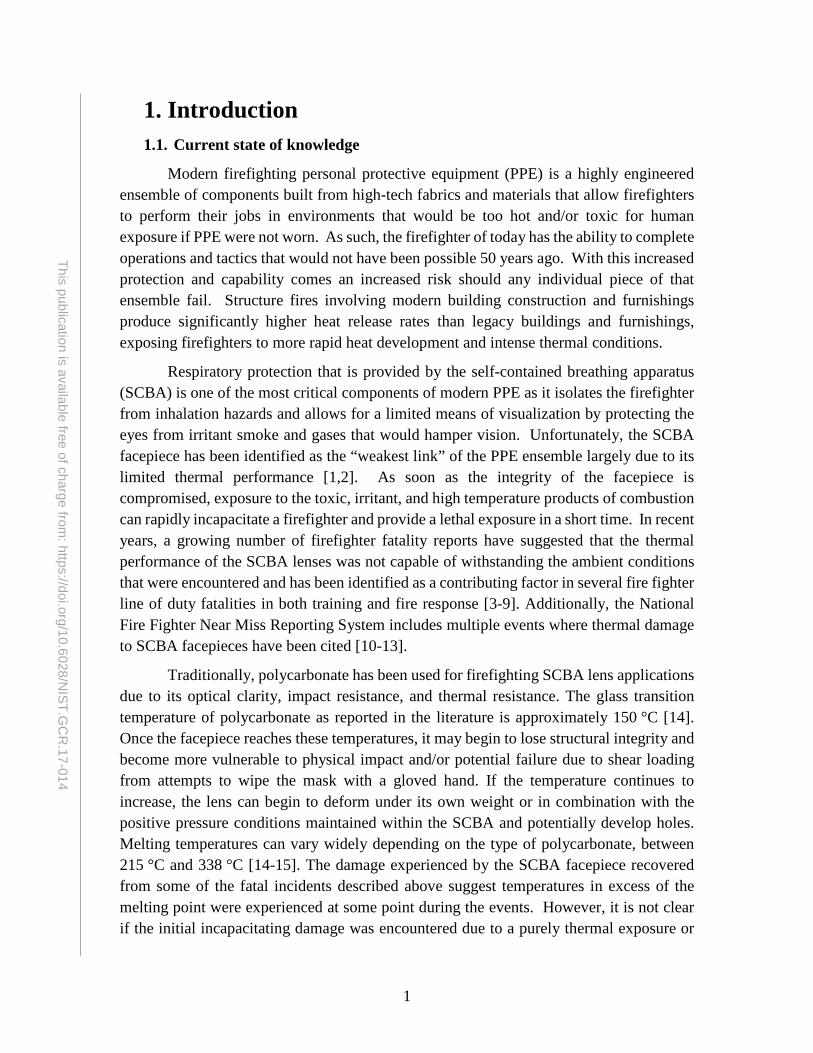
Modern firefighting personal protective equipment (PPE) is a highly engineered ensemble of components built from high-tech fabrics and materials that allow firefighters to perform their jobs in environments that would be too hot and/or toxic for human exposure if PPE were not worn. As such, the firefighter of today has the ability to complete operations and tactics that would not have been possible 50 years ago. With this increased protection and capability comes an increased risk should any individual piece of that ensemble fail. Structure fires involving modern building construction and furnishings produce significantly higher heat release rates than legacy buildings and furnishings, exposing firefighters to more rapid heat development and intense thermal conditions.
Respiratory protection that is provided by the self-contained breathing apparatus (SCBA) is one of the most critical components of modern PPE as it isolates the firefighter from inhalation hazards and allows for a limited means of visualization by protecting the eyes from irritant smoke and gases that would hamper vision. Unfortunately, the SCBA facepiece has been identified as the “weakest link” of the PPE ensemble largely due to its limited thermal performance [1,2]. As soon as the integrity of the facepiece is compromised, exposure to the toxic, irritant, and high temperature products of combustion can rapidly incapacitate a firefighter and provide a lethal exposure in a short time. In recent years, a growing number of firefighter fatality reports have suggested that the thermal performance of the SCBA lenses was not capable of withstanding the ambient conditions that were encountered and has been identified as a contributing factor in several fire fighter line of duty fatalities in both training and fire response [3-9]. Additionally, the National Fire Fighter Near Miss Reporting System includes multiple events where thermal damage to SCBA facepieces have been cited [10-13].
Traditionally, polycarbonate has been used for firefighting SCBA lens applications due to its optical clarity, impact resistance, and thermal resistance. The glass transition temperature of polycarbonate as reported in the literature is approximately 150 °C [14]. Once the facepiece reaches these temperatures, it may begin to lose structural integrity and become more vulnerable to physical impact and/or potential failure due to shear loading from attempts to wipe the mask with a gloved hand. If the temperature continues to increase, the lens can begin to deform under its own weight or in combination with the positive pressure conditions maintained within the SCBA and potentially develop holes. Melting temperatures can vary widely depending on the type of polycarbonate, between 215 °C and 338 °C [14-15]. The damage experienced by the SCBA facepiece recovered from some of the fatal incidents described above suggest temperatures in excess of the melting point were experienced at some point during the events. However, it is not clear if the initial incapacitating damage was encountered due to a purely thermal exposure or

2
This publication is available free of charge from: https://doi.org/10.6028/N
IST.GC
R.17-014
some combination of thermal and mechanical stresses or whether prior exposures may have weakened the facepiece to lower its thermal and/or mechanical capacity.
In the summer of 2010, NIST and FPRF convened a workshop to discuss the research needed to reduce the problem of heat related respirator failures during firefighting. One of the high priority items identified by all of the groups was to reassess current test methods. The workshop highlighted two research priorities: 1) “Define fire environment” and 2) “Representative and realistic testing” as a starting point for understanding conditions in which firefighters may operate that may have resulted in SCBA facepiece failures. Fireground conditions are highly variable, depending on fuel type and quantity, ventilation opening size and timing, as well as structure design, construction and interior finish, among others. Over the years, a variety of thermal environment classification systems have been developed by researchers [16-18]. Many of these systems define three or four different thermal classes based on ambient temperature and heat flux and recommend maximum exposure times for firefighters in these conditions. In 2006, Donnelly et al. [19] provide an excellent review of a multitude of reports and articles from the literature, and proposed a classification of firefighting environments into four categories with specific maximum time limits given environmental temperature and heat flux levels (Table 1). It is expected that firefighters may be exposed to Thermal Classes I and II on a fairly regular basis during normal interior fireground operations and in some cases during exterior operations where a high heat flux may be encountered from large fires or vent plumes. Class III is proposed as an upper limit for normal, but short term, fireground operations, while Class IV exposures are severe, emergency conditions to which a firefighter would not typically be exposed, but may be encountered in rapidly deteriorating situations. While this existing information provided a starting point for developing representative and realistic laboratory testing, additional study was deemed necessary focusing specifically on the SCBA facepiece.
Table 1: Recommendations for firefighter thermal classes adapted from Donnelly et al.
[19].
Thermal Class Maximum Time (min)
Maximum Temperature (oC)
Maximum Heat Flux (kW/m2)
I 25 100 1 II 15 160 2 III 2 260 10 IV <1 >260 >10
Subsequently, in a series of live-fire burn studies conducted in Bensenville, IL, Mensch et al. evaluated the thermal performance capabilities of SCBA facepieces in a series of live fire experiments conducted in fully furnished townhomes [20]. These

3
This publication is available free of charge from: https://doi.org/10.6028/N
IST.GC
R.17-014
experiments studied the facepieces in high-intensity thermal exposures involving both convective and radiative heat transfer while on a mannequin. Some of these exposures resulted in heat fluxes as high as 20 kW/m2 and 50 kW/m2, causing severe thermal degradation of the lenses. In addition to incident heat flux, exterior lens temperature was measured, which was found to be a good metric of thermal degradation of the facepieces, as physical damage to the mask was observed when the maximum exterior temperature was between 200 oC and 250 oC. These values are close to the melting temperature of polycarbonate. Additionally, exterior air temperature in the vicinity of the facepiece was monitored and it was found that facepiece damage and failure can occur even in the absence of high ambient air temperatures. Mensch et al. concluded that severe thermal conditions, such as those observed in the townhouse experiments, could precipitate rapid failure of a polycarbonate SCBA lens, but further work was needed to better quantify the threshold at which thermal damage started to occur [20].
To follow up these experiments, NIST developed a laboratory based radiant heat exposure protocol for testing SCBA facepieces [21]. Putorti et al. conducted a series of laboratory experiments, which examined the thermal performance of polycarbonate SCBA facepieces under a variety of radiant heat flux levels, with a focus on severe conditions where lens degradation and/or failure may occur on the order of 10 minutes. The mask lenses were exposed until a hole was noticed or the interior lens temperature reached a steady state. At 15 kW/m2, the most severe heat flux tested, hole formation commonly occurred in less than 4 minutes. While 15 kW/m2 exposures were determined to be a useful test criteria for SCBA lens performance in severe (Class IV) exposures, NIST researchers also found that some SCBA facepieces experienced hole formation at heat fluxes as low as 8 kW/m2, cracking at heat fluxes as low as 7 kW/m2, and bubble formation at 5 kW/m2. These bulk indications of damage would most likely require a firefighter to replace their lens due to a reduction in visual acuity. However, exposures below these levels - that may result in structural changes to the lens yet provide minimal visual indications of damage - were not studied. In their conclusions, Putorti et al. suggested that “Although much was learned about conditions associated with thermal degradation of SCBA facepiece lenses, more research and development are needed to understand the thermal degradation of facepiece lenses” [21].
Importantly, in this series of tests, thermal cracking, crazing, and bubbling occurred at approximately the same lens exterior temperature for each experiment, regardless of the incident heat flux or manufacturer of the mask. Cracking tended to occur when the exterior lens temperature reached approximately 180oC, which exceeds the glass transition temperature of polycarbonate. Likewise, hole formation typically occurred once the mask temperature reached near 270 oC, which is close to the melting temperature estimated by the authors for the type of polycarbonate in these lenses (~300oC). The study stressed that real-life SCBA facepiece degradation occurs due to a variety of factors, including radiant and convective heat transfer, mechanical damage, smoke deposition, gas and water flows,

4
This publication is available free of charge from: https://doi.org/10.6028/N
IST.GC
R.17-014
and exposure to environmental conditions. However, due to the solid agreement between the temperatures measured and facepiece damage/failure identified in these laboratory tests and the townhouse experiments, these studies provided a basis for updated testing to be incorporated in the 2013 version of NFPA 1981 Standard on Open-Circuit Self-Contained Breathing Apparatus (SCBA) for Emergency Services [22].
NFPA 1981 outlines the performance requirements for SCBA ensembles utilized by firefighting personnel. In the 2007 version, the most severe thermal test that the SCBA lens is exposed to was the Heat and Flame Resistance Test [23]. In this test, the SCBA facepiece is mounted on a headform and placed in a convection oven at 95oC for 15 minutes, while breathing is simulated at a ventilation rate of 40 L/min. After the headform is removed from the oven, the breathing rate is increased to 103 L/min and the mask is exposed to direct flame contact for 10 seconds. Immediately following the direct flame exposure, the SCBA and mannequin are dropped 150 mm. During the test, no components of the SCBA may fail or separate from the assembly, no afterflame can be sustained longer than 2.2 seconds and positive pressure must be maintained within the facepiece throughout the test. In addition, the lens cannot incur damage that obscures visual acuity below 20/100.
The Heat and Flame Resistance Test is still utilized in the 2013 version of NFPA 1981 [22]. However, based in part on the Mensch and Putorti reports, the 2013 edition includes two additional thermal tests for the SCBA facepiece: the Elevated Temperature Heat and Flame Resistance Test and the Lens Radiant Heat Test. The Elevated Heat and Flame Resistance Test requires the SCBA facepiece and breathing mannequin ensemble to be introduced into a convection oven at 260oC for 5 minutes prior to direct flame contact for 10 seconds and a vertical drop test. For the Lens Radiant Heat Test, SCBA facepieces, mounted on a headform, are exposed to a constant heat flux of 15 kW/m2 for 5 minutes. After 5 minutes of exposure, the radiant source is removed and the headform is dropped 150 mm. As part of both of these new tests, the facepiece is required to maintain a positive pressure air supply within certain limits for a total of 24 minutes. Any loss of positive pressure during the test results in a failure. These exposures represent the most aggressive Class III environment and a Class IV exposure. The current tests are well in excess of the glass transition temperatures of polycarbonate and even polyether sulfone (220˚C), another polymer finding its way into the SCBA facepiece market. While these tests provide improved confidence in the ability for SCBA to provide protection in such severe environments, such exposures are likely to cause thermal damage that would make the masks unusable for subsequent fireground operations.
However, there remains a need to study “typical” exposures to which an SCBA facepiece might be exposed hundreds of times in its service life, which might leave no indication of damage or minimal bubbling and crazing. It is likely that a fire service SCBA facepiece is commonly exposed to Class I through low-intensity-Class III environments fairly regularly and shows minimal damage as a result. However, it is not apparent how
5
This publication is available free of charge from: https://doi.org/10.6028/N
IST.GC
R.17-014
these exposures and the associated aging of the polymer lens might affect critical mechanical and thermal properties. In a recent NFPA bulletin, it is recommended that any SCBA facepiece lens found to have cracks, crazing, bubbling, deformation, discoloring, gaps or holes should be immediately removed from service and a replacement issued [2]. The assumption is that SCBA facepiece lenses showing evidence of exposure to intense heat can be used as an indication of thermal degradation and potential failure. While this recommendation is logical, there does not appear to be any scientific evidence that such indications of prior exposure are reliable indicators of changes in mechanical properties. It is possible that reduced capability may be experienced well before this damage is evident.
The need to study on-going and emerging PPE issues is well documented and lens failure issues related to improvements in respiratory protection is specifically identified as one of the top priority issues by the Tools and Equipment panel at the 2011 National Fire Service Research Agenda Symposium [24].
1.2. Goals
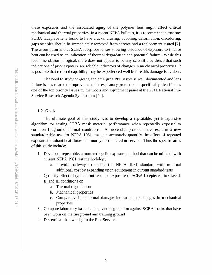
The ultimate goal of this study was to develop a repeatable, yet inexpensive algorithm for testing SCBA mask material performance when repeatedly exposed to common fireground thermal conditions. A successful protocol may result in a new standardizable test for NFPA 1981 that can accurately quantify the effect of repeated exposure to radiant heat fluxes commonly encountered in-service. Thus the specific aims of this study include:
1. Develop a repeatable, automated cyclic exposure method that can be utilized with current NFPA 1981 test methodology
a. Provide pathway to update the NFPA 1981 standard with minimal additional cost by expanding upon equipment in current standard tests
2. Quantify effect of typical, but repeated exposure of SCBA facepieces to Class I, II, and III conditions on
a. Thermal degradation b. Mechanical properties c. Compare visible thermal damage indications to changes in mechanical
properties 3. Compare laboratory based damage and degradation against SCBA masks that have
been worn on the fireground and training ground 4. Disseminate knowledge to the Fire Service

6
This publication is available free of charge from: https://doi.org/10.6028/N
IST.GC
R.17-014
2. Experimental Details 2.1. Radiant panel apparatus
Since the newly updated NFPA 1981 standard includes the Lens Radiant Heat Test, it was deemed advantageous to build a system to provide repeated exposure using the same apparatus, which would ease potential transition to standardization. Thus, the radiant panel apparatus developed by Putorti et al. [21] and utilized for the NFPA 1981 "Lens Radiant Heat Test" test (Figure 1) was modified to allow automated thermal cycling of the SCBA facepieces.
Figure 1: IFSI radiant panel apparatus based on that utilized for the NFPA 1981 "Lens
Radiant Heat Test" test [22].
The natural gas fueled radiant panel is described in ASTM E162-09 Standard Test Method for Surface Flammability of Materials Using a Radiant Energy Source. Air was entrained into the mixture using an air blower (Gast Regenair R2103) with air and gas flow rates of 16 L/min and 72 L/min, respectively. The panel is designed to provide a consistent radiant heat flux, with minimal convective heat transfer to the target. Exhaust from the panel was removed from the laboratory space using an aluminum hood and the building’s ventilation system.

7
This publication is available free of charge from: https://doi.org/10.6028/N
IST.GC
R.17-014
The SCBA facepieces were mounted on a headform that could move perpendicular to the panel on a cart to control the incident heat flux. The cart was oriented so that the front face of the SCBA lens was parallel with the face of the radiant panel. Breathing was simulated using a PosiCheck breathing machine (Honeywell Posi 3 USB) at the rate of 40 L/min. The headform assembly was attached to the PosiCheck using a 51 mm inner diameter tube. Breathing air for the experiments was provided through a compressed air cylinder cascade.
2.2. Modification for cyclic exposures
In order to allow for automated cycling of exposures, an undergraduate student team from the University of Illinois designed and constructed a water-cooled radiant heat shield mounted on a track system [25]. The proposed solution focused on the utilization of a mobile radiative shield to provide a controllable duty cycle to a test sample. Due to the extended time associated with heating up and cooling the radiant panel, thermal shielding was identified as the most effective and efficient means to deliver cyclic radiation loads to the SCBA facepiece. When engaged, the shield blocks the radiation produced by the gas-fired panel from reaching the test specimen. To disengage the shield, a microcontroller operates a motor on a rack-and-pinion drive train. The shield is cooled by water flowing through a circuitous copper pipe to prevent re-radiating heat to the test sample while the shield is engaged. To validate the effectiveness of the heat shield, several experiments were conducted under extreme conditions, with high heat fluxes for long durations.
2.2.A. Shield construction
The heat shield was constructed from two 61 cm x 61 cm plates (panel side: 1.3 cm, back side: 0.95 cm thick) of 6061 aluminum (Figure 2). Copper pipe (0.95 cm OD; 0.79 cm ID) is sandwiched between the two panels to control water flow for heat transfer. The finished channel is approximately 760 cm long and consists of 12 passes across the full width of the panels, with a 180° bend on a 5 cm diameter (Figure 3). The aluminum plates are clamped together using a five bolt compression pattern: one in each corner 8.9 cm from each side, and one bolt in the center of the plate. Both sides of the shield were coated with Rustoleum High Heat flat black spray paint (ε ≈ 0.98), which provides efficient absorption of the incident radiation. The total weight of the heat shield is approximately 205 N. Heat shield assembly drawings can be found in Appendix A and complete engineering design drawings and files are provided in supplemental materials.

8
This publication is available free of charge from: https://doi.org/10.6028/N
IST.GC
R.17-014
Figure 2: Heat shield design concept [25].
Figure 3: Heat shield interior copper waterway [25].
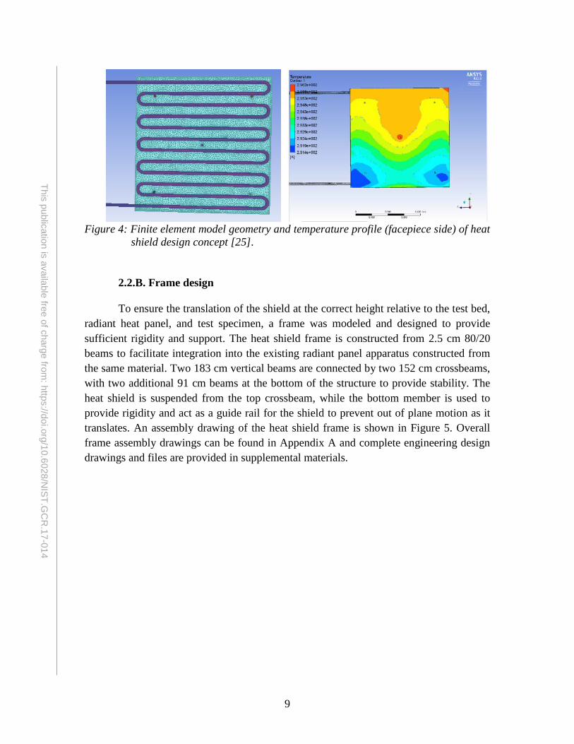
An ANSYS Fluent model was created to guide design of the heat shield assembly (Figure 4). For the initial design constraints, a constant 25 kW/m2 heat flux was assumed to emit orthogonally from the radiant heat panel to the heat shield. The entire system was contained within a 20' x 20' x 15' isothermal enclosure to simulate the walls of a testing area that were maintained at an ambient air temperature of 15 °C. A constant inlet mass flow rate of 17 °C water at 0.16 kg/s was utilized to simulate the water supply used during testing. With the selected materials, the maximum steady state temperature reached on the side of the heat shield closest to the test specimen was approximately 23 °C. Assuming a worst case scenario where all of the thermal energy from the back of the panel was directed towards the facepiece, the maximum off-cycle heat flux to the sample would be 45 W/m2, or approximately 0.2% of the incident heat flux from the radiant heat panel. In addition, this model calculated the outlet water temperature to be 22 °C.
9
This publication is available free of charge from: https://doi.org/10.6028/N
IST.GC
R.17-014
Figure 4: Finite element model geometry and temperature profile (facepiece side) of heat
shield design concept [25].
2.2.B. Frame design
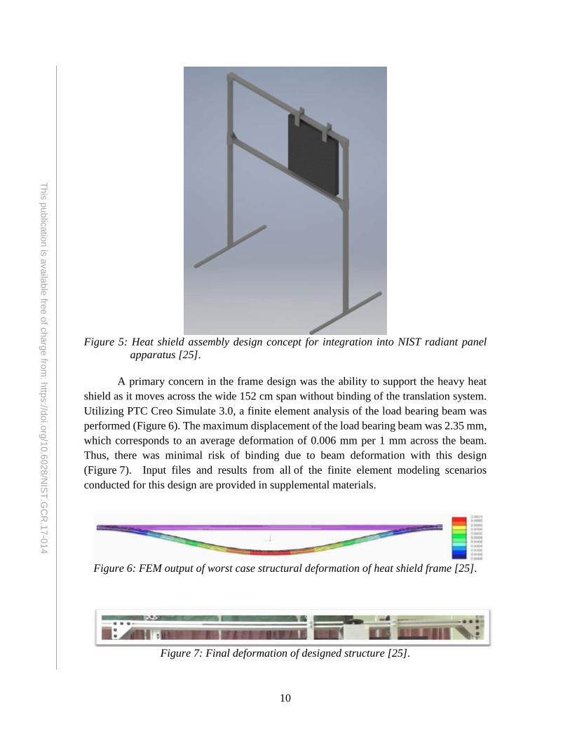
To ensure the translation of the shield at the correct height relative to the test bed, radiant heat panel, and test specimen, a frame was modeled and designed to provide sufficient rigidity and support. The heat shield frame is constructed from 2.5 cm 80/20 beams to facilitate integration into the existing radiant panel apparatus constructed from the same material. Two 183 cm vertical beams are connected by two 152 cm crossbeams, with two additional 91 cm beams at the bottom of the structure to provide stability. The heat shield is suspended from the top crossbeam, while the bottom member is used to provide rigidity and act as a guide rail for the shield to prevent out of plane motion as it translates. An assembly drawing of the heat shield frame is shown in Figure 5. Overall frame assembly drawings can be found in Appendix A and complete engineering design drawings and files are provided in supplemental materials.
10
This publication is available free of charge from: https://doi.org/10.6028/N
IST.GC
R.17-014
Figure 5: Heat shield assembly design concept for integration into NIST radiant panel
apparatus [25].
A primary concern in the frame design was the ability to support the heavy heat shield as it moves across the wide 152 cm span without binding of the translation system. Utilizing PTC Creo Simulate 3.0, a finite element analysis of the load bearing beam was performed (Figure 6). The maximum displacement of the load bearing beam was 2.35 mm, which corresponds to an average deformation of 0.006 mm per 1 mm across the beam. Thus, there was minimal risk of binding due to beam deformation with this design (Figure 7). Input files and results from all of the finite element modeling scenarios conducted for this design are provided in supplemental materials.
Figure 6: FEM output of worst case structural deformation of heat shield frame [25].
Figure 7: Final deformation of designed structure [25].
11
This publication is available free of charge from: https://doi.org/10.6028/N
IST.GC
R.17-014
2.2.C. Translation
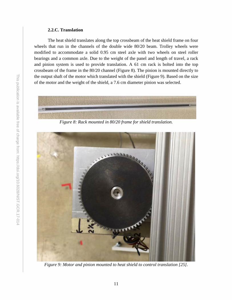
The heat shield translates along the top crossbeam of the heat shield frame on four wheels that run in the channels of the double wide 80/20 beam. Trolley wheels were modified to accommodate a solid 0.95 cm steel axle with two wheels on steel roller bearings and a common axle. Due to the weight of the panel and length of travel, a rack and pinion system is used to provide translation. A 61 cm rack is bolted into the top crossbeam of the frame in the 80/20 channel (Figure 8). The pinion is mounted directly to the output shaft of the motor which translated with the shield (Figure 9). Based on the size of the motor and the weight of the shield, a 7.6 cm diameter pinion was selected.
Figure 8: Rack mounted in 80/20 frame for shield translation.
Figure 9: Motor and pinion mounted to heat shield to control translation [25].

12
This publication is available free of charge from: https://doi.org/10.6028/N
IST.GC
R.17-014
The stepper motor (HT24-106, Applied Motion Products) was sized based on the force required to overcome static friction in moving the panel (~27 N), with a safety factor of over 2.5 to ensure reliable translation. The motion of the heat shield is controlled by a commercially available microcontroller (Uno Rev, Arduino with an Adafruit Stepper Motor Shield v2.3). The code that governs the motion requires four user inputs: on-cycle time, off-cycle time, translation time, and number of cycles. After the specified number of cycles has been completed, the shield defaults to the closed position, shielding the test specimen from incident radiation. The microcontroller code used for programmable, automated translation is included in Appendix B.
2.2.D. System design and validation Final engineering drawings of the modified radiant panel apparatus are provided in
supplemental documentation, with assembly drawings and reference dimensions provided in Appendix A. Figure 10 shows images of the final test set up. The 80/20 heat shield frame interfaces seamlessly with the existing test bed and the shield is free to translate between the open and closed positions.
Figure 10: Heat shield and frame integrated into the existing radiant panel apparatus.
Figure 11 provides a series of IR images that show the heat shield as it translates from the closed to the open position from the perspective of the SCBA facepiece. With the heat shield in the closed position, the average back side temperature is approximately 18 °C, even with the radiant panel at full operating temperature. With the shield translated to the fully open position, there is no disruption in the thermal exposures from the original design.
13
This publication is available free of charge from: https://doi.org/10.6028/N
IST.GC
R.17-014
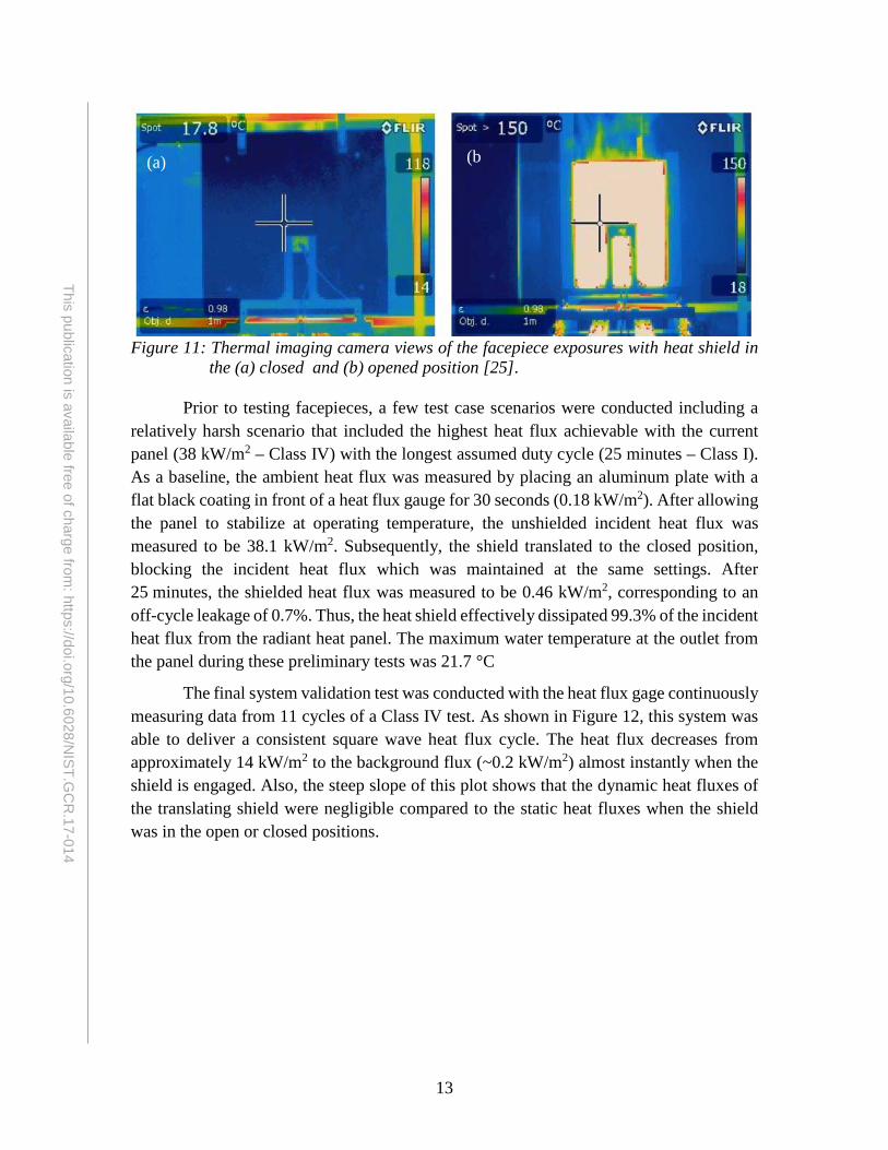
Figure 11: Thermal imaging camera views of the facepiece exposures with heat shield in
the (a) closed and (b) opened position [25].
Prior to testing facepieces, a few test case scenarios were conducted including a relatively harsh scenario that included the highest heat flux achievable with the current panel (38 kW/m2 – Class IV) with the longest assumed duty cycle (25 minutes – Class I). As a baseline, the ambient heat flux was measured by placing an aluminum plate with a flat black coating in front of a heat flux gauge for 30 seconds (0.18 kW/m2). After allowing the panel to stabilize at operating temperature, the unshielded incident heat flux was measured to be 38.1 kW/m2. Subsequently, the shield translated to the closed position, blocking the incident heat flux which was maintained at the same settings. After 25 minutes, the shielded heat flux was measured to be 0.46 kW/m2, corresponding to an off-cycle leakage of 0.7%. Thus, the heat shield effectively dissipated 99.3% of the incident heat flux from the radiant heat panel. The maximum water temperature at the outlet from the panel during these preliminary tests was 21.7 °C
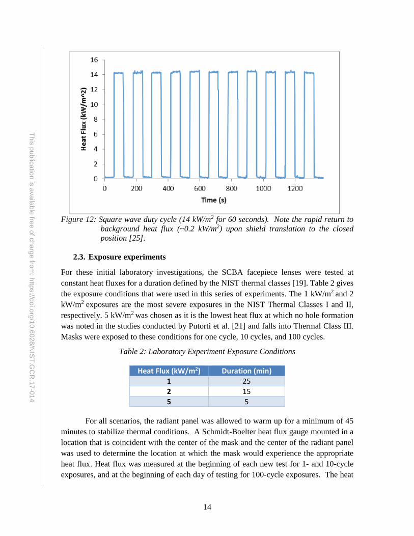
The final system validation test was conducted with the heat flux gage continuously measuring data from 11 cycles of a Class IV test. As shown in Figure 12, this system was able to deliver a consistent square wave heat flux cycle. The heat flux decreases from approximately 14 kW/m2 to the background flux (~0.2 kW/m2) almost instantly when the shield is engaged. Also, the steep slope of this plot shows that the dynamic heat fluxes of the translating shield were negligible compared to the static heat fluxes when the shield was in the open or closed positions.
(a) (b
14
This publication is available free of charge from: https://doi.org/10.6028/N
IST.GC
R.17-014
Figure 12: Square wave duty cycle (14 kW/m2 for 60 seconds). Note the rapid return to
background heat flux (~0.2 kW/m2) upon shield translation to the closed position [25].
2.3. Exposure experiments
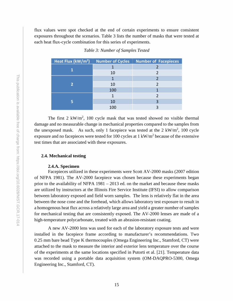
For these initial laboratory investigations, the SCBA facepiece lenses were tested at constant heat fluxes for a duration defined by the NIST thermal classes [19]. Table 2 gives the exposure conditions that were used in this series of experiments. The 1 kW/m2 and 2 kW/m2 exposures are the most severe exposures in the NIST Thermal Classes I and II, respectively. 5 kW/m2 was chosen as it is the lowest heat flux at which no hole formation was noted in the studies conducted by Putorti et al. [21] and falls into Thermal Class III. Masks were exposed to these conditions for one cycle, 10 cycles, and 100 cycles.
Table 2: Laboratory Experiment Exposure Conditions
Heat Flux (kW/m2) Duration (min) 1 25 2 15 5 5
For all scenarios, the radiant panel was allowed to warm up for a minimum of 45 minutes to stabilize thermal conditions. A Schmidt-Boelter heat flux gauge mounted in a location that is coincident with the center of the mask and the center of the radiant panel was used to determine the location at which the mask would experience the appropriate heat flux. Heat flux was measured at the beginning of each new test for 1- and 10-cycle exposures, and at the beginning of each day of testing for 100-cycle exposures. The heat
15
This publication is available free of charge from: https://doi.org/10.6028/N
IST.GC
R.17-014
flux values were spot checked at the end of certain experiments to ensure consistent exposures throughout the scenarios. Table 3 lists the number of masks that were tested at each heat flux-cycle combination for this series of experiments.
Table 3: Number of Samples Tested
Heat Flux (kW/m2) Number of Cycles Number of Facepieces
1 1 2 10 2
2 1 2
10 2 100 1
5 1 2
10 3 100 3
The first 2 kW/m2, 100 cycle mask that was tested showed no visible thermal damage and no measurable change in mechanical properties compared to the samples from the unexposed mask. As such, only 1 facepiece was tested at the 2 kW/m2, 100 cycle exposure and no facepieces were tested for 100 cycles at 1 kW/m2 because of the extensive test times that are associated with these exposures.
2.4. Mechanical testing
2.4.A. Specimen Facepieces utilized in these experiments were Scott AV-2000 masks (2007 edition
of NFPA 1981). The AV-2000 facepiece was chosen because these experiments began prior to the availability of NFPA 1981 – 2013 ed. on the market and because these masks are utilized by instructors at the Illinois Fire Service Institute (IFSI) to allow comparison between laboratory exposed and field worn samples. The lens is relatively flat in the area between the nose cone and the forehead, which allows laboratory test exposure to result in a homogenous heat flux across a relatively large area and yield a greater number of samples for mechanical testing that are consistently exposed. The AV-2000 lenses are made of a high-temperature polycarbonate, treated with an abrasion-resistant coating.
A new AV-2000 lens was used for each of the laboratory exposure tests and were installed in the facepiece frame according to manufacturer’s recommendations. Two 0.25 mm bare bead Type K thermocouples (Omega Engineering Inc., Stamford, CT) were attached to the mask to measure the interior and exterior lens temperature over the course of the experiments at the same locations specified in Putorti et al. [21]. Temperature data was recorded using a portable data acquisition system (OM-DAQPRO-5300, Omega Engineering Inc., Stamford, CT).

16
This publication is available free of charge from: https://doi.org/10.6028/N
IST.GC
R.17-014
In addition to the laboratory exposed facepieces, a series of field worn masks were also tested. The heat exposure history for these masks cannot be accurately quantified, but they serve as an important benchmark with which to compare the lab results. These masks were obtained from instructors working live-fire training classes at the Illinois Fire Service Institute.
2.4.B. Specimen harvesting Due to the nonplanar nature of the SCBA facepieces, conducting ASTM standard
mechanical property evaluation from lenses exposed to realistic conditions is challenging. The existing designs limit the specimen length that can be tested and the curvature presents challenges to both the exposure of the lens and machining techniques that are available. Several methods for harvesting samples from the central region of the facepiece lens were developed and tested. Ultimately, an approach that began with an original rough cut to rectangular dimensions followed by a finished guided mill process was selected. For the tensile test samples, five sections were harvested from each lens, in the configuration shown in Figure 13a, labeled A through E (from left to right). Only one sample could be extracted from the center of each mask for impact testing, Figure 13b. AV-2000 facepieces have a raised notch in the forehead area, which is used to fasten the lens to the frame of the mask. To facilitate fixturing of samples, this notch was carefully filed down so that the grip/clamp area was unimpeded. This section of the mask was outside of the test area and did not affect mechanical testing results.
Figure 13: Mechanical test sample harvesting locations: (a) tensile test, and (b) impact test
(a) (b)
17
This publication is available free of charge from: https://doi.org/10.6028/N
IST.GC
R.17-014
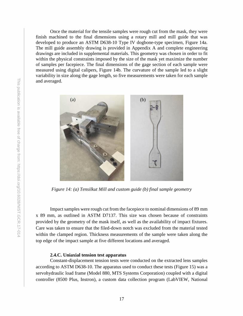
Once the material for the tensile samples were rough cut from the mask, they were finish machined to the final dimensions using a rotary mill and mill guide that was developed to produce an ASTM D638-10 Type IV dogbone-type specimen, Figure 14a. The mill guide assembly drawing is provided in Appendix A and complete engineering drawings are included in supplemental materials. This geometry was chosen in order to fit within the physical constraints imposed by the size of the mask yet maximize the number of samples per facepiece. The final dimensions of the gage section of each sample were measured using digital calipers, Figure 14b. The curvature of the sample led to a slight variability in size along the gage length, so five measurements were taken for each sample and averaged.
Figure 14: (a) Tensilkut Mill and custom guide (b) final sample geometry
Impact samples were rough cut from the facepiece to nominal dimensions of 89 mm x 89 mm, as outlined in ASTM D7137. This size was chosen because of constraints provided by the geometry of the mask itself, as well as the availability of impact fixtures. Care was taken to ensure that the filed-down notch was excluded from the material tested within the clamped region. Thickness measurements of the sample were taken along the top edge of the impact sample at five different locations and averaged.
2.4.C. Uniaxial tension test apparatus Constant-displacement tension tests were conducted on the extracted lens samples
according to ASTM D638-10. The apparatus used to conduct these tests (Figure 15) was a servohydraulic load frame (Model 880, MTS Systems Corporation) coupled with a digital controller (8500 Plus, Instron), a custom data collection program (LabVIEW, National
(a) (b)

18
This publication is available free of charge from: https://doi.org/10.6028/N
IST.GC
R.17-014
Instruments) and a 2.2 kN load cell (Lebow 3173-500, Eaton Corporation). Strain data was recorded for certain samples through the elastic region using a 25 mm gage length extensometer with 10% maximum range (Model 380041-01, MTS Systems Corporation). The data from these tests was used to characterize the tensile strength, Young’s Modulus and estimated strain to failure for each tensile sample.
Figure 15: Servohydraulic quasistatic tensile test apparatus.
Values of engineering stress and strain are computed from original cross sectional area and the change in the 25 mm gage length. Tensile strength is defined as the peak stress that is experienced by the sample during the uniaxial experiment. Mechanical properties of polycarbonate materials vary widely due to the many different variations in chemistry and grades available. However, the most common values found in engineering handbooks for tensile strength are typically between 60 MPa and 75 MPa [e.g. summarized in 25]. In these experiments, strain is computed with respect to the 25.4 mm gage section of the lens samples and extensometer. Young’s modulus - also referred to as the modulus of elasticity - is a measure of the stiffness of a material and is found by calculating the slope of the stress-strain curve in the elastic region of a sample. This value was calculated for the subgroup of facepiece samples that were tested using the extensometer. The Elastic Modulus is a material constant, with typical values ranging from 2.0 GPa to 2.4 GPa for polycarbonate [e.g. 26, 27].

19
This publication is available free of charge from: https://doi.org/10.6028/N
IST.GC
R.17-014
Changes in sample ductility is of particular interest in these experiments and is quantified as the strain to failure (strain value at point where the lens sample fractures). Due to the large deformation of many of these samples (>100%), electromechanical extensometry was not a viable option. So, an estimated value is computed based on the displacement of the grips, normalized to the 25.4 mm gage length of the tensile testing specimens. This approach for estimating ductility introduces some important errors, such as slippage in the grips of the load frame. Nevertheless, it gives a useful approximation to the ductility of the samples and allow comparison between exposures in a consistent manner. Once the sample begins to neck (at approximately 6-8% strain), the deformation is contained within the gage length as the neck grows until it reaches the shoulders of the sample. Handbook values of strain to failure for polycarbonate are often reported between 110 and 150 % [e.g. 25].
2.4.D. Impact test apparatus Impact testing was performed on the facepiece lens samples in accordance with
ASTM D5629-10. These tests were conducted using an impact load frame (Dynatup Model 8210, Instron Corporation) with a 15.9 mm instrumented tup (Figure 16). The drop tower utilized a pneumatic clamp with a 76 mm diameter fixture. Impact tests were conducted to compare five unexposed SCBA lens samples to five field worn samples that display various degrees of damage.
The total fracture energy of the lens samples is calculated by integrating the force recorded by the load cell with respect to displacement of the tup. Since the lens specimens are not instrumented to record the deflection of the material during impact, the displacement is computed mathematically by evaluating the motion of the tup. This motion is a function of the force recorded by the load cell (P(t)), the mass of the impactor (M), the velocity of the tup when it impacts the sample(v0) and the time (t) with respect to the initiation of impact. The displacement is found by integrating the expression for velocity with respect to time
𝑣𝑣(𝑡𝑡) = 𝑣𝑣0 + ∫ �𝑔𝑔 − 𝑃𝑃(𝑡𝑡)𝑀𝑀�𝑡𝑡
0 (1)
𝑥𝑥(𝑡𝑡) = ∫ 𝑣𝑣(𝑡𝑡)𝑑𝑑𝑡𝑡𝑡𝑡0 (2)
The numerical integration to determine the position (x) of the tup is performed by the LabVIEW software. The fracture energy (E) is determined by:
𝐸𝐸 = ∫𝑃𝑃𝑑𝑑𝑥𝑥 (3)
Large fracture energies and significant post-impact deformation are indicative of ductile mechanical behavior, whereas lower fracture energies and sample failure with multiple pieces or with sharp fracture patterns indicate brittle response.

20
This publication is available free of charge from: https://doi.org/10.6028/N
IST.GC
R.17-014
Figure 16: Impact testing apparatus.
2.4. Statistics
Statistically significant differences in material properties were determined using a student’s t-test. The distribution of mechanical properties determined by samples harvested from the laboratory-exposed and field-exposed samples are compared to the baseline unexposed samples. Differences in mechanical results were determined to be significant when the p-value is less than 0.05.

21
This publication is available free of charge from: https://doi.org/10.6028/N
IST.GC
R.17-014
3. Results and Discussion 3.1. Facepiece temperatures during repeated radiant exposures
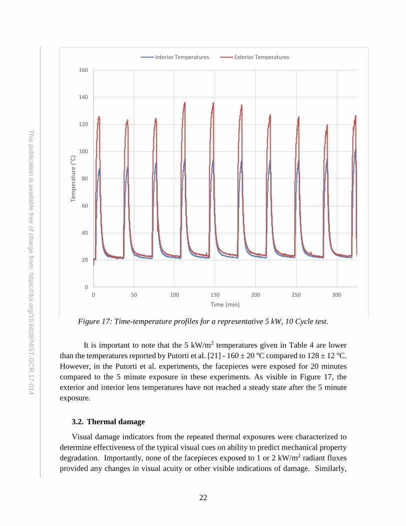
The average exterior and interior lens temperatures during the 10 cycle 1, 2, and 5 kW/m2 laboratory exposure cycles are summarized in Table 4. All of these temperatures are well below glass transition temperature for polycarbonate, such that concerns with viscoelastic deformation and creep are minimal. The mild Class I condition resulted in slight increase from ambient conditions. For reference, the typical laboratory conditions were held at approximately 22 oC, though temperatures reached as high as 27 oC during some tests. As expected, some fluctuation of maximum temperatures achieved during each exposure cycle is noted throughout the tests (e.g. Figure 17). These fluctuations are due to a combination of environmental and procedural factors. In addition to the ambient temperature changes in the lab, air drafts caused by doors opening and closing as personnel moved through the lab, can result in localized variations in the facepiece exposures. At the 5 kW/m2 heat flux level, the mask itself can deform slightly with the pressure changes during breathing, which can impact thermocouple contact with the surface as well as slight changes in placement during each cycle. The coefficient of variation (standard deviation divided by mean value) in Table 4 was always less than 10%, which is similar to the exterior temperature variations reported for the 5 kW/m2 tests by Purtorti et al. [21] (160 ± 20 oC, or 12.5%).
Table 4: 10 cycle Lens Maximum Temperatures (Mean ± Standard Deviation) Heat Flux (kW/m2) Exterior Temperature (oC) Interior Temperature (oC)
1 37.7 ± 0.5 35.6 ± 0.4 2 59.6 ± 5.7 45.6 ± 1.9 5 127.8 ± 12.4 93.2 ± 4.1
Thermocouple placement was found to have a significant impact on the measured temperatures. As the lens exposure is due to radiation from the gas-fired panel, the thermocouple wire itself can locally block the energy source. The lens thermocouple was oriented so that the bead and wire were approximately perpendicular to the surface of the lens. This likely resulted in a measured lens temperature that was lower than the temperature of the surrounding lens material. Polycarbonate is a poor conductor, so sharp gradients in temperatures can be present around the thermocouples. Thus, slight differences in the angle of the wire and orientation of the bead can impact the local temperatures measured, without affecting the bulk exposure. In fact, highly localized changes in thermal damage to the mask can be seen in the vicinity of the thermocouple wire. In early tests, attempts were made to utilize tape to assist keeping the thermocouple in place, but this resulted in significant (though localized to the taped area) changes to the damage patterns that resulted. Future work should attempt to better quantify the effect of thermocouple position and accurately measure the lens temperature without obstructing the incident heat flux.
22
This publication is available free of charge from: https://doi.org/10.6028/N
IST.GC
R.17-014
Figure 17: Time-temperature profiles for a representative 5 kW, 10 Cycle test.
It is important to note that the 5 kW/m2 temperatures given in Table 4 are lower than the temperatures reported by Putorti et al. [21] - 160 ± 20 oC compared to 128 ± 12 oC. However, in the Putorti et al. experiments, the facepieces were exposed for 20 minutes compared to the 5 minute exposure in these experiments. As visible in Figure 17, the exterior and interior lens temperatures have not reached a steady state after the 5 minute exposure.
3.2. Thermal damage
Visual damage indicators from the repeated thermal exposures were characterized to determine effectiveness of the typical visual cues on ability to predict mechanical property degradation. Importantly, none of the facepieces exposed to 1 or 2 kW/m2 radiant fluxes provided any changes in visual acuity or other visible indications of damage. Similarly,
0
20
40
60
80
100
120
140
160
0 50 100 150 200 250 300
Tem
pera
ture
(°C)
Time (min)
Interior Temperatures Exterior Temperatures
23
This publication is available free of charge from: https://doi.org/10.6028/N
IST.GC
R.17-014
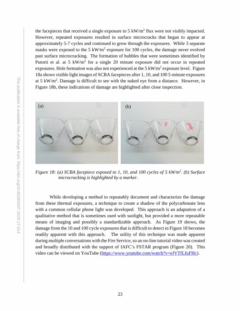
the facepieces that received a single exposure to 5 kW/m2 flux were not visibly impacted. However, repeated exposures resulted in surface microcracks that began to appear at approximately 5-7 cycles and continued to grow through the exposures. While 3 separate masks were exposed to the 5 kW/m2 exposure for 100 cycles, the damage never evolved past surface microcracking. The formation of bubbles that were sometimes identified by Putorti et al. at 5 kW/m2 for a single 20 minute exposure did not occur in repeated exposures. Hole formation was also not experienced at the 5 kW/m2 exposure level. Figure 18a shows visible light images of SCBA facepieces after 1, 10, and 100 5-minute exposures at 5 kW/m2. Damage is difficult to see with the naked eye from a distance. However, in Figure 18b, these indications of damage are highlighted after close inspection.
Figure 18: (a) SCBA facepiece exposed to 1, 10, and 100 cycles of 5 kW/m2. (b) Surface
microcracking is highlighted by a marker.
While developing a method to repeatably document and characterize the damage from these thermal exposures, a technique to create a shadow of the polycarbonate lens with a common cellular phone light was developed. This approach is an adaptation of a qualitative method that is sometimes used with sunlight, but provided a more repeatable means of imaging and possibly a standardizable approach. As Figure 19 shows, the damage from the 10 and 100 cycle exposures that is difficult to detect in Figure 18 becomes readily apparent with this approach. The utility of this technique was made apparent during multiple conversations with the Fire Service, so an on-line tutorial video was created and broadly distributed with the support of IAFC’s FSTAR program (Figure 20). This video can be viewed on YouTube (https://www.youtube.com/watch?v=eJVTfLfuFHc).
(a) (b)

24
This publication is available free of charge from: https://doi.org/10.6028/N
IST.GC
R.17-014
Figure 19: The same SCBA facepiece exposed to 1, 10, and 100 cycles of 5 kW/m2, but
imaged with a soft, broad illumination from a cell phone light, projecting a shadow of the damage on to a uniform, planar background.
Figure 20. Screenshots from SCBA Inspection video produced and distributed to the Fire Service.
It is important to note that the damage produced by the laboratory exposures is
expected to be slightly different than that accumulated in field worn lenses. Exposures in the field are likely to be varied in terms of the orientation of the mask to the radiant source as a firefighter completes their tasks. In the lab, the facepiece exposure is relatively consistent for each scenario, where the front of the lens will repeatably be closer to the radiant panel than the outer sections which curve away from the panel. To quantify the effect of the mask’s curvature on reduction in thermal exposure, a test was conducted to evaluate the variation in heat flux that accompanies small changes in distance from the panel. The heat flux gauge was placed at the nominal 5 kW/m2 position and data recorded

25
This publication is available free of charge from: https://doi.org/10.6028/N
IST.GC
R.17-014
for 5 minutes. The gauge was then moved away from the radiant panel by 12.5 mm and 25 mm, and then moved towards the panel from the 5 kW/m2 mark by 12.5 mm and 25 mm. Heat flux data was recorded at each location for five minutes (Figure 21). It can be seen that moving the cart 25 mm in either direction increases or decreases the heat flux by 0.5 kW/m2. For a change in position of 12.5 mm, which is similar to the magnitude of the curvature effect, the impact on heat flux is approximately 0.25 kW/m2. Thus, the outside samples (A, E) are being exposed to a ~5% lower heat flux than the center samples (B-D). While this variation is relatively small due to the curvature effect, the thermal damage developed in the lenses is significantly concentrated on the front section of the facepiece (Figure 19). This may suggest that exposures to the 5 kW/m2 level provides a critical level for damage accumulation to occur.
Figure 21: Relative impact of distance from the radiant panel on heat flux for approximate
5 kW/m2 condition. Labels indicate mean ± standard deviation (kW/m2) for data collected at 1 Hz.
0
1
2
3
4
5
6
7
0 200 400 600 800 1000 1200 1400 1600
Heat
Flu
x (k
W/m
2)
Time (s)
5.63 ± 0.10
5.25 ± 0.09
4.58 ± 0.064.78 ± 0.08
5.07 ± 0.07
26
This publication is available free of charge from: https://doi.org/10.6028/N
IST.GC
R.17-014
3.3. Quasistatic uniaxial tensile test results
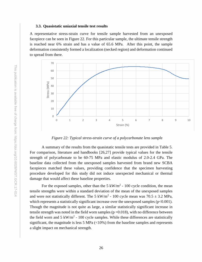
A representative stress-strain curve for tensile sample harvested from an unexposed facepiece can be seen in Figure 22. For this particular sample, the ultimate tensile strength is reached near 6% strain and has a value of 65.6 MPa. After this point, the sample deformation consistently formed a localization (necked region) and deformation continued to spread from there.
Figure 22: Typical stress-strain curve of a polycarbonate lens sample
A summary of the results from the quasistatic tensile tests are provided in Table 5. For comparison, literature and handbooks [26,27] provide typical values for the tensile strength of polycarbonate to be 60-75 MPa and elastic modulus of 2.0-2.4 GPa. The baseline data collected from the unexposed samples harvested from brand new SCBA facepieces matched these values, providing confidence that the specimen harvesting procedure developed for this study did not induce unexpected mechanical or thermal damage that would affect these baseline properties.
For the exposed samples, other than the 5 kW/m2 - 100 cycle condition, the mean tensile strengths were within a standard deviation of the mean of the unexposed samples and were not statistically different. The 5 kW/m2 - 100 cycle mean was 70.5 ± 3.2 MPa, which represents a statistically significant increase over the unexposed samples (p<0.001). Though the magnitude is not quite as large, a similar statistically significant increase in tensile strength was noted in the field worn samples (p =0.018), with no difference between the field worn and 5 kW/m2 - 100 cycle samples. While these differences are statistically significant, the magnitude is less 5 MPa (<10%) from the baseline samples and represents a slight impact on mechanical strength.
0
10
20
30
40
50
60
70
0 1 2 3 4 5 6 7 8 9 10
Stre
ss (M
Pa)
Strain (%)

27
This publication is available free of charge from: https://doi.org/10.6028/N
IST.GC
R.17-014
Table 5: Tensile test results (mean ± standard deviation). Heat Flux
(kW/m2) Cycles No. of Samples Tensile Strength
(MPa) Elastic
Modulus (GPa) Strain to Failure
(mm/mm)
Unexposed 13 65.8 ± 1.9 2.21 ± 0.12 1.37 ± 0.15
1 1 10 67.5 ± 2.0 2.22 ± 0.05 1.42 ± 0.07 10 10 66.2 ± 1.6 2.20 ± 0.10 1.43 ± 0.10
2 1 10 65.7 ± 1.4 2.21 ± 0.07 1.38 ± 0.14
10 10 66.1 ± 0.9 2.22 ± 0.11 1.31 ± 0.28 100 5 65.3 ± 0.6 2.15 ± 0.06 1.42 ± 0.09
5 1 10 64.9 ± 1.4 2.21 ± 0.11 1.39 ± 0.07
10 15 66.12± 1.8 2.20 ± 0.10 1.26 ± 0.25 100 15 70.5 ± 3.21* 2.19 ± 0.15 0.77 ± 0.44*
Field Worn 20 68.0 ± 0.7* 2.33 ± 0.20 0.24 ± 0.12* * indicates a statistically significant difference compared to Unexposed sample (p<0.05).
The exposed sample elastic modulus values were likewise similar to the baseline unexposed material for nearly all of the exposure conditions. The field worn samples exhibited a slightly higher mean value of 2.33 GPa ± 0.20 GPa. While this difference was not found to be statistically significant, it is possible that some field worn SCBA lenses have a higher elastic modulus than unexposed or lightly exposed samples due to effects not encountered in the laboratory exposure (e.g. UV degradation). Further study of these potential effects is needed.
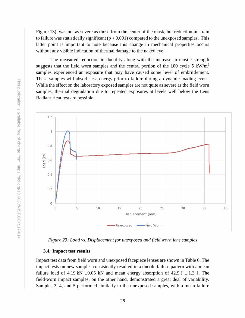
The most interesting change in mechanical properties was found in the change in ductility of these samples. To help visualize this effect, Figure 23 shows the load versus displacement for representative field worn and unexposed samples, demonstrating significant differences in ductility. With the exception of the 5 kW/m2 - 100-cycle tests, the strain to failure achieved by the exposed lens samples were similar to the unexposed material (~1.4 mm/mm or 140%). Again, these data were consistent with values from literature, which list typical strain to failure values as 1.1-1.5 (110-150%). Field worn samples, with an estimated strain to failure of 0.24 ± 0.12, had the largest reduction in ductility compared to the unexposed samples (p < 0.001). On average, the 5kW/m2 – 100 cycle samples also demonstrated a significantly reduced (p < 0.001) strain to failure (0.77 ± 0.44). This effect was most pronounced in the samples that were harvested from the center of the facepiece lens. In fact, the data from these samples followed a strongly bi-modal distribution with clustered data from samples taken nearest to the heat source compared to those farther away from the radiant panel. Separating this data set in to two subgroups results in strain to failure of 0.36±0.11 and 1.13±0.27 respectively. The change in properties of the heavily exposed 5 kW/m2, 100 cycle samples is similar to the field worn samples, though the loss of ductility was quite as severe. The impact of this extended exposure on the samples collected from the sides of the lenses (e.g. positions A and E in
28
This publication is available free of charge from: https://doi.org/10.6028/N
IST.GC
R.17-014
Figure 13) was not as severe as those from the center of the mask, but reduction in strain to failure was statistically significant (p < 0.001) compared to the unexposed samples. This latter point is important to note because this change in mechanical properties occurs without any visible indication of thermal damage to the naked eye.
The measured reduction in ductility along with the increase in tensile strength suggests that the field worn samples and the central portion of the 100 cycle 5 kW/m2 samples experienced an exposure that may have caused some level of embrittlement. These samples will absorb less energy prior to failure during a dynamic loading event. While the effect on the laboratory exposed samples are not quite as severe as the field worn samples, thermal degradation due to repeated exposures at levels well below the Lens Radiant Heat test are possible.
Figure 23: Load vs. Displacement for unexposed and field worn lens samples
3.4. Impact test results
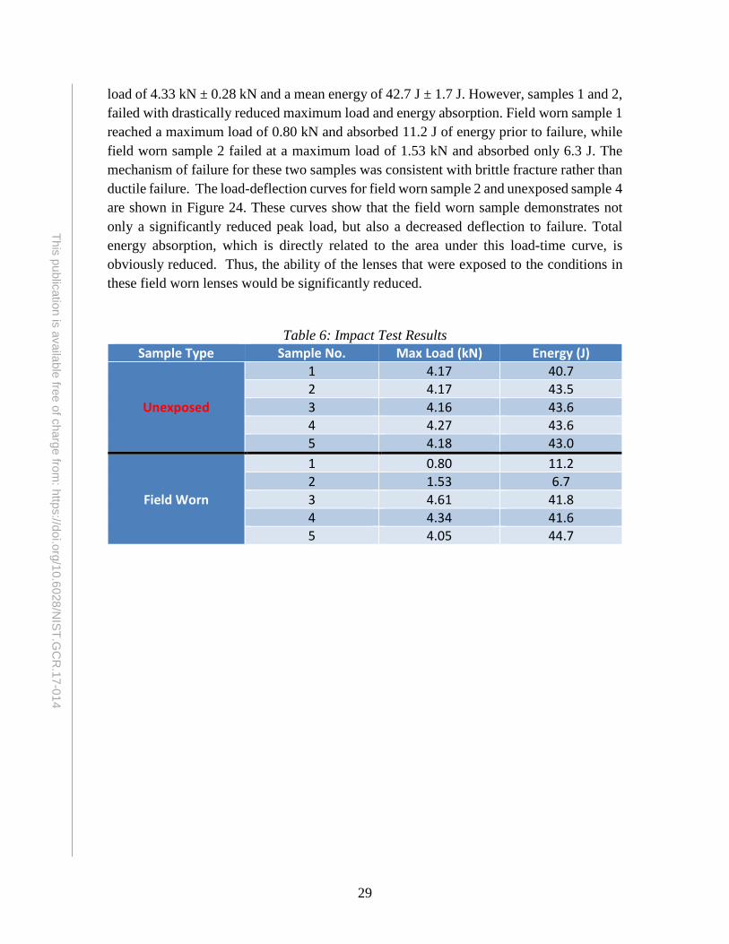
Impact test data from field worn and unexposed facepiece lenses are shown in Table 6. The impact tests on new samples consistently resulted in a ductile failure pattern with a mean failure load of 4.19 kN ±0.05 kN and mean energy absorption of 42.9 J ±.1.3 J. The field-worn impact samples, on the other hand, demonstrated a great deal of variability. Samples 3, 4, and 5 performed similarly to the unexposed samples, with a mean failure
0
0.2
0.4
0.6
0.8
1
1.2
0 5 10 15 20 25 30 35 40
Load
(kN
)
Displacement (mm)
Unexposed Field Worn
29
This publication is available free of charge from: https://doi.org/10.6028/N
IST.GC
R.17-014
load of 4.33 kN ± 0.28 kN and a mean energy of 42.7 J ± 1.7 J. However, samples 1 and 2, failed with drastically reduced maximum load and energy absorption. Field worn sample 1 reached a maximum load of 0.80 kN and absorbed 11.2 J of energy prior to failure, while field worn sample 2 failed at a maximum load of 1.53 kN and absorbed only 6.3 J. The mechanism of failure for these two samples was consistent with brittle fracture rather than ductile failure. The load-deflection curves for field worn sample 2 and unexposed sample 4 are shown in Figure 24. These curves show that the field worn sample demonstrates not only a significantly reduced peak load, but also a decreased deflection to failure. Total energy absorption, which is directly related to the area under this load-time curve, is obviously reduced. Thus, the ability of the lenses that were exposed to the conditions in these field worn lenses would be significantly reduced.
Table 6: Impact Test Results Sample Type Sample No. Max Load (kN) Energy (J)
Unexposed
1 4.17 40.7 2 4.17 43.5 3 4.16 43.6 4 4.27 43.6 5 4.18 43.0
Field Worn
1 0.80 11.2 2 1.53 6.7 3 4.61 41.8 4 4.34 41.6 5 4.05 44.7

30
This publication is available free of charge from: https://doi.org/10.6028/N
IST.GC
R.17-014
Figure 24: Typical load vs. deflection curves for impact tested samples.
The variation in impact properties among the field worn samples may not be surprising, since the history of thermal exposures to these lenses cannot be accurately quantified. Qualitatively, the lenses that performed similarly to the unexposed samples had less visible thermal damage than those exhibiting decreased properties. Field samples 3-5 had minor surface cracking and abrasions, whereas samples 1 and 2 had subsurface cracking and severe crazing. Figure 25 shows the difference in post-impact damage between samples, as well as typical fracture patterns.
0
500
1000
1500
2000
2500
3000
3500
4000
4500
0 0.005 0.01 0.015 0.02 0.025 0.03
Load
(N)
Deflection (m)
Unexposed Field Worn

31
This publication is available free of charge from: https://doi.org/10.6028/N
IST.GC
R.17-014
Figure 25: Impact specimen fracture patterns of samples etracted from the following
lenses: unexposed (top left), surface damaged field worn (top right), thermally damaged field worn (bottom)
3.5. Summary of effects of repeated thermal exposures on mechanical properties
Repeated exposures to low magnitude incident heat fluxes (1-2 kW/m2) did not appear to have a significant accumulation of visible thermal damage or effect on mechanical properties. The elastic modulus, tensile strength, and estimated strain to failure did not deviate from the values that were observed for the unexposed samples. Thus, repeated exposures (at least up to 100) to Class I and Class II thermal conditions is not expected to significantly impact the properties of the lenses.
While the single cycle and 10 cycle exposures at the 5 kW/m2 heat flux did not have any measurable effect on mechanical properties, surface cracking was noted on several of the 10 cycle lenses (Figures 18, 19). Even when these surface cracks propagated through the gage section of the tensile specimen, they did not precipitate early failure of the samples or effect stiffness, strength and ductility. This may be an indicator that visible damage to the facepiece lens does not necessarily suggest a change in the mechanical properties of
32
This publication is available free of charge from: https://doi.org/10.6028/N
IST.GC
R.17-014
the material. Fortunately, in these cases, the visual indication of damage was present prior to impacting mechanical properties. With proper inspection of facepiece lenses, this level of thermal damage can be readily identified. While not directly linked to a reduction in properties, identification of this type of damage should be reinforced as an indicator that the mechanical properties of the facepiece may potentially be compromised.
The laboratory exposures that resulted in the greatest impact on mechanical performance that most closely resembled Field Worn samples were the 5 kW/m2, 100 cycle samples. These specimens demonstrated slightly increased strength and considerably reduced ductility when compared to the unexposed samples. The most significantly impacted specimens were those from the front portion of the lens, where significant visible damage was easily detectable and ductility reduced by about 70% compared to the baseline unexposed samples. Tensile samples harvested from areas of the mask that are expected to have approximately 5% lower flux (~4.8 kW/m2 in Figure 21), resulted in minimal (and in many cases no) visual indications of thermal damage, yet ductility was significantly reduced by more than 20%. While a significant level of embrittlement is noted from these samples, other mechanisms might cause additional and/or more severe reduction in mechanical properties that were noted in the field worn samples and should be characterized in future studies.
3.6. Future potential investigations
While the most severe scenarios studied here (5 kW/m2 - 100 cycles) most closely matched the changes in properties measured from field worn SCBA facepiece lenses, it is possible that other potential mechanisms may be responsible for the reduced ductility of the lens material of these masks. For example, the effects of ultraviolet degradation were not evaluated in these experiments. It is likely that in between uses on the fireground, the field worn masks would be exposed to sunlight, possibly causing UV damage. Furthermore, the intensity, duration, and number of exposures to the field worn masks is unknown, and the extreme change in properties may be the result of exposures of a higher intensity, or of a greater number of exposures. Willi et al. characterized live-fire training scenarios and found relatively short term exposures to heat fluxes more severe than 5 kW/m2 [28]. As a quick pilot study, to quantify the effect of single, high-intensity heat exposures on the mechanical properties of the polycarbonate masks, two scenarios were performed on similar masks at a single exposure of 10 kW/m2 for 90 seconds. One of these masks was sprayed with water immediately following the exposure, to characterize the effect of rapidly cooling the mask. The other was allowed to passively cool in the ambient laboratory while breathing through the headform. Despite the heavy thermal damage that was visibly apparent on the masks (Figure 26), there was no substantial effect on strength, stiffness, or ductility (Table 7).

33
This publication is available free of charge from: https://doi.org/10.6028/N
IST.GC
R.17-014
Figure 26: Post exposure damage for pilot samples exposed to short term (90 sec), high
heat flux (10 kW/m2). Mask on the left was rapidly cooled with a water mist, while that on the right cooled in ambient air.
Table 7: Effects of Short, High-Intensity Exposures on Mechanical Properties
Heat Flux (kW/m2) No. of Samples Tensile Strength (MPa)
Elastic Modulus (GPa)
Strain to Failure (mm/mm)
10 kW/m2 Rapid Cool 5 64.6 ± 1.2 2.08 ± 0.10 1.44 ± 0.08 10 kW/m2 Ambient
Cool 5 67.3 ± 0.7 2.14 ± 0.33 1.40 ± 0.15
These pilot tests (along with the 5 kW/m2 - 10 cycle samples) reinforce that despite the obvious visible damage to the lens, short, high intensity exposures do not necessarily have an immediate effect on the facepieces’ mechanical properties. For this reason, it is reasonable to expect that the reduction in ductility of the SCBA masks may not only be a function of intensity of exposures, but also number of exposures and duration of these exposures as well as other environmental factors.
34
This publication is available free of charge from: https://doi.org/10.6028/N
IST.GC
R.17-014
4. Summary and Conclusions A new laboratory instrument has been designed, built and tested to provide repeatable
cyclic thermal exposure for SCBA facepieces (and potentially other fireground equipment), building on the existing IFSI radiant panel apparatus. This tool, which employs a translating, water cooled thermal shield to control the exposure duty cycle from a gas-fired radiant panel was evaluated during the design phase through computer numerical modeling, with results confirmed after final construction. When engaged, the shield blocks over 99% of incident radiation for the most severe case tested, which is beyond the expected use conditions (38 kW/m2 for 25 minutes). Due to the challenging geometry of commercial SCBA facepieces, a technique for harvesting ASTM standard dogbone samples from the facepieces has been developed. To validate this process, results from unexposed samples were tested and found to match handbook values for mechanical properties of polycarbonate. Additionally, a facepiece inspection technique was developed to allow characterization of thermal damage accumulation. This approach received significant interest from the fire service for general facepiece inspection, so an on-line video tutorial was developed and broadly disseminated through fire service partners.
Repeated exposure to Class I and II heat fluxes do not have a significant effect on mechanical properties, even after 100 exposures to maximal Class II conditions. For slightly higher Class III heat fluxes (5 kW/m2) substantial reductions in ductility were noted after 100 cycles. These 5 kW/m2 - 100 cycle samples were similar to field worn samples, though with less severe reductions in strain to failure. Visible indications of thermal damage were present as early as 10 cycles into the test, these initial indications were not directly correlated with reduced mechanical properties in the 5 kW/m2 – 10 cycle samples. The 5 kW/m2 – 100 cycle samples that resulted in the most significantly reduced ductility were harvested from area where visible surface microcracking was present. However, samples from the edges of the exposed area, where no visible damage was noted, also demonstrated smaller but significant reduction in ductility. Thus, there does not appear to be a one-to-one correlation between visual indications of thermal damage and reduced mechanical properties. However, if an SCBA facepiece shows visual indications of thermal damage or been repeatedly exposed to Class III environments, the unit should be closely inspected and replacement considered. In field worn samples where significant reductions in quasi-static tensile properties are noted, significant reduction in dynamic energy absorption were also measured.
Again, it should be noted that the damage mechanisms generated by the lab exposures were similar to those from the field worn sample, but important differences were identified. Future work should evaluate different combinations of heat flux and cycles, to further characterize the “fatigue” effect of thermal exposures on mechanical properties. These exposures may be able to more accurately match fireground conditions with the recent development of heat flux measuring helmet that has been used to quantify conditions
35
This publication is available free of charge from: https://doi.org/10.6028/N
IST.GC
R.17-014
within live fire training structures [28]. In addition, other non-thermal exposure factors should be examined to assess their effect on SCBA lens degradation.
5. Acknowledgements
Alex Grueble, Chris Murzyn, Ryan Ruddell and Scott Zacek along with staff from the Mechanical Science & Engineering Department at the University of Illinois are acknowledged for the initial design, modeling and construction of the radiant shield apparatus. Funding from NIST provided an opportunity for this senior design group to be engaged in fire related STEM research at the University of Illinois at Urbana-Champaign.
36
This publication is available free of charge from: https://doi.org/10.6028/N
IST.GC
R.17-014
6. References 1. A. Mensch and N.P. Bryner, “Emergency First Responder Respirator Thermal
Characteristics: Workshop Proceedings”, NIST SP1123, National Institute of Standards and Technology, June 2011.
2. National Fire Protection Association, “NFPA Safety Alert: Self-Contained Breathing Apparatus”, http://www.nfpa.org/research/resource-links/first-responders/nfpa-alert-self-contained-breathing-apparatus (issued July 12, 2012).
3. National Institute of Occupational Health and Safety, “Career Lieutenant and Fire Fighter Die in a Flashover During a Live-Fire Training Evolution – Florida”, Report F2002-34, Fire Fighter Fatality Investigation and Prevention Program, Morgantown, WV, June 2003.
4. National Institute of Occupational Health and Safety, “Career Officer Injured During a Live Fire Evolution at a Training Academy Dies Two Days Later – Pennsylvania”, Report F2005-31, Fire Fighter Fatality Investigation and Prevention Program, Morgantown, WV, September 2007.
5. National Institute of Occupational Health and Safety, “Career Fire Fighter Dies in Wind Driven Residential Structure Fire – Virginia”, Report F2007-12, Fire Fighter Fatality Investigation and Prevention Program, Morgantown, WV, June 2008.
6. National Institute of Occupational Health and Safety, Fire Fighter Fatality Investigation and Prevention Program, “A Volunteer Mutual Aid Captain and Fire Fighter Die in a Remodeled Residential Structure Fire – Texas”, Report F2007-29, November 2008.
7. National Institute of Occupational Health and Safety, “Volunteer Fire Fighter Dies While Lost in Residential Structure Fire – Alabama”, Report F2008-34, Fire Fighter Fatality Investigation and Prevention Program, Morgantown, WV, June 2009.
8. National Institute of Occupational Health and Safety, “Career Probationary Fire Fighter and Captain Die As a Result of Rapid Fire Progression in a Wind-Driven Residential Structure Fire – Texas”, Report F2009-11, Fire Fighter Fatality Investigation and Prevention Program, Morgantown, WV, April 2010.
9. D. Madrzykowski, “Fatal Training Fires: Fire Analysis for the Fire Service”, in International Interflam Conference, London, England (2007) 1169-1180. http://spin1-www.nist.gov/customcf/get_pdf.cfm?pub_id=910217&_ga=1.222989788.634505394.1457715708
10. National Fire Fighter Near Miss Reporting System, “Firefighter Experiences Near Miss in Flashover Trailer Training”, Report 06-441, August 2006.
11. National Fire Fighter Near Miss Reporting System, “Engine Crew Surprised by Sofa Flare Up”, Report 06-428, August 2006.
12. National Fire Fighter Near Miss Reporting System, “Facepiece Damaged During Live Burn Training”, Report 07-903, May 2007.
13. National Fire Fighter Near Miss Reporting System, “Problem With CAFS Unit Identified at Live Burn”, Report 08-044, January 2008.

37
This publication is available free of charge from: https://doi.org/10.6028/N
IST.GC
R.17-014
14. M. Hirschler, “Thermal Decomposition of Polymers”, in SFPE Handbook of Fire Protection Engineering, DiNenno, P.J. ed. National Fire Protection Association, Quincy, MA, (2008) 112-143.
15. A. Schultz, “PVT, Specific Heat, and Thermal Transitions”, in Handbook of Polycarbonate Science and Technology, Marcel Dekker, Inc., New York, NY, (2000) 149-178.
16. R.M. Duffy, J.C. Sawicki, and A.R. Beer, “Project fires: firefighters integrated response equipment system—The Final Report”, Technical Report, International Association of Firefighters. Department of Occupational Health and Safety, Washington, DC (1985).
17. J.A. Foster and G.V. Roberts, “Measurements of the firefighting environment—Summary Report”, 61, Central Fire Brigades Advisory Council Research (1994).
18. G.C. Colletta, I.J. Arons, L.E. Ashley, and A.P. Drennan, “The development of criteria for firefighters’ gloves volume I: glove requirements”, Technical Report, U. S. Department of Health, Education, and Welfare, Public Health Service, Center for Disease Control, National Institute for Occupational Safety and Health, Division of Physical Sciences and Engineering, Cincinnati (1976).
19. M.K. Donnelly, W.D. Davis, J.R. Lawson and M.J. Selepak, "Thermal Environment for Electronic Equipment Used by First Responders", NIST TN 1474, National Institute of Standards and Technology, Gaithersburg, MD, January 2006.
20. A. Mensch, G. Braga and N. Bryner, “Fire Exposures of Firefighter Self-Contained Breathing Apparatus Facepiece Lenses”, NIST TN1724, National Institute of Standards and Technology, Gaithersburg, MD, November 2011.
21. A. Putorti, A. Mensch, N. Bryner and G. Braga, "Thermal Performance of Self-Contained Breathing Apparatus Facepiece Lenses Exposed to Radiant Heat Flux," NIST TN1785, National Institute of Standards and Technology, Gaithersburg, MD, February 2013.
22. National Fire Protection Association, “NFPA 1981: Standard on Open-Circuit Self Contained Breathing Apparatus (SCBA) for Emergency Services. 2013 ed.” National Fire Protection Association,Quincy, MA, 2013.
23. National Fire Protection Association, “NFPA 1981: Standard on Open-Circuit Self Contained Breathing Apparatus (SCBA) for Emergency Services. 2007 ed.” National Fire Protection Association, Quincy, MA, 2007.
24. National Fallen Firefighters Foundation, “Report of the 2nd National Fire Service Research Agenda Symposium”, Emmitsburg, MD, May 2011.
25. A. Gruebele, C. Murzyn, R. Ruddell, S. Zacek, “A Quantitative Analysis of Firefighter Self Contained Breathing Apparatus Face Mask in Radiative Fatigue”. ME 470 Senior Design Project Final Report, Department of Mechanical Science and Engineering, University of Illinois at Urbana-Champaign.
26. W.D. Callister, Materials Science and Engineering: An Introduction. New York: John Wiley & Sons, Appendix B 2007.
27. D.R. Askeland, and P.J. Pradeep, Essentials of Materials Science and Engineering. Australia: Cengage Learning, 2009.
28. J.M. Willi, G.P. Horn and D. Madrzykowski, “Characterizing a Firefighter’s Immediate Thermal Environment in Live- Fire Training Scenarios”, Fire Technology, 1–30, 2016, doi:http://dx.doi.org/10.1007/s10694-015-0555-1.
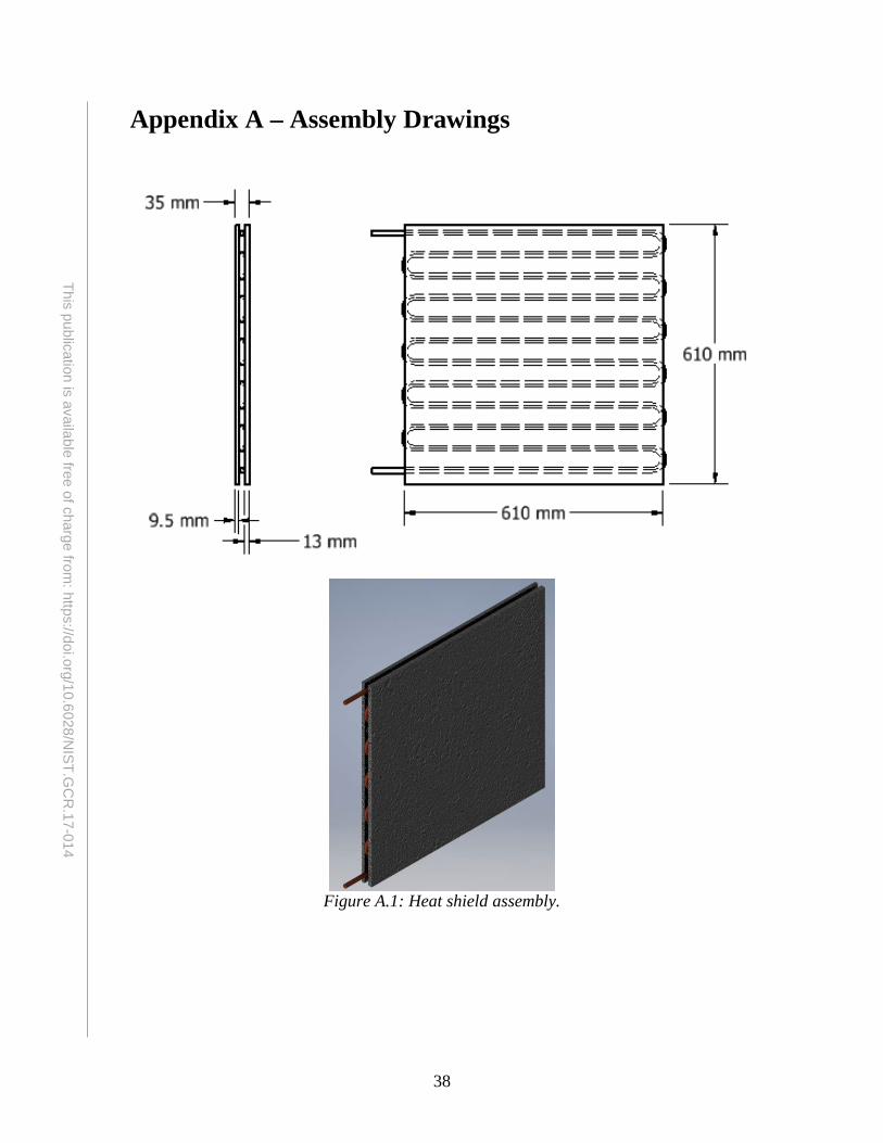
38
This publication is available free of charge from: https://doi.org/10.6028/N
IST.GC
R.17-014
Appendix A – Assembly Drawings
Figure A.1: Heat shield assembly.

39
This publication is available free of charge from: https://doi.org/10.6028/N
IST.GC
R.17-014
Figure A.2: Complete heat shield and frame assembly.

40
This publication is available free of charge from: https://doi.org/10.6028/N
IST.GC
R.17-014
Figure A.3: NIST radiant panel apparatus with repeated exposure heat shield assembly.
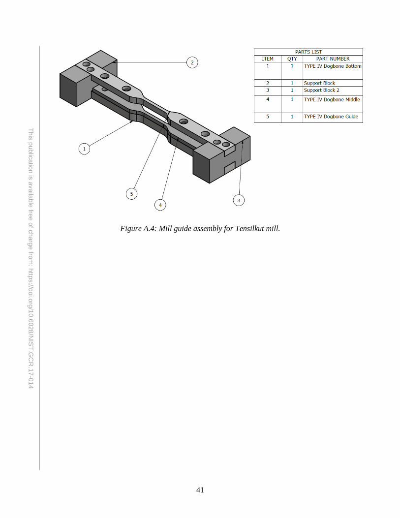
41
This publication is available free of charge from: https://doi.org/10.6028/N
IST.GC
R.17-014
Figure A.4: Mill guide assembly for Tensilkut mill.
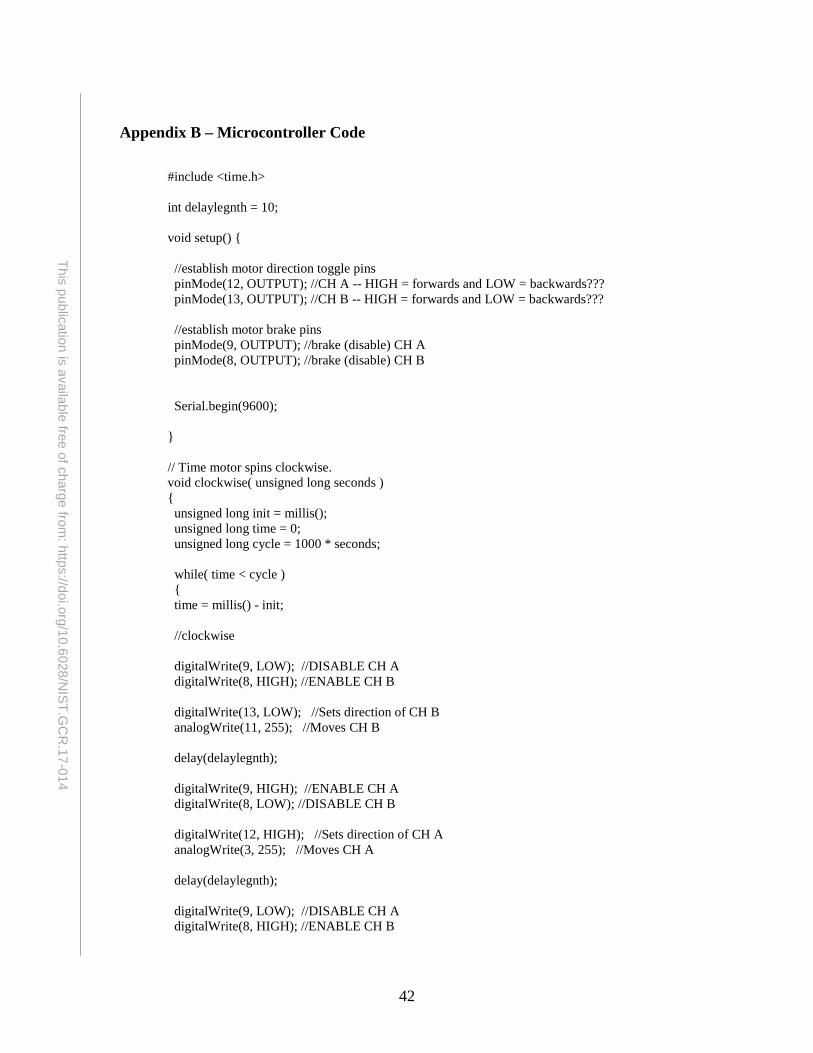
42
This publication is available free of charge from: https://doi.org/10.6028/N
IST.GC
R.17-014
Appendix B – Microcontroller Code
#include <time.h> int delaylegnth = 10; void setup() { //establish motor direction toggle pins pinMode(12, OUTPUT); //CH A -- HIGH = forwards and LOW = backwards??? pinMode(13, OUTPUT); //CH B -- HIGH = forwards and LOW = backwards??? //establish motor brake pins pinMode(9, OUTPUT); //brake (disable) CH A pinMode(8, OUTPUT); //brake (disable) CH B Serial.begin(9600); } // Time motor spins clockwise. void clockwise( unsigned long seconds ) { unsigned long init = millis(); unsigned long time = 0; unsigned long cycle = 1000 * seconds; while( time < cycle ) { time = millis() - init; //clockwise digitalWrite(9, LOW); //DISABLE CH A digitalWrite(8, HIGH); //ENABLE CH B digitalWrite(13, LOW); //Sets direction of CH B analogWrite(11, 255); //Moves CH B delay(delaylegnth); digitalWrite(9, HIGH); //ENABLE CH A digitalWrite(8, LOW); //DISABLE CH B digitalWrite(12, HIGH); //Sets direction of CH A analogWrite(3, 255); //Moves CH A delay(delaylegnth); digitalWrite(9, LOW); //DISABLE CH A digitalWrite(8, HIGH); //ENABLE CH B
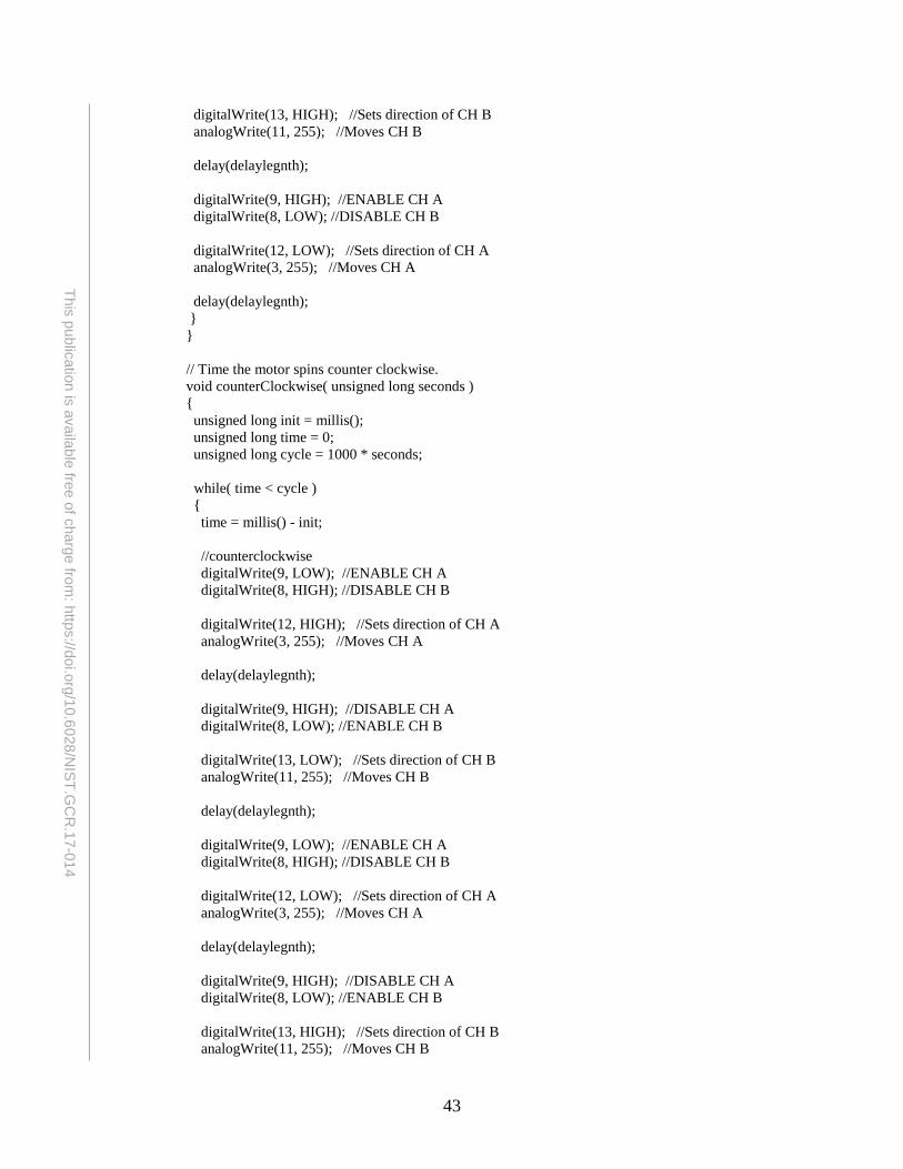
43
This publication is available free of charge from: https://doi.org/10.6028/N
IST.GC
R.17-014
digitalWrite(13, HIGH); //Sets direction of CH B analogWrite(11, 255); //Moves CH B delay(delaylegnth); digitalWrite(9, HIGH); //ENABLE CH A digitalWrite(8, LOW); //DISABLE CH B digitalWrite(12, LOW); //Sets direction of CH A analogWrite(3, 255); //Moves CH A delay(delaylegnth); } } // Time the motor spins counter clockwise. void counterClockwise( unsigned long seconds ) { unsigned long init = millis(); unsigned long time = 0; unsigned long cycle = 1000 * seconds; while( time < cycle ) { time = millis() - init; //counterclockwise digitalWrite(9, LOW); //ENABLE CH A digitalWrite(8, HIGH); //DISABLE CH B digitalWrite(12, HIGH); //Sets direction of CH A analogWrite(3, 255); //Moves CH A delay(delaylegnth); digitalWrite(9, HIGH); //DISABLE CH A digitalWrite(8, LOW); //ENABLE CH B digitalWrite(13, LOW); //Sets direction of CH B analogWrite(11, 255); //Moves CH B delay(delaylegnth); digitalWrite(9, LOW); //ENABLE CH A digitalWrite(8, HIGH); //DISABLE CH B digitalWrite(12, LOW); //Sets direction of CH A analogWrite(3, 255); //Moves CH A delay(delaylegnth); digitalWrite(9, HIGH); //DISABLE CH A digitalWrite(8, LOW); //ENABLE CH B digitalWrite(13, HIGH); //Sets direction of CH B analogWrite(11, 255); //Moves CH B

44
This publication is available free of charge from: https://doi.org/10.6028/N
IST.GC
R.17-014
delay(delaylegnth); } } // Time device should hold in one position. void wait( unsigned long seconds ) { delay( 1000 * seconds ); } void cycle( unsigned long num, unsigned long moveTime, unsigned long exposedTime, unsigned long shieldedTime ) { for( unsigned long i = 0; i < num; i++ ) { clockwise( moveTime ); wait( exposedTime ); counterClockwise( moveTime); wait( shieldedTime ); } // 12 hours delay delay( 43200000 ); } void loop() { // cycle( 5, 4.9, 3, 2 ); //clockwise( 50000 ); }