Embed Size (px)
Citation preview
FAA ADS -14
I,,£
LA.
TECHNICAL REPORT
"ADS -14
A STUDY OF THE FLAMMABILITY
OF MAGNESIUM
By
* Paul Boris
Systems Research and Development ServiceC L EA R I N G H O U S E
FOR FEDERAL SCIENTIFIC ANDTECHNICAL INFORMATION f D C
FEDERAL AVIATION AGENCY C
Washington, D.C. April 1964
A STUDY OF THE FLAABMILITY OF MAGNESIUK
TECHNICAL REPORTADS- 14
by
Paul Boris
Systems Research and Development Service
April 1964
This report was prepared by the SRDS underProject No. 311-2X2 for the AircraftDevelopment Service.
TABLE OF CONTENTS
Page
SlINKARY. .. .. . . . . . . . . .ii
INTRODUCT!ION* .. . . . .e . . . . . 1
DISCUSSION. . . . . . . . . . . . . . . . . . . . . . . . 3
STest Equipment. . . . . . . . . . . . . . . . . . . . 3
Test Specimen Preparations. . . . . . . . . . . . . . 4
Test Procedures ..... . ............ . 5
Test Results. . . . . . . . . . . . . . . . . . . . 5
Ignition Tests (No-Airflow Conditions). . . . . . 5
Ignition Tests (Airflow Conditions). . . . . . . 7
Engine Casting Ignition Tests . ........ 7
CONCLUSIONS .. .. .. . . . . ..... ...... 9
BIBLIOGRAPHY ... . . .. . . .. . . 10
APPENDIX 1
Lists of Illustrations and Tables (24 pages)
II
FEDERAL AVIATION AGENCY
TECHNICAL REPORT ADS - 14
A STUDY OF TRE FLnAABILITY OF MAGNESIIIK
By Paul Boris, Systems Research and Development Service
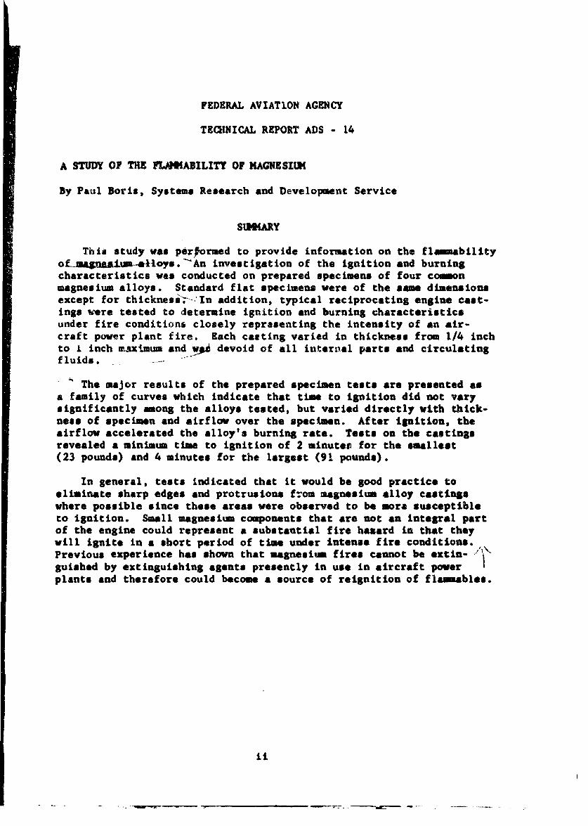
S•MKARY
This study was performed to provide information on the flammabilityoLmaa&A=ium•11.oys.'An investigation of the ignition and burningcharacteristics was conducted on prepared specimens of four commonmagnesium alloys. Standard flat specimens were of the same dimensionsexcept for thicknessi; -In addition, typical reciprocating engine cast-ings were tested to determine ignition and burning characteristicsunder fire conditions closely representing the intensity of an air-craft power plant fire. Each casting varied in thickness from 1/4 inchto I inch maximum and -!* devoid of all internal parts and circulatingfluids... .
The major results of the prepared specimen tests are presented asa family of curves which indicate that time to ignition did not varysignificantly among the alloys tested, but varied directly with thick-ness of specimen and airflow over the specimen. After ignition, theairflow accelerated the alloy's burning rate. Tests on the castingsrevealed a minimum time to ignition of 2 minutes for the smallest(23 pounds) and 4 minutes for the largest (91 pounds).
In general, tests indicated that it would be good practice toeliminate sharp edges and protrusions from magnesium alloy castingswhere possible since these areas were observed to be more susceptibleto ignition. Small magnesium components that are not an integral partof the engine could represent a substantial fire hazard in that theywill ignite in a short period of time under intense fire conditions.Previous experience has shown that magnesium fires cannot be extin- '
guished by extinguishing agents presently in use in aircraft powerplants and therefore could become a source of reignition of flammables.
ii

BL.ANK PAGE

INTRODUCTION
Magnesium as an aircraft construction material is desirablebecause of qualities such as light weight, maheinability and castingcharacteristics, its use is not new in the field of aviation andthe design criteria of components of magnesium have generally beenbased on structural integrity. However, under conditions of properheat balance, it ignites and burns. The degree of ignition resistancerequired of magnesium, therefore, depends on its location in the air-craft.
Generally, magnesium usage is in the form of large castings suchas gear boxesi therefore, it possesses some ignition resistance byvirtue of its mass. In addition, these castings generally containinternal parts and circulating fluids which contribute to the totalamount of heat that can be absorbed before an ignitible temperatureis reached.
Magnesium appears on both commercial and military aircraft whereweight is an important design consideration; for example, one com-mercial airliner contains 360 pounds of magnesium in each powerplant installation. If the magnesium is substituted by anothermetal such as alumintum, on a volume basis there would be a weightincrease of 180 pounds per engine or an overall increase in aircraftweight of 720 pounds.
Previous studiet have been conducted in regard to magnesium firehazards in aircraft and the following are brief summaries of thoilefindings#
(1) Magnesium, except in the form of dust or thin sheet, igniteswith difficulty.
(2) Exposure time necessary to affect burning varies with heatsource, and shape and size of magnesium component.
(3) Magnesium fires are usually initiated by intense fires ofother combustibles.
(4) The addition of small amounts of beryllium appears toincrease the ignition resistance of magnesium.
1Kling, A. L., Blatr, E. A., ?ousin, E. W., Hurst, A. S., andTuello, C. F., Protection of AircraftAgainst Magnesium Fires,Army Air Forces Technical Report 5526, August 1946.
I
m • •....IL.-D
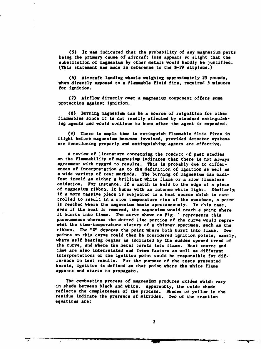
(5) It was indicated that the probability of any magnesium partsbeing the primary cause of aircraft loss appears so slight that thesubstitution of magnesium by other metals would hardly be Justified.(This statement was made in reference to the B-29 airplane.)
(6) Aircraft landing wheels weighing approximately 25 pounds,when directly exposed to a flam able fluid fire, required 5 minutesfor ignition.
(7) Airflow directly over a magnesium component offers someprotection against ignition.
(8) Burning magnesium can be a source of reignition for otherflamnables since it is not readily affected by standard extinguish-ing agents and would continue to burn after the agent is expended.
(9) There is ample time to extinguish flammable fluid fires inflight before magnesium becomes involved, provided detector systemsare functioning properly and extinguishing agents are effective.
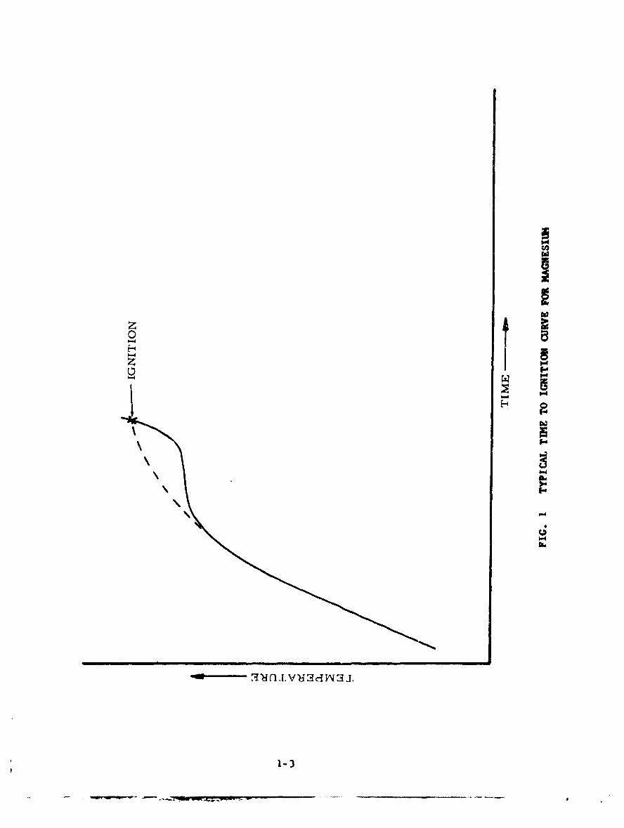
A review of literature concerning the conduct of past studieson the flammability of magnesium indicates that there is not alwaysagreement with regard to results. This is probably due to differ-ences of interpretation as to the definition of ignition as well asa wide variety of test methods. The burning of magnesium can mani-feat itself as either a brilliant white flame or a slow flamelessoxidation. For instance, if a match is held to the edge of a pieceof magnesium ribbon, it burns with an intense white light. Similarl%if a more massive piece is subjected to a heat source which is con-trolled to result in a slow temperature rise of the specimen, a pointis reached where the magnesium heats spontaneously. In this case,even if the heat is removed, the magnesium would reach a point whereit bursts into flame. The curve shown on Fig. 1 represents thisphoenomenon whereas the dotted line portion of the curve would repre-sent the time-temperature history of a thinner specimen, such as theribbon. The "V' denotes the point where both burst into flame. Twopoints on this curve could then be considered ignition points; namely,where self heating begins as indicated by the sudden upward trend ofthe curve, and where the metal bursts into flame. Heat source andtime are also interrelated and these factors as well as differentinterpretations of the ignition point could be responsible for dif-ference in test results. For the purpose of the tests presentedherein, ignition is defined as that point where the white flameappears and starts to propagate.
The combustion process of magnesium produces oxides which varyin shade between black and white. Apparently, the oxide shadereflects the completeness of the process. Shades of yellow in theresidue indicate the presence of nitrides. Two of the reactionequations are:
2

3 Mg + 02 - M.gO + 10,800 Btu/lb. Mg (1)
T 3 Mg + N2 .. Mg3N2 + 2,860 Btu/lb. M5 (2)
Equation No. 1 raflects the normal combustion expected to occur.To sustain burning of bulk magnesium, at least a 5-percent concen-
"t tration of oxygen is necessary (see Footnote 1). Equation No. 2reflects a reaction with nitrogen. Ordinarily, nitrogen does nottake part in a combustion reaction. However, in the case of magne-
•.sium, the temperature of combustion is io great that nitrides areL produced.
The magnesium nitrides react with water vapor in the atmosphereto produce aunonia. (This was indicated after magnesium fire testsby the presence of a strong odor of ammonia in the vicinity of theresidue). The following equation shows this reaction:
Mg3 N2 + 6H 2 0---• • + 3 Mg (OH)2 (3)
Equations Nos. 4 and 5 show the reactions that follow theapplication of water directly to burning magnesium. These reactionsare:
Mg + 2H 20 M---- Mg (OH) 2 + H2 + 6,000 Btu/lb. Mg (4)
2H2 + 02 - 2-- 2120 + 51,600 Btu/lb. H2 (approx.) (5)
These reactions are again attributed to the high flame tempera-ture of burning magnesium, reported to be between 80000 and 90000 F.(see Footnote 1). At such temperatures normal extinguishing agentstend to break down into their elemental components. In some casesexplosive mixtures can result; for example, the reaction of waterwith burning magnesium results in the liberation of free hydrogenwhich, in turn, reacts violently with the oxygen in the air as shownin Equation No. 5.
In addition to magnesium reacting with nitrogen, it will alsoreact with carbon dioxide. The heat of combustion of magnesium innitrogen and carbon dioxide atmospheres is about 25 and 60 percent,respectively, of that in air.
DISCUSSION
Test gquitpent
The heat source for all prepared specimens was a small laboratoryFisher burner which utilized propane gas. Two similar type burnerswere used for different phases of this testing. For tests requiring
3
v - Nil

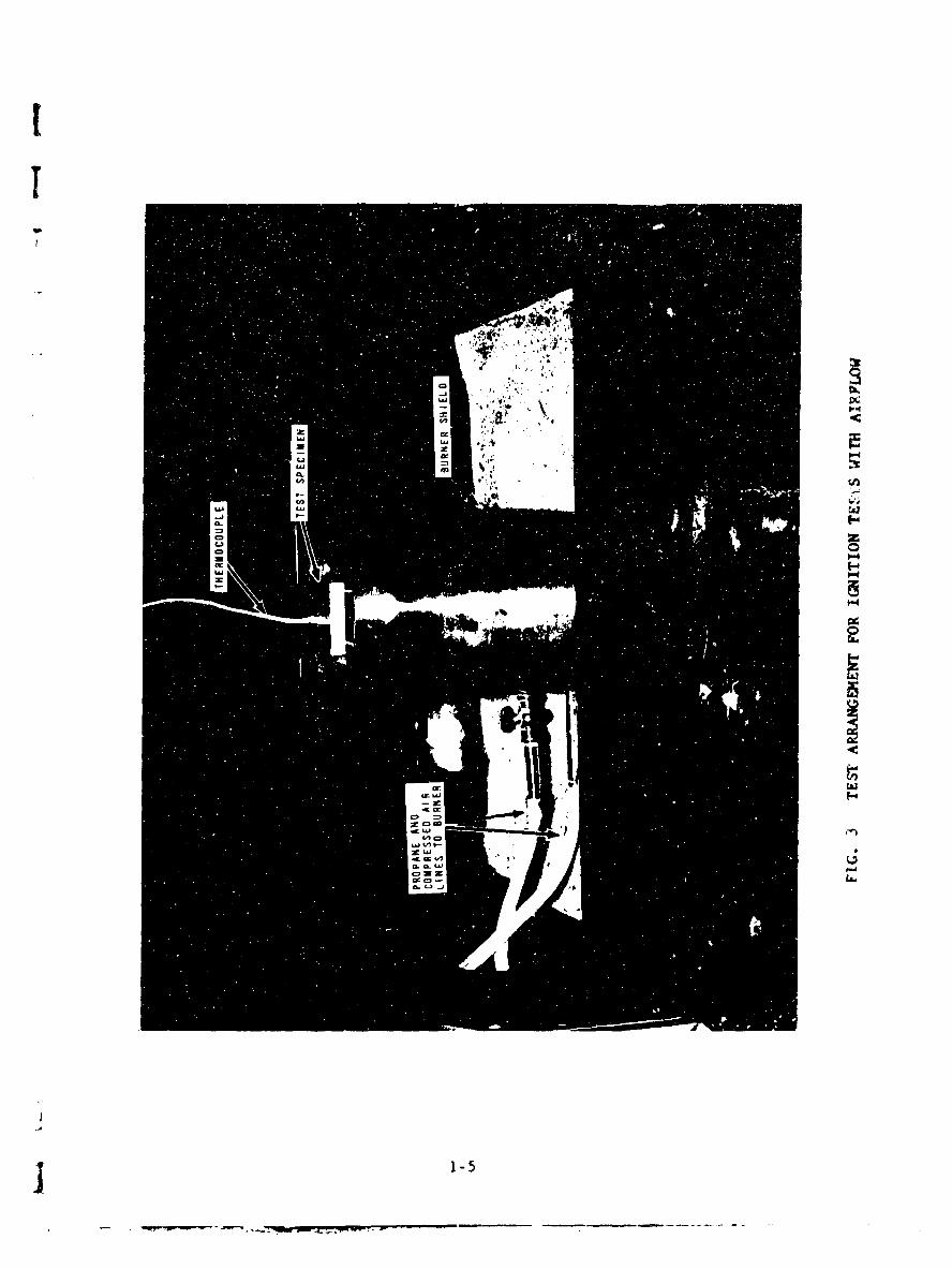
an airflow over the specimen, a burner which operated with a supplyof compressed air was used. A stainless steel housing was fabricatedand placed over the burner to minimise the effects of the airflow onthe flame. Both burners had a 40-millimeter (mm) grid and produceda flame having a temperature of approximately 20000 F. The test set-up for the no-airflow tests is shown in Fig. 2 and for the airflowtests, Fig. 3.
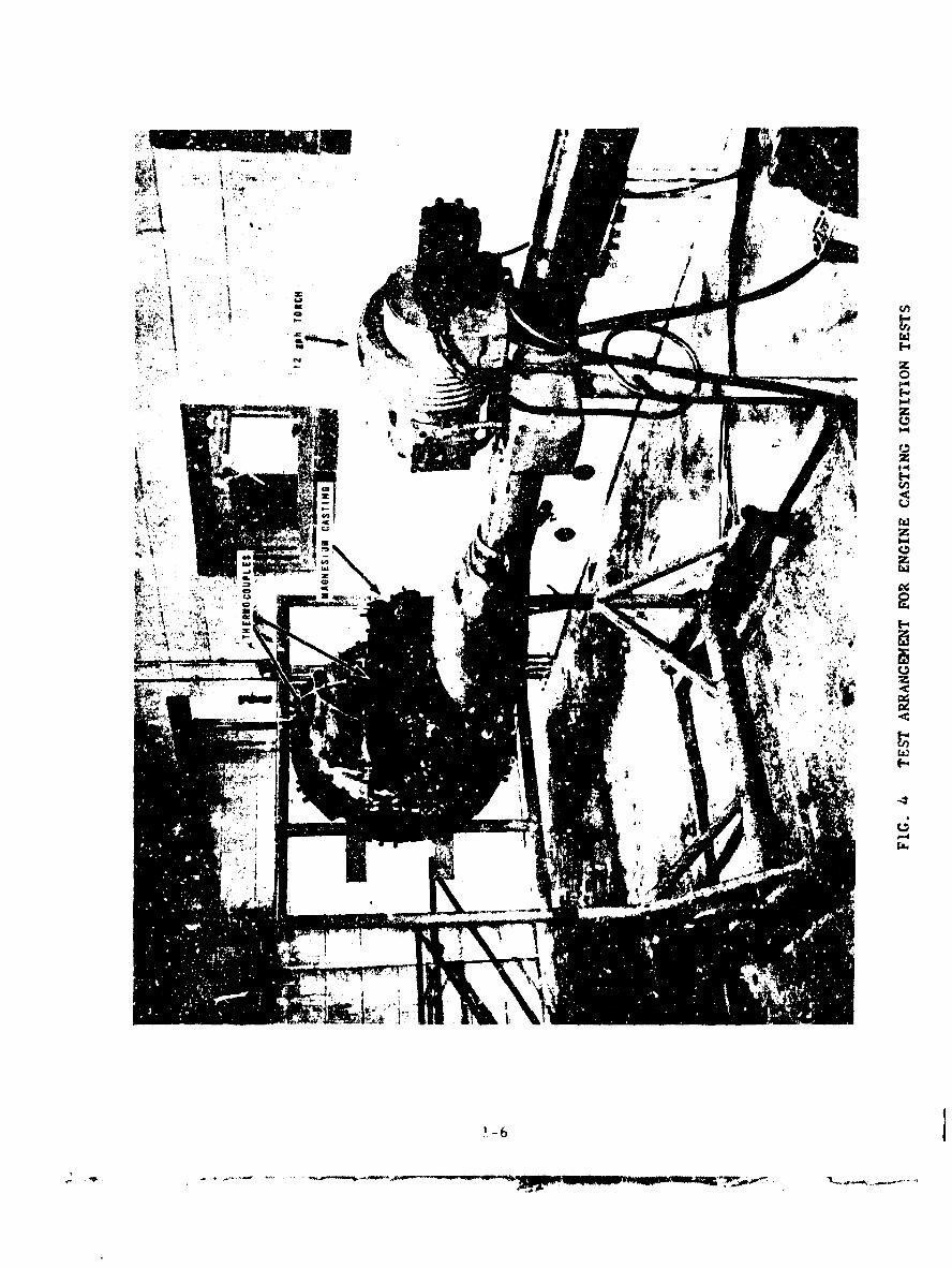
The heat source used for all engine components tests was a com-mercial conversion-type oil burner adjusted to burn 12 gallons ofkerosene per hour. The burner was &quipped with a diffuser havingan elliptical open end of major and minor axes, 16 and 8 inches,respectively. The average temperature of the flame at a distance of8 inches in front of the diffuser was 20000 F. The test setup isshown as Fig. 4.
All temperatures were recorded on Hfnneapolis-Honeywell tempera-ture recorders calibrated for chromel-alumel thermocouples. Bothcircle- and strip-chart type instruments graduated from 0 to 24000 F.were used. Twenty-two gauge chromel-alm-el thermocouple wire withfiberglas insulation was used for the temperature measurement ofprepared magnesium alloy specimens and ceramic-inconel sheath; 22-gauge thermocouple wire was used for temperature measurement of thelarge castings.
The airspeed measurement for tests requiring an airflow condi-tIonwas obtained with the use of an Alnor valometer. The airflowwas produced over the specimen by a 5-horsepower (hp) ceiling fanaspirating air through a2- by 2-foot duct. A sketch of this appara-tus tLs shown as Fig. 5. Control of the airflow was provided byvarying the position of a damper as shown on the sketch. Airflow wasvaried from 0 to 2000 feet per minute (fpm) during tests.
Test Specimen Preparations
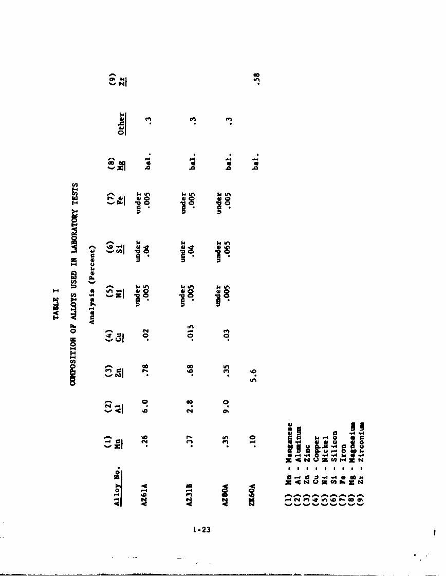
All the prepared magnesium alloy specimens were cut oversize from2k- by 5h-inch bar stock and milled to the desired thickness. Therange of thickness for the tests not requiring an airflow was 0.031to 1 inch. For the tests requiring an airflow, the thickness was1/2 inch. The thermocouple leads were peened into the surface ofthe specimen about I inch apart. The chemical compositions of theprepared magnesium alloy specimens are shown in Table I.
The engine castings were secured to a metal test rig. Holes weredrilled in the castings and thermocouples were inserted at theselocations just under the surface. The locations of the thermocoupleswere chosen to cover both thick and thin sections. Section thicknessvaried from about 1/4 to 1 inch.
4

Test Procedures
The prepared magnesium alloy specimens were placed 1 1/2 inchesfrom the burner grid. This distance was maintained for both the no-airflow and airflow tests. Time-temperature histories were recordedfor each test from the instant the burner was turned on. As soon asa sustaining white flame was observed, the burner was removed andthe tima was noted. This procedure was followed for all tests, bothwith and without an airflow condition.
Test Results
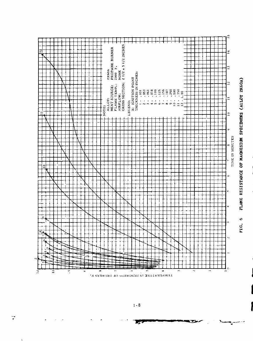
1. Ignition Tests (No-Airflow Conditions): The curves in Figs. 6to 9 present the time temperature to ignition data obtained duringI the no-airflow tests. Photographs of a typical test are shown inFig. 10. The alloys tested were of the magnesium-aluuinum compositionexcept alloy ZK60A which was of a magnesium-zinc composition. Testresults indicated that with the same heat source conditions, ignitiontime increased as the thickness of the specimen increased. Further-more, with an increase in specimen thickness, the shape of the time-temperature curve approaches the solid line portion of that presentedin Fig. 1 of the "Introduction".
Test data pertaining to the thicker specimens show a more accuratepicture of the ignition phenomenon. First, it can be seen that therate of temperature rise decreased with specimen temperature increase.
This is due to the following factors: (1) the specimen is approach-ing the temperature of the heat source, (2) the radiation loss isincreasing in proportion to the fourth power of the absolute tempera-ture, and (3) the specific heat is increasing.
The second noticeable feature of the curves manifests itself as alevelling off of the temperature. This can be attributed to the heatloss approaching the heat input and an apparent phase change to themetal in this particular temperature zone. To illustrate, Fig. 11represents a portion of a phase diagram of magnesium and aluminum.The phase change indicated would probably occur across the boundaryseparating the areas labeled E + L and ( . The C + L area representsthe portion of the phase diagram where a liquid begins to form. InFig. 11, an arbitrary alloy oi 94 percent magnesium and 6 percentaluminum, represented by the dashed line, was selected to show wherethe phase changes occur. From room temperature to 7800 F.6 this alloyexists as two separate solid solutions, S and E . At 780 F. a phasechange occurs. With a further increase in temperature, another phasechange occurs at 10400 F. where a liquid begins to form. At 11450 F.the alloy enters completely into the liquid phase, represented by Lon the diagram. The third change in the shape of the time-temperaturecurve, Figs. 6 to 9, occurs with a sudden rise in temperature. Thiscan be attributed to a completion of the phase change ( t to & + L),but primarily the magnesium undergoes a phenomenon of self heating and
5

raises its own temperature to a point where it will burst into flame.Test data indicate that ignition occurs in the temperature rangedenoted by t + L of Fig. 11, since local melting pruceded ignitionand this ignition temperature is beyoid the inflection point of t~lecurve.
Several tests were conducted to illustrate the phenomenon of selfheating. Figure 12 is the result of one of these tests and is typi-cal of all the tests conducted. The time-temperature history of a2- by 2- by 1/2-inch AZ31B magnesium alloy specimen was recorded as itwas heated in a metal pan utilizing the propane burner as the heatsource. Within a matter of minutes, the temperature began levelingoff and the heat was regulated to maintain a constant temperature ofthe specimen. This temperature was maintained for approximately 1/2hour, and at the end of this period an increase in specimen tempera-ture was noted even though there was no increase in the burner heatoutput. At this point the burner was removed and within the next fewminutes the temperature of the specimen increased to a point where itignited. It appeared that ignition was initiated in the area of anoxide formation. This suggests that local oxidation supplies thenecessary boost in temperature to initiate burning. The oxidationspread over the entire specimen resulting in the entire mass burning.In addition, the edges of the specimen were observed to oxidize andburn initially. From this observation it is deduced that time toignition can be increased by minimizing sharp edges and protrusions onmagnesium alloy castings.
With respect to the thicker magnesium alloy specimens of Figs. 6to 9, the po'nt where the curves undergo self heating, as indicated bya sudden increase in temperature, could be regarded as an ignitionpoint. The thinner specimens heated and burned so rapidly that theself-heating phenomenon was apparently bypassed comqletely. In regardto these thin specimens, the first indication of ignition occurredwith the appearance of a white flame, therefore, the ignition pointco. on to all phases of testing is defined as that where the flame wasinitially observed.
Figure 13 was prepared from the data shown on Figs. 6 to 9. Theordinate was chosen to reflect the effect of area/volume (A/V) ratioon ignition time. A critical section of the curve for all alloys isshown to occur at A/V between 10 and 30. For anA/V value greater than
30, charige in ignition time is insignificant. Conversely, for a valueless than 10, ignition time increases rapidly. These particular dateare based on a specific set of test conditions and cannot be regardedas specific criteria for design. Cnanges in condition such as themagnitude of the heat source, geometry of the specimen and airflowwould result in a displacement of the curves. However, a trend thatsimilar tests would follow is established. The data also point outthe importance that relative surface area has on either increasing ordecreasing the ex,,soue time necessary to cause ignition of the mag-nesium alloy. Large surface areas available for heat transfer having
6
J • .. .......

small volumes to heat, represent a need for caution, particularly ifpotential heat sources are in proximity and if these sources arecapable of temperatures in excess of 10000 F. Considering the alloystested and the conditions under which they were tested, 10000 F.appears to be the approximate temperature at which self heatingbecomes prominent enough to bring the specimen up to its ignitionpoint.
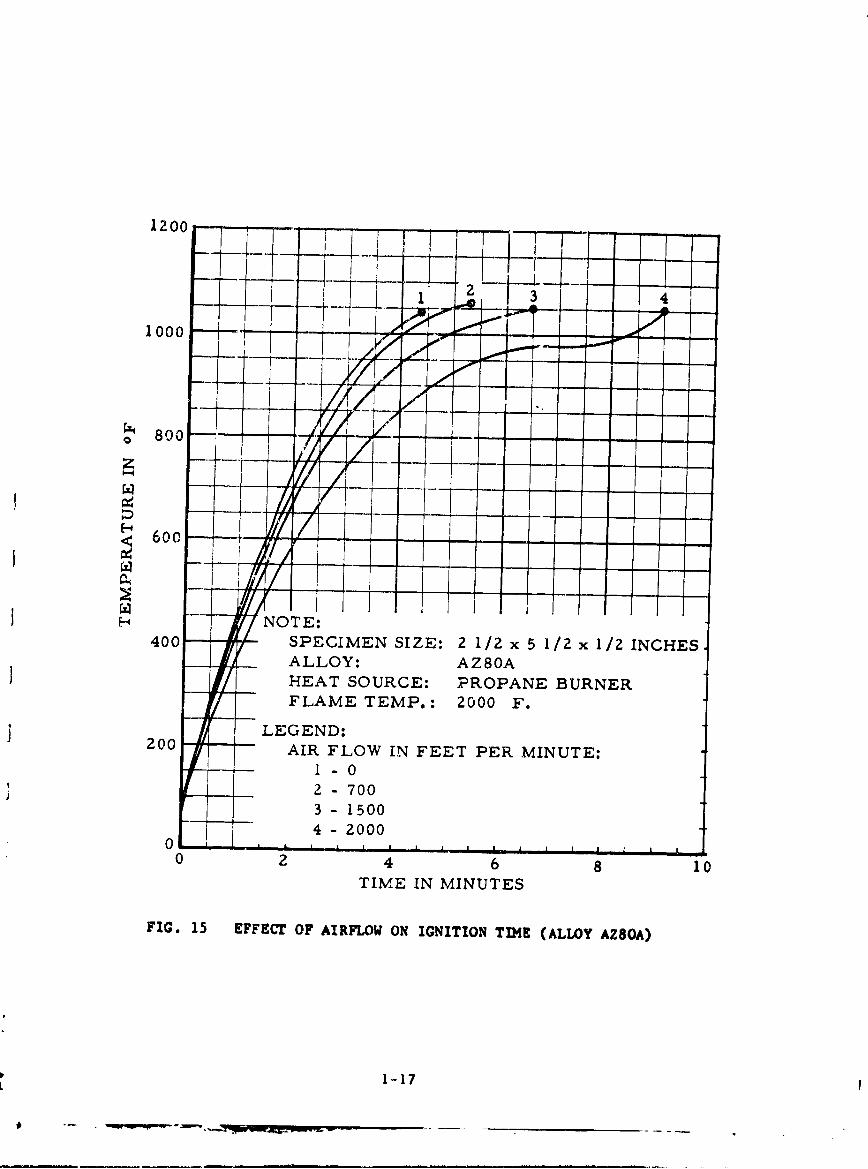
2. nition Tetsa (Airflow Conditions): The next factor con-sidered in the magnesium alloy ignition tests was airflow. Figures14 to 17 show the effect of airflow on the flammability of prepared
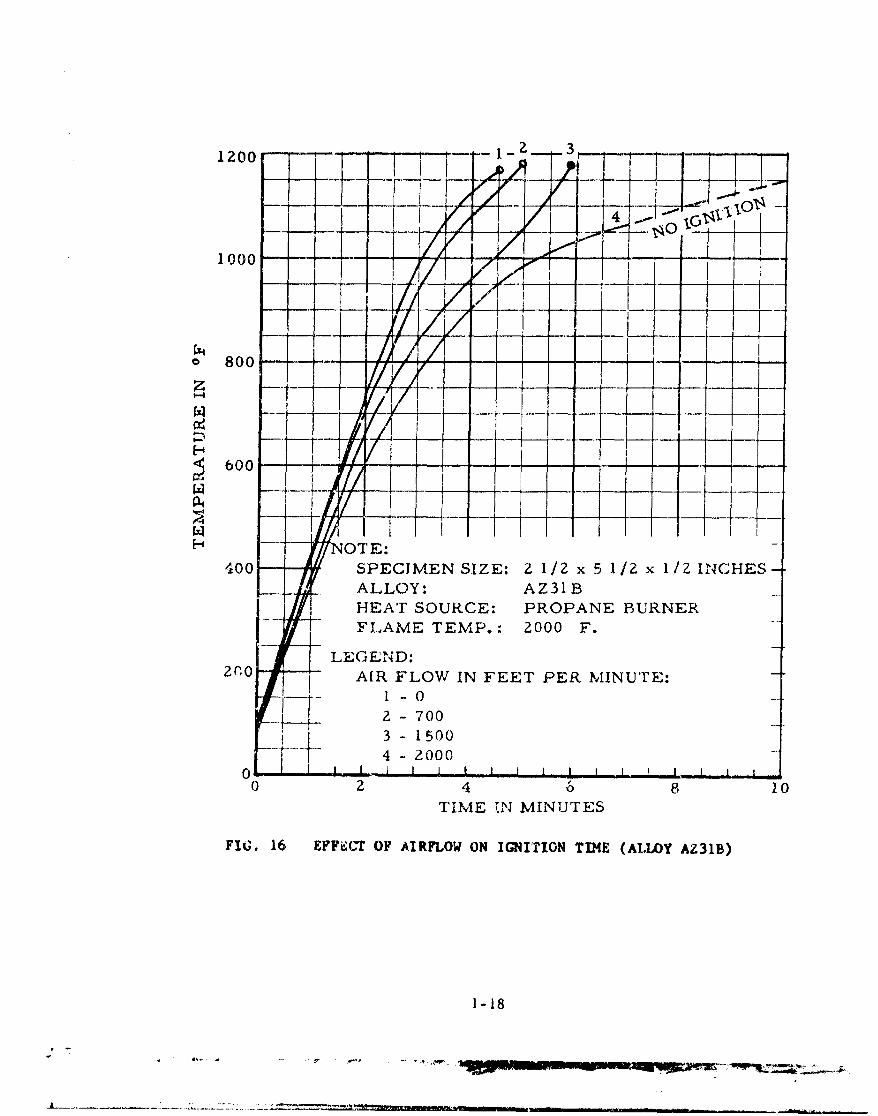
, magnesium specimens. Figure 18 is a curve showing the percentincrease in ignition time with airflow and is based on the averageignition time of the four alloys tested. Airflows ranged from 0 to2000 fpm. Tests indicated that by increasing the flow of air arounda magnesium alloy specimen, the time to ignition is extended; however,once ignition is effected, airflow increases the intensity of themagnesium fire. The only unusual event was that alloy AZ31B did notignite in the 2000-fpm airflow test condition. This is representedby the dotted line in Fig. 16. Since the test conditions to whichthis alloy was subjected were identical to those under which all otheralloya were tested, it was concluded that chemical composition of thealloy in question was a factor. AZ3IB's magnesium content was 95.8percent, whereas all others contained less. The phase diagram indi-cates that 100 percent magnesium melts at 12000 F. The compositionshaving less magnesium to aluminum content melt at lower temperatures.As indicated in Fig. 11, a 94-percent Mg/6 percent Al alloy would'nelt at 11450 F. Since melting and ignition temperatures were observedto appear very close together, it would seem that an alloy of greatermagnesium to aluminum content would ignite at a higher temperature.Under the 2000-fpm airspeed condition, AZ31B alloy apparently did notreach its ignition temperature.
3. Engine Carting Ignition Tests: The third phase of testingconsisted of subjecting engine castings to a flame produced by a12-gallon-per-hour (gph) kerosene burner. These tests were designedto serve two purposes: (1) to obtain indication of the exposure timerequired to ignite a bare magnesium alloy casting, and (2) to deter-mine whether or not burning would be sustained. Table II shows theresults of the tests. Figures 19 and 20 show a sequence of operationduring a typical test and the resulting fire damage to the magnesiumcasting. Time to ignition for the 23-, 81t-, and 91¾-pound castingswere 2, 2, and 4 minutes, respectively. The time that each castingsustained the fire after the burner was shut down was 4, 34, and 50minutes, respectively. It was noted that initial ignition of eachcasting occurred at the thin sections. The largest casting (Test No.3)required more exposure time for ignition to commence, and also sus-tained greater deterioration from fire than the other two castings.This was apparently due to the fact that a more extensive portion ofthis casting had a wall thickness of about 1/4 inch in comparison with
7
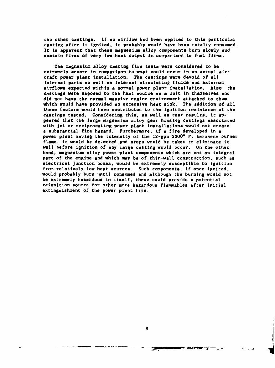
the other castings. If an airflow had been applied to this particularcasting after it ignited, it probably would have been totally consumed.It is apparent that these magnesium alloy components burn slowly andsustain fires of very low heat output in compArison to fuel fires.
The magnesium alloy casting fire tests were considered to beextremely severe in comparison to what could occur in an actual air-craft power plant installation. The castings were devoid of allinternal parts as well as internal circulating fluids and externalairflows expected within a normal power plant installation. Also, thecastings were exposed to the heat source as a unit in themselves anddid not have the normal massive engine environment attached to thenwhich would have provided an extensive heat sink. The addition of allthese factors would have contributed to the ignition resistance of thecastings tested. Considering this, as well as test results, it ap-peared that the large magnesium alloy gear housing castings associatedwith jet or reciprocating power plant installations would not createa substantial fire hazard. Furthermore, if a fire developed in apower plant having the intensity of the 12-gph 20000 F. kerosene burnerflame, it would be detected and steps would be taken to eliminate itwell before ignition of any large casting would occur. On the otherhand, magnesium alloy power plant components which are not an integralpart of the engine and which may be of thin-wall construction, such aselectrical junction boxes, would be extremely susceptible to ignitionfrom relatively low heat sources. Such components, if once ignited,would probably burn until consumed and although the burning would notbe extremely hazardous in itself, these could provide a potentialreignition source for other more hazardous flammables after initialextinguishment of the power plant fire.
8

CONCLUSIONS
Based on the results of laboratory fire tests of prepared mag-nesium alloy specimens as well as a number of magnesium alloy enginegear-housing castings, it is concluded that:
1. There was no significant difference in ignition-resistanceamong the alloys teated and under the conditions which they weretested.
2. Bar stock specimens and castings made of magnesium are moresusceptible to ignition along sharp edges or protrusions.
3. Prolonged exposure at temperatures just below magnesiumalloys' melting temperature could initiate ignition. Test res•ultsindicated that self-heating began at approximately 10000 F.
4. A decrease in the area to volume ratio of the magnesium alloywill increase its resistance to ignition.
5. An increase in airflow over the surface of v magnesium alloywill delay time to ignition, but once ignition Is established, thealloy will burn at a fatter rate than under sttgnant air conditions.
6. Large massive magnesium alloy components are not likely torepresent a 3reet fire hazard problem in aircraft power plant instal-lations because of the obvious large heat requirement necessary toignite them.
7. Small thin-wall magnesium alloy ccmpounents that are not anintegral part of the engine itself but are within a power plant firezone are likely to represent a more serious fire hazard, especiallyfrom reignition of flamnables standpoint since these will resistnormal methods of *:ctinguishment.
9

I BIBLIOGRAPHY
SCarapella, Louis A., Do Solid Magnesium Alloys Burn?, Mellon InstituteK of Industrial Research, August 1945.
* Campbell, JohnA., Appraisal of the Hazards of Friction-Spark Ignition_of Aircraft Crash Fires, NACA-TN-4024, May 1957.
Tuve, R. L., Gipe, R.L., Peterson, H. B., and Neil, R.R., The Use ofTrimethoxyboroxine for the Extinguishment of Metal Fires, Part I,Magnesium, NRL Report 4933.
I McCutchan, Roy T., Investigation of Magnesium Fire ExtinguishmentAgents, WADC TR 54-5, January 1954.
Fassel, W. Martin, Gulbrausen, Leonard B., Lewis, John R., andHamilton,J. Hugh, Ignition Temperatures of Magnesium and MagnesiumAlloys. Report prepared under contract with Technical COd., ChemicalCorps, U. S. Army, July 1951.
Gaydon, A.G., and Wolfhard, H.G., Flames. Their Structure, Radiationand Temperatures, Chapman and Hall Ltd., London, 1960.
3' Van Vlack, Lawrence H., Elements of Materials Science, Addison-WesleyPublishing Co., Inc., 1959.
10-- -w .- - - - -o~-
APPENDIX 1
Lists of Illustrations and Tables

BLANK PAGE
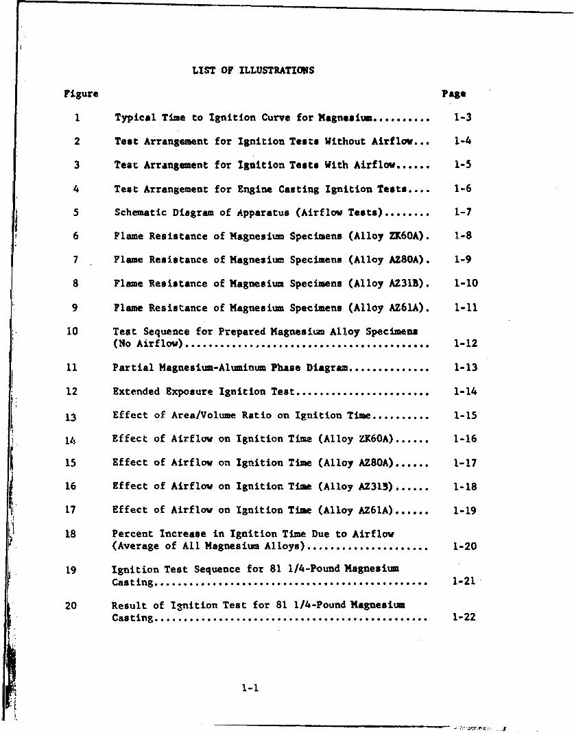
LIST OF ILLUSTRATIONS
Figure Page
1 Typical Time to Ignition Curve for Magnesium .......... 1-3
2 Test Arrangement for Ignition Tests Without Airflov... 1-4
3 Test Arrangement for Ignition Tests With Airflow...... 1-5
4 Test Arrangement for Engine Casting Ignition Tests .... 1-6
5 Schematic Diagram of Apparatus (Airflow Tests) ........ 1-7
6 Flame Resistance of Magnesiun Specimens (Alloy ZK60A). 1-8
7 Flame Resistance of Magnesium Specimens (Alloy AZ80A). 1-9
8 Flame Resistance of Magnesium Specimens (Alloy AZ31B). 1-10
9 Flame Resistance of Magnesium Specimens (Alloy AZ61A). 1-11
10 Test Sequence for Prepared Magnesium Alloy Specimens(No Airflow) .......................................... 1-12
11 Partial Magnesium-Aluminum Phase Diagram.............. 1-13
12 Extended Exposure Ignition Test ....................... 1-14
13 Effect of Area/Volume Ratio on Ignition Time .......... 1-15
14 Effect of Airflow on Ignition Time (Alloy ZK6OA) ...... 1-16
15 Effect of Airflow on Ignition Time (Alloy AZ80A) ...... 1-17
16 Effect of Airflow on Ignition Time (Alloy AZ313) ...... 1-18
1 17 Effect of Airflow on Ignition Time (Alloy AZ61A)...... 1-19
18 Percent Increase in Ignition Time Due to Airflow(Average of All Magnesium Alloys) ..................... 1-20
19 Ignition Test Sequence for 81 1/4-Pound MagnesiumCasting .............. 1-21-
20 Result of Ignition Test for 81 1/4-Pound MagnesiumCasting .................................. 1-22

LIST OF TAKLES
Table Page
I Composition of Alloys Used in Laboratory Tests...... 1-23
11 Engine Casting Ignition Tests.,,.................... 1-24
1-2
II ! i
1-3

444
1-4
urj
C22LL0
abH
c4:
'rH
.9 cr
2c c -5
-U I
f it
IL z
AI-
AlH

SFAN
I
1 TO TEMPERATURERECORDER
THERMOCOUPLE
AIR SPEEDINDICATOR DAMPER
TEST SPECIMEN
AIR FLOW ZFT.
BURNER STAINLESS STEEL TUBE Z, x Z' DUCT
FIG. 5 SCWIATIC DIAGRAM OF APPARATUS (AIRFLOW r8STS)
1-7
-Z N -- - - -
-~ u.
- z
z - 0ý0N '
-) 0
i . 1 14- o<± x
o ..
1:4T
*A S3,lqlq!)q(] .40 si3}f~jNf*if N1 311flIV11I3di"1A

_ _ . .. . . . . .. . . . . . .
z u
- II 111 1 1 I ~zZ co aL r
- - - - - - - - - - - - - - - - - - - - -- - - - - - - - - - - -
Z ti 0---0 - - - - - - - - - - - -i t ~ - - - - - . - ' - - - - - - - -
o IIn
OD r- In^
*-4 333 O3 -40 SG-.fH J3d.L~~V

z ul
- ""-Z -z
0, 0 a. z~o ~ ~ - c5 Z- o - - co Qo , u, o, rf -o-
Sf: . . .•
0 4
.-a'
w -I ý -. x
x u-(-I -- ...... I-Iz CA
- - --. L. - -\
-- ------..-.-.-.- ----- i i ii - -- . -4
"q~zt I t.... 0CZ,
r- 4 0
A S3314'"930 AO SU33 INfIM NJ 3flv 3diN3.I.
-I - 10

I 11
N
Z -0
u In 0
F,-
o 12-114C 0L
-~~ý <- <_ _C__ _'on_ _Z__ _ _ _ _ _ _ _ _ _ _ _ _ _ V_ _ LA O _ _t _ _

FIG. 10 TEST SEQUENCE FOR PREPARED MAGNESIUM ALLOY SPECIMErNS(NO AIRFLOW)
1-12
-ww-k-w---- 'V

94% Mg6% Al
-----1200 OF
• 1145 OF
C+ 1 040 OF
0
w
70 80 90 100% Mg20 10 0% A1
FIG. 11 PARTIAL MAGNESILIM-ALUMINUM PHASE DIAGRAM
1-13

z0
1-4 w
00
fP
F-
o 0
.41-14

00q
-o-to~~-N.PI

12o00 ,
.40
/W/
S600 •/
Sh•' NOTE:400 SPECIMEN SIZE: 2 1/2 x 5 1/2 x 1/2 INCHES
S ALLOY: ZK60AHEAT SOURCE: PROPANE BURNERFLAME TEMP.: 2000 F.
LEC:,,•ND :
AIR FLOW .N FEET PER MINUTE:
1 10
3 -1500-+4 -. 2ooo00
0 2 4 6 5 10
TIME IN MINUTES
FIG. 14 EFFECT OF AIRFLOW ON IGNITION TIME (ALLOY ZX60A)
1-16
1200
1000 1 -.- -7 -. - ------
1 0 0 0..
0, 800/z--
600
I iI --
H NOTE:400 SPECIMEN SIZE: 2 1/2 x 5 1/2 x 1/2 INCHES
ALLOY: AZ80AHEAT SOURCE: PROPANE BURNERFLAME TEMP.: 2000 F.
LEGEND:200 AIR FLOW IN FEET PER MINUTE:
1-02 7003 - 15004 - 20000 p H ' .. p I I p l I I
0 2 4 6 8 10TIME IN MINUTES
FIG. 15 EFFECT OF AIRFLOW ON IGNITION TIME (ALLOY AZ8OA)
1-17
1200
1000 ..--
800 - -
600 77 KS -.. -... !1/-- 1-4 1.. 1 1
H NOTE:41100 SPECIMEN SIZE: 2 1/2 x 5 1/2 x 1/2 INC-.HES
- ALLOY: AZ31 BHEAT SOURCE: PROPANE BURNERFLAME TEMP.: 2000 F.
LEGEND:2(n0 AIR FLOW IN FEET PER MINUTE:
I -02 - 7003 - 15004 - 2000
0i I I I 1 I I I I I I I I
0TIME 11N MINUTES
FIG. 16 EFFECT OF AIRFLOW ON IGNITION TIME (ALLOY AZ31B)
1-18

i200
6000 ~iI-
ooo -/" w-----
F800 T P 2 0
2600
0N 0 "1 81
400 SPCIEN SIZE: 2 1/2 x 5 1/2 x I/2 INCHES_ALLOY:AZ61A
[ -HEAT SOURCE: PROPANE BURNER--- •--- FLAME TEMP. : 2000 F.
SLEGEND:-
200 - AIR FLOW IN FEET PER MINUTE:1 -02- 700
r 3 -1 5004 2 000
0 1 - I I I I I I I I i I I I I I0 2 4 6 8 10
TIME IN MINUTES
FIG. 17 EFFECT OF AIRFLOW ON IGNITION TIME (ALLOY AZ61A)
1 -19

100
SPECIMEN SIZE: 2 1/2 2< 5 1/2 x 1/2 INCHES
1~4
z/
0
-I I
S50 /
100,
z
0-- --0 500 1000 1500 2000
AIR FILOW IN FEET PER MINUTE
FIG. 18 PERCENT INCREASE IN IGNITION TIME DUE TO AIRFLOW(AVERAGE OF ALL MAGNESIUM ALLOYS)
1-20 .

FIG. 19 IGNITION TEST SEQUENCE FOR 81 1/4-POUND14AGNESIUMb CASTING
1-21
- U

FIG. 20 RESULT OF IC44ITION TEST FOR 81 1/4-POUNDMAGNESIUM CASTING
1-22)
, ,a a ,a
.0. .0.0'.4
0 8 08
oG
o C4 -
o 0
X• 44 tQ* m 00*
00
0- C4 l -4LnD O
1-23

.rcnr4%
pal A$1
0
9U
'a
caa
0 90-4 F0
94 C4 N- 4- 4 C
91
1'4
0 6 00W
N ' "4 u 0
N~EO 41
.4-1
C44
1-144