Embed Size (px)
Citation preview

LIBRARY R O Y A L A I R : " --, ;~ F;:T i; ~!~ ~! ~, B L I S H M E N T
• ( ~ i ~ o
M I N I S T R Y OF SUPPLY
R. & M. No. 2980 (16,98S)
A.R£ . Technical Report
A E R O N A U T I C A L R E S E A R C H COUNCIL R E P O R T S A N D M E M O R A N D A
A Study o f the Aircraft A r r e s t i n g - H o o k
- , . .Bounce Problem
J. THOMLINSON, Ph.D.
Cr~n Copyrig~ Resema
L O N D O N " H E R M A J E S T Y ' S S T A T I O N E R Y O F F I C E
. ' 1957,
T H I R T E E N S H I L L I N G S NET
A. Study of the Aircraft Arresting-Hook Bounce Problem
By
J i THOMLINSON, Ph.D.
COMMUNICATED BY THE PRINCIPAL DIRECTOR OF SCIENTIFIC RESEARCH (AIR),
MINISTRY OF SUPPLY
Reports and Memoranda No. 2 98o*
May, 1954
Summary.--The kinematics of an arresting-hook unit are studied in order to determine, within the limits of the assumption of a perfectly rigid hook unit, the damper force necessary to control hook bounce. The necessity for a smooth deck and the desirability of small trail angle for the hook unit are demonstrated from several aspects. The design requirements for a hook damper unit are discussed in all their functional aspects and methods are given for determining the up-swing motion of an arresting hook unit immediately following engagement of an arresting wire. The behaviour of arresting wires after being depressed by the passage of aircraft wheels is also outlined.
1. Introduction. T h e operation of deck landing depends to a large degree .on the abil i ty of the aircraft arresting hook to engage a cross-deck centre-span of an arresting gear. I t is most desirable, for many reasons that the hook upon coming within reach of the deck shall engage the first centre-span which crosses it path ; or expressed another way, the hook on reaching the deck shall not bounce, or if this ideal is unobtainable then the bounce (in terms of clearance between the deck surface and the underside of the hook) shall be measurable only in fractions of an inch. If this objective is achieved then the arresting wire will be engaged by the hook before the aircraft wheels touch down and disturb the arresting wires, since a hook installation is usually designed so that the hook lies some 2{ ft or more below a line which is tangent to the underside of the main wheels and parallel to the deck or ground, when the aircraft is in its approach at t i tude. If, however, the hook, having failed to engage an arresting wire before the main wheels touch down, is then confronted by a wire which has been disturbed by the aircraft wheels, then the chances of the hook engaging such a wire may be greater or less than tha t of engaging all un- disturbed wire (see Appendix V). In the case of a nose-wheel aircraft with its main wheels on the ground or deck, the chances of engaging a wire are greater when in a nose-up at t i tude than when in a nose-down attitude, because in the nose-up att i tude the hook suspension is trailing at a smaller angle with respect to the deck, than when in a nose-down attitude, with a result tha t the hook is in a more favourable at t i tude for engagement with the wire, since the small trail angle is less conducive to hook bounce. This condition is one of first importance when considering arresting gears as an overshoot safety measure bn land runways.
*R.A.E. Tech. Note N.A.g63~ received 12th August, 1954.
!
One has only to witness a few deck landings of aircraft fitted with hook installations having, alternatively, good and poor anti-bounce properties, in order to appreciate the existence of a problem having a fundamental bearing on the safety of deck landing operations. However, the factors which contribute to this bounce phenomena are not at all obvious, and realistic theoretical t reatment becomes most intractable.
The problem has been shirked in the past to some degree by employing a large number of cross-deck centre spans, on the supposition tha t the hook must surely engage one of many, if not the first.
However with the steadily increasing landing speeds of successive generations of deck-landing aircraft, without a corresponding increase in the landing area (particularly lengthwise), but rather with a reduction in the area of deck across which arresting wires can be stretched, it is considered imperative that the hook bounce problem should be faced with determination.
The advent of the angled (or canted) flight deck might be regarded as a possible reason for relaxing the at tack on the bounce problem but it is considered that nothing but good would result if engagement of the hook with a wire could be guaranteed with a high degree of certainty, and regarding the angled deck property of the ability to fly round again, as a safety precaution to be used only rarely.
Some years ago, following a period when hook bounce in the opinion of many left much to be desired, a recommendation was made that hook damper units should provide a holding down moment equal to three to four times the gravity moment- - the gravity moment being equal to the moment produced by gravity on the hook installation when its axis was horizontal, This recommendation led to a general improvement, many installations being provided with more moment effort than that proposed, but nevertheless such a recommendation had little funda- mental backing and was more in the nature of an empirical rule to be replaced as understanding of the problem developed. The increase of landing speeds, without an increase in landing area, demands better bounce control than is now being accepted--the increase in speed makes a hook more prone to bounce yet if it does bounce tile time to return to tile deck should be inversely proportional to the engagingspeed.
Fig. 1 illustrates a typical layout of a hook installation and shows tile parts with their names as will be used in the subsequent text. The element known by common usage as the hook damper, is not necessarily a damper in the strict mathematical sense, and in the U.S. Navy is known by the more lengthy but more exact title of: Arresting-hook shock absorber and hold-down device.
2. The Nature of Hook Boume.- -The popular conception of bounce, or tile ability to rebound, is probably well illustrated by the releasing of, say, a golf or tennis ball from a height of three or four feet above a hard surface, when it will rebound to a height of some 80 per cent of tha t from which it was released. If this experiment is repeated using a 2-in. diameter solid steel ball (1¼ lb), dropped on to a concrete or steel slab, the rebound will be negligible--a few inches rebound might be obtained with a steel slab four or six inches thick. However, rebound will be more evident as the size of the steel ball is reduced compared with the thickness of the steel slab. I t is evident tha t the conditions controlling the degree of bounce are complex and depend, amongst other things, upon the hardness, resilience and rigidity of the two elements. Dropping an aircraft arresting hook* from several feet on to a concrete runway or steel decking is not followed by any rebound.
Next consider a hook unit mounted on a hinge as shewn in Fig. 2a. Following free fall through an angle of 90 deg on to a hard horizontal surface, there is unlikely to be any rebound of the hook-- the force of gravity appearing to have little difficulty in resisting any tendency to rebound. Next consider, as shown in Fig. 2b, a hook unit falling freely through an angle of 180 deg and the hook striking a hard vertical surface. In this case, if rebound
*By ' hook ' is meant that part which in current British practice is removab!e from the hook suspension,

is small, gravity forces will have relatively little effect on the rebound and a test shows that the hook unit does in fact only rebound some 10 deg or so. I t will be noted that follow- ing impact, the suspension is set vibrating, this being clearly visible if the suspension is slender and flexible.
I t is clear therefore that the bounce properties of an arresting hook during landing cannot be explained in terms of the simple percussion examples described above, these effects, if any, making only a small contribution to the hook bounce behaviour. The next section shows that the initial hook bounce is caused by a wedge action between the hook suspension and the deck, the ' wedge ' being the angle between the deck and the descent path of the aircraft.
3. The Kinematics of Arresting-Hook Bounce.--3.1. Touch-down on a Smooth Landing S u r f a c e . - In Fig. a let AB represent the arresting-hook unit of an aircraft descending along a straight path, at an angle ~, on to a carrier deck, such that the hook hinge point A successively occupies the positions A, A0, A1 and A2 after approximately equal intervals of time. Tile hook moves parallel to the aircraft until it reaches the position B0, when it strikes the deck. If now the hook stays in contact udth the deck, the hook positions corresponding to the hinge point positions A1 and As will be B1 and B2.
The sudden arrestment of the vertical motion of the hook, imparts a sudden rotational motion to the hook suspension--the hinge point still continuing in its straight inclined path at a uniform velocity.
The determination of the duration and value of the reaction between the hook and the deck has not been possible by theoretical analysis. If this were possible then one co..uld determine the angular velocity of the hook suspension and hence determine tile bounce trajectory. An alternative approach to the problem is to assume that the hook, following impact with the deck, maintains contact with the deck, and then determine what conditions are required to satisfy this prescribed motion.
If it is assumed that the hook suspension is rigid, i.e., that AB remains a straight line, and tha t the hook~ B remains continuously in contact with the deck then it cal~ be shown (see Appendix I) that
v sin c~ v - - sin ~ sec/~
" a c o s ~ a
and
where
= -- ( d sin ~ ) tan fl . .
fi = sin ~ ) c~ss 8 ? .
= ¢~ tan ~ . . . . . . v is the speed of approach
the angle of approach a the length of the hook unit
und
d =
=
. . . . . . . . . . . . ( 1 )
. . . . . . . . . . . . ( 2 )
the trail angle of the hook suspension, i.e., the angle between tile deck line and the line joining the hook hinge point and point of contact between deck and hook
a s i n
d~ dt ' the angular velocity of the hook unit
d 2 ~ di ~- , the anguiar acceleration of the hook unit
a

From equation (1) (and Fig. 3) it follows that immediately on contact of the hook with the deck, the hook unit is subjected to all angular velocity as a result of the impulsive blow it receives from the deck, and that thereafter, if contact is maintained with the deck, this angular velocity diminishes. Unless, therefore, the hook suspension is subjected to an angular acceleration of a value not less than that given by equation (1), the hook will leave the deck. Examination of equations (1) and (2) shows tha t both #and $ decrease with a decrease in 8, and that when 8 approaches ½= (i.e., the hook hanging vertically) both ti and fi approach infinity, i.e., bounce is inevitable. I t should be noted tha t ~ is directly proportional to the sinking speed (v sin ~) and that/~ is directly proportional to the square of the sinking speed. Here then, it is considered, lies the main cause of the bounce characteristics of an arresting hook when landing ; i.e., on the instant that the hook reaches the deck, the angular velocity to be generated by the hook suspension to satisfy the condition that the hook does not pass below the plane of the deck; is greater than the angular velocity required at any subsequent instant if continuous contact is to be maintained • in fact for continuous contact the angular velocity at any instant (except the instant of first contact) is less than that at tile preceding instant, and such a condition can only be maintained by subjecting the hook suspension to an angular acceleration, the force for the required accelerating couple being provided by the damper unit.
The length of an arresting-hook unit is generally established such that the vertical distance of the hook below the hinge point shall be not less than some value established from certain geometrical properties of the aircraft, hence, in equations (1)and (2) this vertical distance d is used as an alternative to the hook length a. Thus, ill order to prevent hook bounce following first contact on a smooth deck from a sinking approach, the hook unit must be subjected to a 'holding down ' moment which will impart an angular acceleration of (v/d sin a)~ tan 3 #. The factors v, d and ~ are to a large extent fixed for a given aircraft and 8 is the only variable. Thus tan 3 8 is a measure of the holding down effort to be provided by the hook damper unit. Whilst for reasons of stowage space and weigt~t consideration it is desirable to make 80 approach ½= as nearly as possible (so tha t the hook would hang down vertically), it follows from the above reasoning tha t the problem of ensuring no bounce on first contact becomes increasingly difficult and tends to an impossibility as the value of #0 approaches ½~. The following table illustrates the increase in effort required as 8 is increased, since the effort required is directly proportional to tan 3 8 "
8 (deg) 45 50 55 60 65 70 75 80 85 90 tan3 8 1 1.7 2.9 5.2 9.9 21 52 180 1500 oo
Fig. 4 shows the variation of tan 8 and tan s 8 with 8 and thus indicates the variation of -- /~ and fi with 8.
For values of 8 between 50 and 80 deg an increase of only 5 deg requires roughly twice the damper effort required to resist hook bounce, whilst for values of 8 above, say, 75 or 80 deg the bending strength of the average hook suspension would probably prohibit the use of a damper effort capable of resisting hook bounce. I t is of interest to note that as 8 is reduced the length of the hook unit a is increased (for a fixed value of d) and the moment of inertia of the hook suspension will therefore increase. Then if the holding down moment is T we have "
I T = fi g , where I is the moment of inertia of the hook unit about its hinge point
(: 4 = sin 'tan3 8. × C(dcosec 8) 3, where C is a constant,
= Cd(vsin ~)~ sec ~ 8.
Therefore, despite the increase of the moment of inertia of the hook unit with a reduction in #, the damper effort to resist bounce is reduced, since sec3fl diminishes as 8 is reduced. The increase m weight of the hook unit, by virtue of an increase in length, will be offset to some. degree by the reductior~ in weight of the correspondingly less powerf.~ damper unit,
4
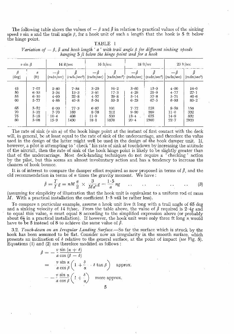
The following table shows the values of --/} and/~ in relation to practical values of the sinking speed v sin c~ and the trail angle/3, for a hook unit of such a length that the hook is 5 ft below the hinge point.
TABLE 1 Variation of -- ¢, ~ and hook length ' a ' with trail angle/3 for different sinking speeds
hanging 5 f l below the hinge point and for a hook
v sin/3
/3 (deg)
45 50 55 60
65 70 75 80
a
(ft)
7"07 6"53 6"10 5" 77
5.52 5.32 5.18 5.08
14 ft/sec
(radn/sec) (radn/sec 2)
2.80 7-84 3.34 13.3 4.00 22.8 4.85 40.8
6.00 77.3 7.70 163
10-4 408 15.9 1430
16 ft/sec
(radn/sec)
3" 20 3"81 4"57 5-54
6-87 8.78
11-9 18.1
(radn/sec °-)
10"2 17"3 29"8 53"3
101 212 533
1870
18 ft/sec
(radn/sec) (radn/sec z)
3-60 13-0 4.29 21-9 5.14 37-8 6.23 67.5
7.72 128 9.90 269
13.4 675 20.4 2360
20 ft/sec
- ¢
(radn/sec)
4"00 4" 77 5"71 6"93
8.58 11.0 14.9 22.7
(radn/sec 2)
16"0 27.1 46 '6 83 '2
158 332 832
2920
The rate of sink (v sin 0c) of the hook hinge point at the instant of first contact with the deck will, in general, be at least equal to the rate of sink of the undercarriage, and therefore the value used in the design of the latter might well be used in the design of the hook damper unit. If, however, a pilot is at tempting to ' Check ' his rate of sink at touchdown by increasing the att i tude of the aircraft, then the rate of sink of the hook hinge point is likely to be slightly greater than that of the undercarriage. Most deck-landing techniques do not require a ' checking' action by the pilot, but this seems an almost involuntary action and has a tendency to increase the chances of hook bounce.
I t is of interest to compare the damper effort required as now proposed in terms of $, and the old recommendation in terms of n times the gravity moment. We have :
T a 3 1-5 fl = I g = n M ~2 × M ~ g -- a ng . . . . . . . . . . (3)
(assuming for simplicity of illustration that the hook unit is equivalent to a uniform rod of mass M. With a practical installation the coefficient 1.5 will be rather less).
To compare a particular example, assume a hook unit five It long with a trail angle of 65 deg and a sinking velocity of 14 ft/sec. From the table above, the value of fi required is 2.4g and to equal this value, n must equal 8 according to the simplified expression above (or probably about 6½ in a practical installation). If however, the hook unit were only three ft long n would have to be 5 instead of 8 to achieve the same value of ft.
3.2. Touch-down on an Irregular Landing Surface.--So far the surface which is struck by the hook has been assumed to be fiat. Consider now an irregularity in the smooth surface, which presents an inclination of 6 relative to the general surface, at the point of impact (see Fig. 5). Equations (1) and (2) are therefore modified as follows:
v sin (e + ~) a c o s (/3 - -
_ _ v sin 0~ (/1 a ~0~/3 k
_ v sin c~ ( - 1
d t an /3 ) + ~ approx.
+ ~ ) more approx.
5

or - - ~ s i n e t a n $ 1 + . .
and fi \ ~ ~os tan ~ 1 + approx.
or ( d sin c~)~ t an3 , ( 1 + ~ ) ' .
(4)
(s)
Note.--The above approximations are valid only when ~ and ~ are small (say, up to eight deg) and ~ tan/~ is small (say for example d = 5 deg and $ = 70 deg).
Therefore, the ratio of the impulsive angular velocities and the angular accelerations required to ensure continuing contact, for the two cases of a smooth deck and with a local excrescence of
( : ) ( ;)' inclination 8, are 1 + and 1 + respectively. It is to be emphasised, however, that the
value for • in the case of excrescence is that value required to ensure continuous contact with the excrescence with a slope of d--i t does not ensure continuous contact with the deck after the hook has passed the excrescence. For instance in Fig. 5a, assuming that the hook has traversed the rearward slope of the symmetrical excrescence whose sides each have an inclination of with respect to the flat plane of deck ; then as it passes over the crest the angular velocity must (if continuous contact is to be made) change from
_ v s in (~ + ~) t o v s in (c¢ - - 8) a co s (~ - - 8) a co s (~ + 8)
This change in angular velocity, which equals approximately v/a. sin 2~/cos 13, must take place during the period in which the hook is traversing the crest of the excrescence, so that if the crest is sharp, i.e., the change of slope is instantaneous, the change ill angular velocity must be instantaneous if continuing contact is to be maintained. Thus an impulsive force is required to thrust the hook down to the profile of the forward side of the excrescence.
To summarise therefore, if the hook is to maintain contact with sudden changes in slope of the deck, the hook unit is subjected inevitably to sudden changes in angular velocity which are generated as a result of impulsive forces. When the hook meets an upward slope the impulsive force is the positive reaction between the deck and hook, but when the hook meets a downward slope there cannot exist a negative impulsive reaction between the hook and deck, and hence contact is lost since the damper is quite inadequate for providing the necessary impulsive down- ward force.
Therefore in specifying the touch-down area it is essential to emphasize that any changes in slope must be very gradual and if changes are unavoidable, such as with deck lights and arresting wire supports, then these should be ramped to as fine a degree as possible--preferably with a transition curve. Nevertheless, in spite of this qualification every effort should be made to provide a perfectly flat surface in the touch-down area.
3.3. Trajectory of a Hook Bounce.--With the design of hook installations and damper units now in general use it is probably impractical to provide restoring moments to the hook unit, sufficient to provide values of/~ as indicated to the right-hand side and lower part of Table 1, and it is of interest to examine the trajectory of the hook bounce following the first impact with the deck. In Fig. 6 assume that a hook unit of length a is approaching with a velocity v at an angle ~ with respect to the deck, and on contact acquires an impulsive angular velocity
6
o~ - - t}0 and thereafter is subjected to a uniform angular acceleration of/~. Assume tha t -f}0 and ~ are of such values tha t hook bounce occurs. Then tile height y of the hook t ra jec tory at any t ime t after the ins tant of impact is given by
y =- a sin 80 -- vt sin ~ -- a sin {80 --(t~0 t -- ½/~Z2)} . . . . . . . (6)
This as a m a x i m u m when dy/dt = O, i.e., w h e n :
v sin cos {80 -- ( t i o t - ½P t~)) . . . . . . . . . . . . . (7)
a( 0- t t) -
T h e hook will contact tile deck again when :
sin 80 = v t sin 0~ + sin {80 -- (#0t -- 1/~t2)} . . . . . . . . . . . . (8) a
t in equations (7) and (8) is probably determinable only by trial-and-error, and hence it is most convenient to plot the t ra jec tory of the hook using equat ion (6) and then measure off the required m a x i m u m height and length of bounc e - - t h e lat ter on either a t ime or a space scale.
Fig. 7 illustrates a family of bounce trajectories following various rates of descent of a hook uni t on to a flat surface, when the initial trail angle is 80 deg and the impulsive angular velocity is resisted at 50 radians per second 2. Fig. 8 shows the variat ion of height and t ime of the bounce t ra jectory with sinking speed. From this figure it is seen tha t for s inking speeds up to 2 .6 ft/sec there is no hook bounce, whilst at 5 .0 ft/sec the height of the bounce is only 1 in., but as the value of tile sinking speed increases further the height of t h e hook t ra jectory increases rapidly, being 30 in. for a sinking speed of 10 ft/sec. The trail angle of 80 deg used in this example is for reasons already given, excessive, and if it were reduced to 70 deg sinking speeds of up to 7 .3 ft/sec would not produce any bounce, and if it is permissible to assume proport ionate ly* with the 80-deg case, then sinking speeds of up to 14 ft/sec might be possible whilst l imit ing the height of the hook t ra jectory to 1 in. I t seems likely therefore tha t if in specifying tha t some small increment of bounce, say 1 in., is pe rmi t ted instead of zero bounce, then it is very likely tha t the design problem is considerably eased.
3.4. Arresting Hook Meeting an Obstruction whilst Trailing Along the Deck.--Until now, a t ten t ion has been directed mainly to the period between the hook first contact ing the deck and the main wheels contact ing the deck. During this time, the hook will, assuming no bounce, have had the oppor tuni ty of engaging at least one arresting wire--poss ibly m o r e - - a n d the object of the s tudy has been to see what must be done to ensure engagement in this period. Unt i l such t ime tha t successful engagement during this period can be guaranteed wi th ce r t a i n ty - - which is un l ike ly - - then consideration must be given to the bounce problem during the subsequent period.
W h e n the wheels of an aircraft, in contact with the deck, pass over arresting wires, the la t ter take a fraction of a second** before they recover from the deck with a sufficient clearance to facilitate the beak of the arresting hook passing benea th them and so making engagement . W i t h the wire lying on the deck there is a chance, especially so if the trail angle is large, such as wi th a nose-wheeled aircraft wi th all three wheels on the deck, tha t the rope will strike the unders ide of the hook beak. Thus, instead of engagement being made the hook is ' kicked up ' and may not, unless adequate hook damping is provided, be re turned to the deck i n t ime to have an oppor tun i ty of engagement with the subsequent wire. In addi t ion the arresting wires are suppor ted clear of the deck by elements which even in the best of designs present a small
*The mathematical expression for maximum height of hook trajectory is too complex to establish the truth of this assumption and one should rework Figs. 7 and 8 for the new value (70 deg) of 8o.
**The time of recovery depends on the disposition of the rope supports with respect to aircraft wheels, the tension in the rope, and the line density of the rope. This increment of time must be judged in relation to the time taken by the hook to reach the wire after the depression of the latter by the aircraft wheels. Appendix V gives information on the behaviour of arresting wires after being~depressed by the passage of aircraft wheels.
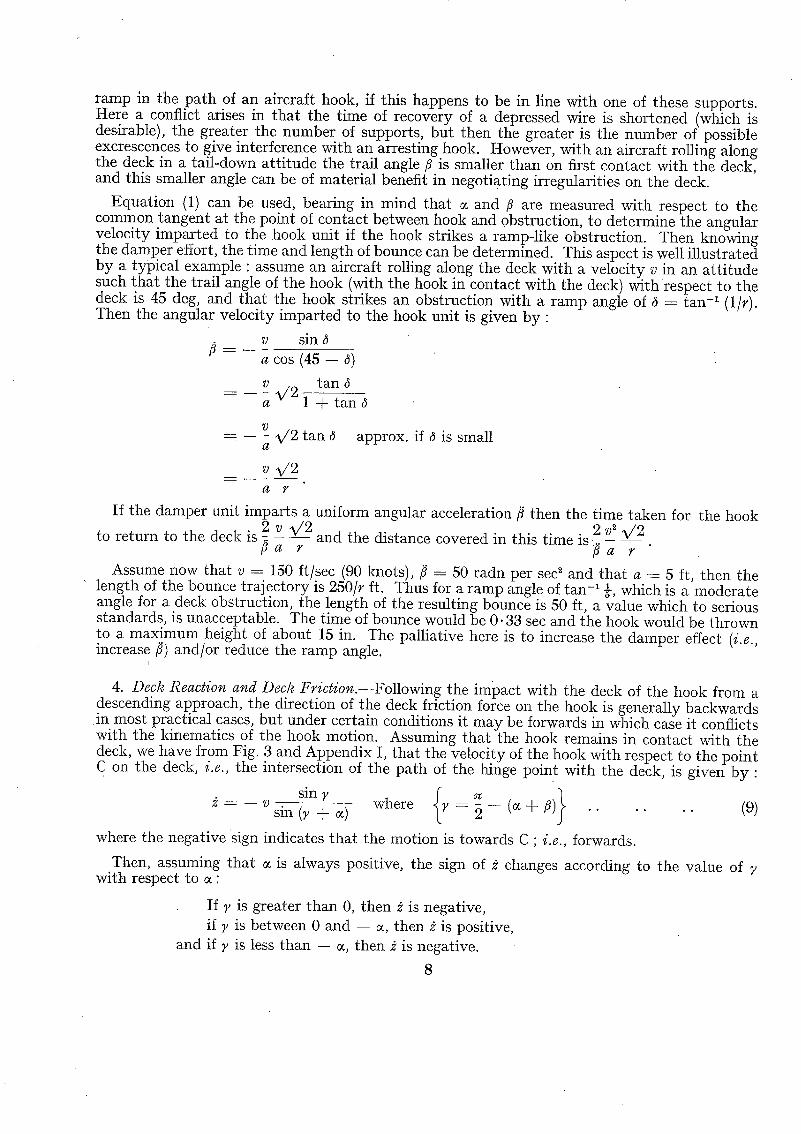
ramp in the pa th of an aircraft hook, if this happens to be in iine with one of these supports. Here a conflict arises in that the time of recovery of a depressed wire is shortened (which is desirable), the greater the number of supports, but then the greater is the number of possible excrescences to give interference with an arresting hook. However, with an aircraft rolling along the deck in a tail-down att i tude the trail angle ~ is smaller than on first contact with the deck, and this smaller angle can be of material benefit in negotiating irregularities on the deck.
Equation (1) can be used, bearing in mind that c~ and fi are measured with respect to the common tangent at the point of contact between hook and obstruction, to determine the angular velocity imparted to the hook unit if the hook strikes a ramp-like obstruction. Then knowing the damper effort, the time and length of bounce can be determined. This aspect is well illustrated by a typical example : assume an aircraft rolling along the deck with a velocity v in an at t i tude such tha t the trail angle of the hook (with the hook in contact with the deck) with respect to the deck is 45 deg, and that the hook strikes an obstruction with a ramp angle of ~ = tan -1 (i/r). Then the angular velocity imparted to the hook unit is given by :
sin a cos (45 -- 6)
_-- _ v %/2 tan a 1 + tan~
7)
a %/2 tan ~ approx, if $ is small
v V 2
If the damper unit imparts a uniform angular acceleration/~ then the time taken for the hook
to return to the deck is 2 v %/2 :. and the distance covered in this time is 2:. v 2 %/2 E a r E a r
Assume now that v ---- 150 ft/sec (90 knots), fi = 50 radn per seal and that a = 5 ft, then the length of the bounce trajectory is 250/r ft. Thus for a ramp angle of tan -1 ~, which is a moderate angle for a deck obstruction, the length of the resulting bounce is 50 ft, a value which to serious standards, is unacceptable. The time of bounce would be 0.33 sec and the hook would be thrown to a maximum height of about 15 in. The palliative here is to increase the damper effect (i.e., increase ~) and/or reduce the ramp angle.
I
4. Deck Reaction and Deck T'riction.--Following the impact with the deck of the hook from a descending approach, the direction of the deck friction force on the hook is generally backwards in most practical cases, but under certain conditions it may be forwards in which case it conflicts with the kinematics of the hook motion. Assuming that the hook remains in contact with the deck, we have from Fig. 3 and Appendix I, that the velocity of the hook with respect to the point C on the deck, i.e., the intersection of the path of the hinge point with the deck, is given by"
sinT v sin (~ + ~) where y = ~ --
indicates that the motion is towards C ; i.e., forwards.
is always positive, the sign of 2 changes according to the value of
where the negative sign
Then, assuming that with respect to ~ :
If ~, is greater than 0, then ~ is negative, if ~, is between 0 and -- ~, then ~ is positive,
and if ~ is less than -- c~, then ~ is negative.
8

Thus when y lies between 0 and -- c~ (i.e.,/7 lies be tween ½= -- c~ and ½=) the hook is t ending to slide backwards, see Fig. 9. Therefore, providing tan -1 ¢ is greater than 0~ + ), (where ~ is the coefficient of friction between hook and deck), then the deck reaction and its accompanying friction force wants to rota te the hook uni t in the opposite sense to tha t prescribed by the kine- matical equat ion (1). The physical in terpre ta t ion of this is tha t under these conditions the hook will t end to jam, as opposed to swinging backwards, be tween the deck and the tail of the aircraft, pu t t ing the hook unit in compression and giving an upward impulsive thrust on the aircraft th rough the hinge point.
Similarly when y is less than -- ~, then if tan -~ # is greater than ~ + 7, j a m m i n g of the hook uni t will occur as before. The configuration of y less t han -- c~ would apply if a forward-facing scoop was employed instead of the more convent ional trailing h o o k - - a proposal as is somet imes made. In such a case/7 would have to be greater than (½= + tan -~ #), and in view of the possibili ty of large values of #, to ensure exceeding this value would involve a very large value of / 7 - cer tainly exceeding ~=.
Summing up, therefore, for convent ional hook installations the trail angle/7 should be less than ½= - - 0~, which is in the same sense as the results of the previous section which indicated tha t /7 should be less than ½= by as large a margin as design considerations will permit.
Consider now the impulsive deck reaction R which is responsible for giving the initial angular veloci ty to the hook unit, the min imu m value of which is given by equat ion (1). In conjunct ion with Fig. 10 let T be the impulsive m o m e n t impar ted by the deck to the hook unit, and R the impuls ive normal reaction between hook and deck ; then :
_ ag cos (/7 - - 4) sec ~ f R dt, w h e r e ~ t a n -~/~ I
v sin c~ also --/7 -- (equation (1))
COS /7
¢ I v sin ¢ cos ;t therefore R dt J g a ~ cos/7 cos (/7 - -~ ) . . . . .
Not ing tha t 2 can only lie between 0 and ½= it follows tha t •
Iv sin ; (a) ! R dt has a m a x i m u m value of- J ga s cos ~/7
(b) f R dt has a m i n i m u m value of 0
when ;t ---- 0
when ~ -- 2
. . (10)
. . ( 1 1 )
(c) Al though ~ can theoretically approach ~ , a more realistic m a x i m u m value i s ~ , in
which case: I v sin ~ 1
f R dthas value of a g a scos ~ 1 + t a n / 7 "
If then t is the durat ion of the impact, the average value of the deck reaction is given by :
R M(K)~vsino~_ 1 .. . . . . . . ( l la ) g t cos ~ $ + # sin/7 cos/7 '
where M/g is t h e mass of the hook uni t and K its radius of gyrat ion about its hinge point.
Unt i l tile value of ~ is known it is not possible to de termine even the average value of R. However it is of interest to find the effect on R of the trail angle /7 and the coefficient of
9
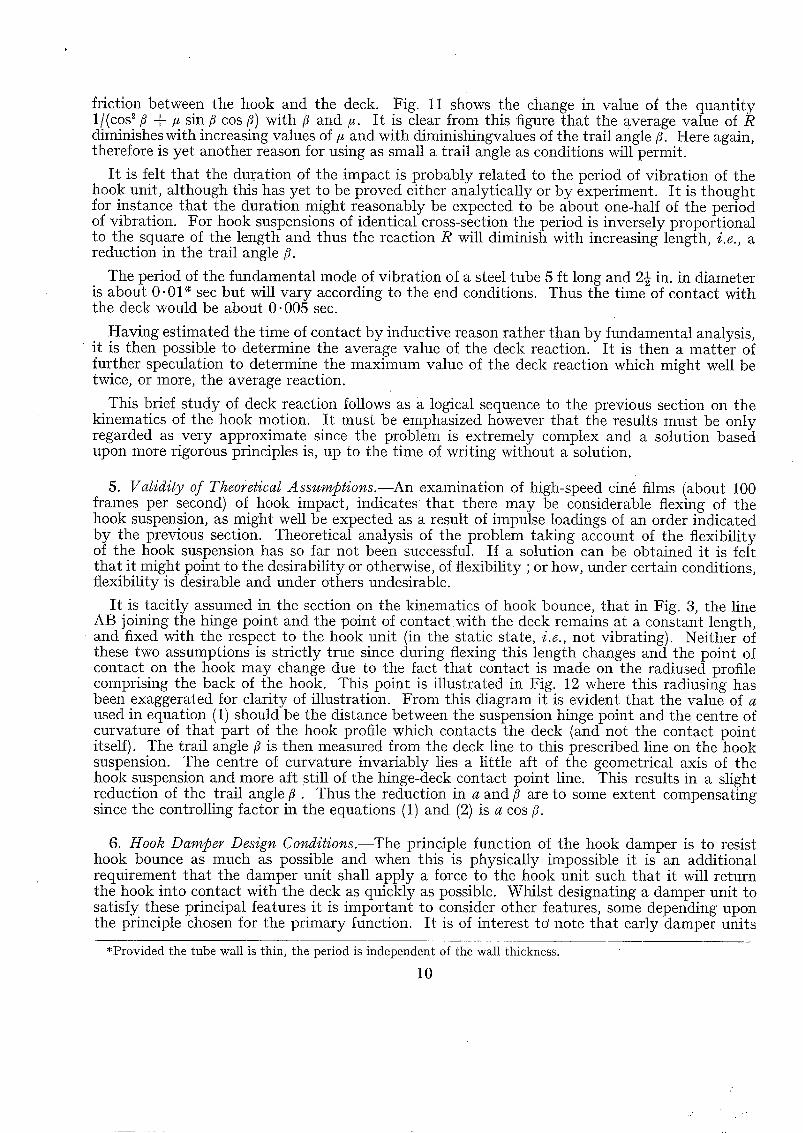
friction between the hook and the deck. Fig. 11 shows the change in value of the quant i ty 1/(cos ~ 3 + /~ sin 3 cos 3) with 3 and/~. I t is clear from this figure that the average value of R diminishes with increasing values of/~ and with diminishingvalues of the trail angle 3- Here again, therefore is yet another reason for using as small a trail angle as conditions will permit.
I t is felt that the duration of the impact is probably related to the period of vibration of the hook unit, although this has yet to be proved either analytically or by experiment. I t is thought for instance that the duration might reasonably be expected to be about one-half of the period of vibration. For hook suspensions of identical cross-section the period is inversely proportional to the square of the length and thus the reaction R will diminish with increasing length, i.e., a reduction in the trail angle 3-
The period of the fundamental mode of vibration of a steel tube 5 ft long and 2½ in. in diameter is about 0 .01" sec but will vary according to the end conditions. Thus the time of contact with the deck would be about 0.005 sec.
Having estimated the time of contact by inductive reason rather than by fundamental analysis, it is then possible to determine the average value of the deck reaction. I t is then a matter of further speculation to determine the maximum value of the deck reaction which might well be twice, or more, the average reaction.
This brief s tudy of deck reaction follows as a logical sequence to the previous section on the kinematics of the hook motion. It must be emphasized however that the results must be only regarded as very approximate since the problem is extremely complex and a solution based upon more rigorous principles is, up to the time of writing without a solution.
5. Validity of Theoi'etical Assumptions.--An examination of high-speed cin6 films (about 100 frames per second) of hook impact, indicates that there may be considerable flexing of the hook suspension, as might well be expected as a result of impulse loadings of an order indicated by the previous section. Theoretical analysis of the problem taking account of the flexibility of the hook suspension has so far not been successful. If a solution can be obtained it is felt that it might point to the desirability or otherwise, of flexibility ; or how, under certain conditions, flexibility is desirable and under others undesirable.
I t is tacitly assumed in the section on the kinematics of hook bounce, that in Fig. 3, the line AB joining the hinge point and the point of con tac twi th the deck remains at a constant length, and fixed with the respect to the hook unit (in the static state, i.e., not vibrating). Neither of these two assumptions is strictly true since during flexing this length changes and the point of contact on the hook may change due to the fact that contact is made on the radiused profile comprising the back of the hook. This point is illustrated in Fig. 19, where this radiusing has been exaggerated for clarity of illustration. From this diagram it is evident that the value of a used in equation (1) should be the distance between the suspension hinge point and the centre of curvature of tha t part of the hook profile which contacts the deck (and not the contact point itself). The trail angle/~ is then measured from the deck line to this prescribed line on the hook suspension. The centre of curvature invariably lies a little aft of the geometrical axis of the hook suspension and more aft still of the hinge-deck contact point line. This results in a s l igh t reduction of the trail angle 3 . Thus the reduction in a and/~ are to some extent compensating since the controlling factor in the equations (1) and (2) is a cos 3.
6. Hook Damper Design Conditions.--The principle function of the hook damper is to resist hook bounce as much as possible and when this is physically impossible it is an additional requirement tha t the damper unit shall apply a force to the hook unit such that it will return the hook into contact with the deck as quickly as possible. Whilst designating a damper unit to satisfy these principal features it is important to consider other features, some depending upon the principle chosen for the primary function. I t is of interest to' note that early damper units
*Provided the tube wall is thin, the period is independent of the wall thickness.
10

(excludlng rubber cord) provided resistance to upswing, but return to the deck depended upon gravity alone. The force exerted by a damper can be developed in several ways or by a com- bination of more than one.
The operation of lowering and raising tile hook is almost invariably now done by a jack unit. This unit is often combined with the bounce control unit which then has three functions to perform, any one of which must not prejudice the other two. Again, following engagement of an arresting wire by a hook, the hook unit may very likely swing up into a near horizontal attitude, a t a more rapid rate* than the upswing resulting from striking tile deck. Under such circum- stances, if the damper forces are generated as a function of the speed of upswing, there may be a danger of excessive resistance in the damper which may result in over-stressing the hook suspen- sion in bending or in bursting the damper unit.
The speed of upswing of a hook following engagement with an arresting wire depends upon : (a) the moment of inertia of the hook unit (b) the physical properties of the rope--line density and elasticity (c) speed of engagement (d) the trail angle of the hook.
To a reasonable approximation, the upswing is that of near critically damped pendulum oscillation. A study of this motion is made in Appendices I I I and IV where it is shewn that the maximum velocity during upswing depends upon the trail angle when the wire is engaged. Here the requirement for trail angle is similar to that to reduce bounce tendencies, i.e., aiming at a value not exceeding some 60 deg.
If it were possible to disengage automatically the damper forces when the arresting rope was picked up, then this would be advantageous but it is doubtful whether this could be realised in practice without undue complications.
It should be unnecessary to emphasize that there should be no slack, either mechanical or fluid, in a hook-damper system and that resistance to bounce should be instantaneously responsive to any tendency to bounce. It will often assist in this respect if the moment arm of the damper unit is not made too small, aiming at a value of say not less than 8 to 10 per cent of the length of tile hook suspension. Tile greater the moment arm the greater becomes the stroke of tile damper jack, but the force required becomes less, which in turn benefits the structure attach- ments. I t is appreciated however that space limitations are often a controlling feature.
A condition which is difficult to satisfy, particularly in certain designs, without adversely effecting other important functions, is that where a hook having been thrown up, is out of range of the deck on its return and its downward motion is stopped by the end limits of the damper iack. A similar condition can arise if due design care is not exercised, when lowering the hook in preparation to land. I t is only rarely that circumstances during landing are such as to give rise to the former condition and it is thus difficult to insist tha t such an event should be catered for. Nevertheless it should be satisfied to as high a degree as possible without prejudice to other functions. However, with the advent of the ' angled ' deck carrier layout, this condition cannot be overlooked even though it presents design difficulties. An aircraft, having failed to engage an arresting wire will often roll off the forward end of the deck in a tail-down attitude, with the hook trailing on tile deck at a relatively small trail angle. As the hook leaves the deck it will, or should be, vigorously thrust down by the damper forces, and its downward motion will be arrested not by the deck but by the end fixings of the damper unit. Here again is a good reason for keeping the moment arm of the damper as large as is reasonably possible.
*As an example : A 5-ft long hook unit with a moment of inertia of 330 lb ft ~ hanging at a trail angle of 60 deg to the pa th of its hinge point, will, when engaging a l{--in, diameter arresting wire at 85 knots, generate a maximum angular velocity of about 25 radians per second compared with an impulsive angular velocity of 8 radians per second when striking the deck with a sinking speed of 20 ft/sec.
11

When the damper holding down force is wholly or in part independent of hook motion (e.g., a pneumatic spring or oleo-pneumatic unit) then after engagement has been made and tile hook suspension i s t ransmitt ing the arresting gear forces to the aircraft, in direction tension, these damper loads also subject the hook suspension to bending loads. Without s u c h bending loads the unit may be designed lighter in weight and hence of reduced moments of inertia, thus requiring a reduced damper load. I t is on the lines of this argument that it is visualised that there may be conditions under which it is impossible to design an installation having the necessary damper force to resist bounce completely ; the strength/weight ratio being the controlling feature.
I t follows from the above that of the design principles tried in practice, the oleo-pneumatic type potentially is the best. Here the air pressure provides a steady downward effort whether the hook is rising or falling, and wtlen rising, the air load is supplemented by hydraulic pressure which is generated by virtue of hook upswing motion but ceases on the downswing. Care must be taken however, that during the downswing there is little or no hydraulic drag. The hydraulic resistance may be generated by displacing fluid through an orifice or through a relief valve. I t should be noted that rarely can an orifice alone be used, but should be protected by a relief valve, which in turn is capable of taking the flow with little rise in pressure above the static cracking value. Again, when fluid is displaced into, say, a reservoir such as an air loaded accumu- lator via a pipe, the bore must be selected in conjunction with the length and maximum speed of flow, otherwise such a pipe line may well act, unintentionally as a restrictor.
The checking of the fall of a hook under the effect of gravity and the down thrust of the damper unit, when this is not done by the hook striking the deck, usually presents a difficult design problem. This action should occupy as short a final increment of the damper stroke as possible, consistent with acceptable end loads on the damper. Where this is done by choking the displacement of hydraulic fluid, as is generally the practice, this should preferably be done through a metered orifice but usually this is impracticable due to the smallness of the dimensions involved. Again this buffering action should be as dead-beat as possible, i.e., there should be no bounce action on the end stops. Difficulties that have been encountered suggest that it may be preferable to incorporate this buffer action outside the damper unit by yielding at tachments between either the damper unit and the hook suspension or between the damper unit and its a t tachment to the aircraft structure.
There is yet another condition which should be examined in damper and hook installation design. If an aircraft makes a low approach, so low that the hook suspension (not the hook) strikes tile combing of the round-down then the hook unit is su.bjected to an impulsive blow which will generate high angular velocities, a formula for which is developed in Appendix II. I t is not a necessity that the hook shall not bounce under these conditions but it is obviously essential that the rapid closure of the damper, as under conditions immediately following engage- ment of a wire, shall not damage the damper and so prejudice the chances of engaging an arresting wire when these are reached about one second of time later.
The geometry of the damper at tachment to the hook suspension should be such that the moment arm is of as uniform a value as possible throughout the full travel of the hook suspension, or more precisely, the moment of damper force about tile suspension hinge point should be as uniform as possible.
Finally, a plea is made for simplicity of design with due regard for ease of servicing, main- tenance and inspection, bearing in mind tha t with the aircraft in a static attitude, whether it be a nose-wheel or a tail-wheel layout, the hook in the ' down ' position is not at the limit of its travel, particularly with a tail-wheel aircraft.
7. Testing of Dampers.--The testing of a damper's ability to control bounce cannot be regarded as being particularly well-developed at present. This is due mainly to the difficulty of producing a rig which will reproduce the several principal conditions wi th which a damper has to cope.
12
Manual manipulation of the hook unit, in the ' down ' position, can under certain circumstances give an indication of the damper's effectiveness, but where resistance is a function of speed of upswing it is not possible to reproduce (manually) representative upswing speeds.
During arresting proof strength testing, when the aircraft is taxied at speed into an arresting gear (on a land installation), an indication of the effectiveness of the damper can be seen during the taxying run with the hook down. However, under these conditions it is usually not possible to get the hook into its fully down position, since the wheels must be clear of the deck or ground to achieve this.
Visual observation during deck landings, if necessary supplemented by high-speed cin6 records, is useful but can only indicate roughly the order of effectiveness. I t must be appreciated, too, that an assessment of the damper performance is required before this stage is reached.
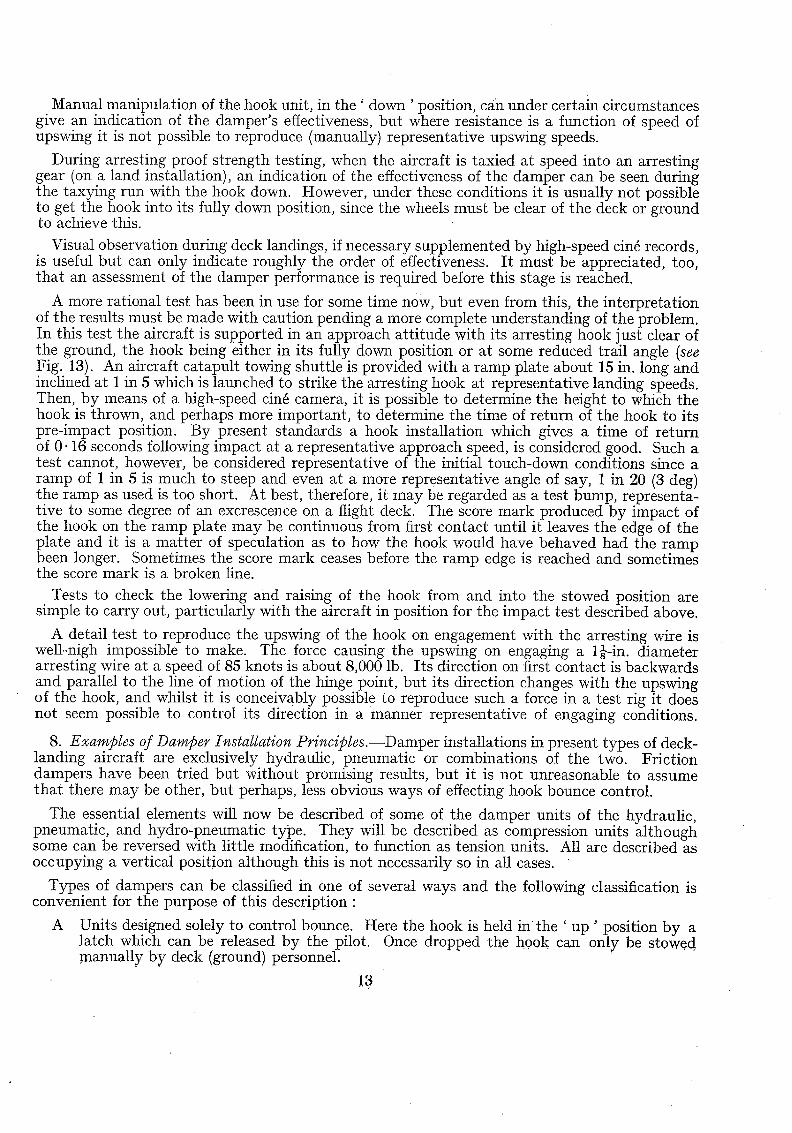
A more rational test has been in use for some time now, but even from this, the interpretation of the results must be made with caution pending a more complete understanding of the problem. In this test the aircraft is supported in an approach att i tude with its arresting hook just clear of the ground, the hook being either in its fully down position or at some reduced trail angle (see Fig. 13). An aircraft catapult towing shuttle is provided with a ramp plate about 15 in. long and inclined at 1 in 5 which is launched to strike the arresting hook at representative landing speeds. Then, by means of a high-speed cin6 camera, it is possible to determine the height to which the hook is thrown, and perhaps more important, to determine the time of return of the hook to its pre-impact position. By present standards a hook installation which gives a time of return of 0.16 seconds following impact at a representative approach speed, is considered good. Such a test cannot, however, be considered representative of the initial touch-down conditions since a ramp of 1 in 5 is much to steep and even at a more representative angle of say, 1 in 20 (3 deg) the ramp as used is too short. At best, therefore, it may be regarded as a test bump, representa- tive to some degree of an excrescence on a flight deck. The score mark produced by impact of the hook on the ramp plate may be continuous from first contact until it leaves the edge of the plate and it is a matter of speculation as to how the hook would have behaved had the ramp been longer. Sometimes the score mark ceases before the ramp edge is reached and sometimes the score mark is a broken line.
Tests to check the lowering and raising of the hook from and into the stowed position are simple to carry out, particularly with the aircraft in position for the impact test described above.
A detail test to reproduce the upswing of the hook on engagement with the arresting wire is well-nigh impossible to make. The force causing the upswing on engaging a 1}-in. diameter arresting wire at a speed of 85 knots is about 8,000 lb. Its direction on first contact is backwards and parallel to the line Of motion of the hinge point, but its direction changes with the upswing of the hook, and whilst it is conceivably possibl e to reproduce such a force in a test rig it does not seem possible to control its direction in a manner representative of engaging conditions.
8. Examples of Damper Installation Principles.--Damper installations in present types of deck- landing aircraft are exclusively hydraulic, pneumatic or combinations of the two. Friction dampers have been tried but without promising results, but it is not unreasonable to assume tha t there may be other, but perhaps, less obvious ways of effecting hook bounce control.
The essential elements will now be described of some of the damper units of the hydraulic, pneumatic, and hydro-pneumatic type. They will be described as compression units al though some can be reversed with little modification, to function as tension units. All are described as occupying a vertical position although this is not necessarily so in all cases.
Types of dampers can be classified in one of several ways and the following classification is convenient for the purpose of this description :
A Units designed solely to control bounce. Here the hook is held in the ' up ' position by a latch which can be released by the pilot. Once dropped the hook can only be stowed manually by deck (ground) personnel.
13
B Units designed solely to control bounce together with facilities whereby the aircraft hydraulic system is used to raise the hook (when airborne or on the ground) under the control of the pilot.
C Units which employ the main aircraft hydraulic system for providing the hook bounce resisting effort and the same source of power for raising the hook under the control of the pilot.
It is preferred that the hook can be raised by a pilot-operated control without the need of manual assistance by deck personnel, since this can speed up the landing cycle time of deck- landing aircraft.
Units in class A and B will continue to function in their control of bounce if the aircraft hydraulic supply has failed, whereas with class C units bounce control may be lost with loss of main hydraulic pressure, or at best some damping may be obtained but diminishing with each succeeding bounce.
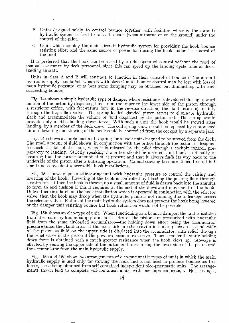
Fig. 14a shows a simple hydraulic type of damper where resistance is developed during upward motion of the piston by displacing fluid from the upper to the lower side of the piston through a restrictor orifice, with free-return flow in the reverse direction, the fluid returning mainly through the large flap valve. The spring-loaded glanded piston serves to eliminate hydraulic slack and accommodates the volume of fluid displaced by the piston rod. The spring would provide only a little holding down force. With such a unit the hook would be stowed after landing, by a member of the deck crew. The coil spring shown could be replaced by compressed air and lowering and stowing of the hook could be controlled from the cockpit by a separate jack.
Fig. 14b shows a simple pneumatic spring for a hook unit designed to be stowed from the deck. The small amount of fluid shown, in conjunction with the orifice through the piston, is designed to check the fall of the hook, when it is released by the pilot through a cockpit control, pre- paratory to landing. Strictly speaking the orifice should be metered, and there is difficulty ill ensuring that the correct amount of oil is present and that it always finds its way back to the underside of the piston after a buffering operation. Manual stowing becomes difficult on all but small and conveniently accessible hook installations.
Fig. 15a shows a pneumatic-spring unit with hydraulic pressure to control the raising and lowering of the hook. Lowering of the hook is controlled by bleeding the jacking fluid through a restrictor. If then the hook is thrown up a small amount of fluid is drawn back into the annulus to form an end cushion if this is required at the end of the downward movement of the hook. Unless there is a latch on tile hook installation which is operated in conjunction with the selector valve, then the hook may droop when tile hydraulic pump is not running, due to leakage across the selector valve. Failure of the main hydraulic system does not prevent the hook being lowered or the damper unit resisting bounce but hook retraction would not be possible.
Fig. 15b shows an oleo-type of unit. When functioning as a bounce damper, the unit is isolated from the main hydraulic supply and both sides of the piston are pressurised with hydraulic fluid from tile same air-loaded accumulator-- the holding down effort being the accumulator pressure times the gland area. If the hook kicks up then cavitation takes place on the underside of the piston as fluid on the upper side is displaced into the accumulator, with relief through the relief valve in the piston if the pressure becomes excessive. Thus a moderate static holding down force is obtained with a much greater resistance when the hook kicks up. Stowage is effected by venting the upper side of the piston and pressurising the lower side of the piston and the accumulator from the main hydraulic supply.
Figs. 15c and 15d show two arrangements of oleo-pneumatic types of units in which the main hydraulic supply is used only for stowing the hook and is not used to produce bounce control forces, these being obtained from self-contained independent oleo-pneumatic units. The arrange- ments ShOWn lead t.o complete self-contained units, with one pipe connecti011.. Not havin 6 a

separate accumulator leads to a more bulky unit, but nevertheless the arrangement has good potential practical advantages, such as the fact that the unit can be removed for servicing or replacement by the removal of the two main fixing pins. Also, pipe runs to a separate accumu- lator, with the extra pressure joints and fixing arrangements, are avoided.
Fig. 16a shows a purely hydraulic unit where either the upper or lower side of the jack piston is pressurised, from aircraft hydraulics via a selector valve, to give resistance to bounce or stowage of the hook respectively. I f the hook kicks up then the fluid is displaced from the upper to the lower side of the piston through a relief valve mounted externally on the unit body. By this means the need to force the displaced fluid back along a long pipe, which would act as a restrictor, to the main hydraulic accumulator is avoided. Adjustable restrictors on the two hydraulic lines can be adjusted to give various characteristics (within limits) ; the one in the line to the underside, in particular, giving a measure of buffer control. Failure of the main hydraulic supply will put this damper unit out of action apart from an ability to lower the hook.
Fig. 16b shows another arrangement in which the main aircraft hydraulic supply is used to provide bounce control and provide the hook stowage effort. Both sides of the piston are pressurised with hydraulic fluid for bounce control. When the hook kicks up, the fluid displaced by the piston is accommodated in a small air-loaded accumulator and due to the restricted flow to the underside of the jack piston there is a tendency to cavitation with a result that the bounce control force is that on the upper side of the piston without any relief due to pressure loads on the underside of the piston. A relief valve might well be fitted (but not shown in Fig. 16b) across the two piston faces.
Hook stowage is effected by maintaining hydraulic pressure on the lower piston face and venting the upper side to the main header tank.
9. Effect of Pipe Line and Orifice Size in Hydraulic Damper Units.--Reference has been made previously to the critical influence of the size of orifice and relief valves, and the pipe sizes where the latter are employed to carry hydraulic fluid, displaced during bounce control, to a separate accumulator.
Considering the case of the pressure drop along a pipe run :
Let ~ be the angular velocity of the hook suspension
L the moment arm of the damper unit
D the effective bore of the damper unit
l the length of the pipe run
d the bore of the pipe run
e the density of the hydraulic fluid
f coefficient of fluid friction.
If the closing velocity of damper unit = EL, then the velocity of fluid in pipe = (D/d)~l~L and the pressure drop along pipe (using the well-known formula*
4flY2( 4 f lv~ ) 4 flD~l~L ~ 2gd in the f o r m ~ = # --
---- 4 f ~ (fiL) 2 . . . . . (13)
Geometrical details may modify the above simple argument bu t does not alter the generalisation.
*The familiar form 4fly2/2 gd for loss of head is fundamentally 4flv~/@d (it being a convenient co!ncl_'dent, 2~ approximatel.y equals ~ in t.he c.ase of water). Hence the pressure drop is -4 flv~/d,
5
th.at

From equation (13) it is clear that the pressure required to drive the fluid along the pipe varies as the fifth power of the pipe bore, e.g., changing the bore from 0.25 in. to 0.1 in. will increase the pressure one hundredfold.
Again, using the example given as a footnote ill section 6 if the pipe is just adequate for bounce control at, say, 8 radn per second, then if on engagement of the arresting wire the hook suspension generates 25 radn per second, the pressure to drive the fluid along the pipe will increase tenfold.
A similar simple argument can be used in respect of hydraulic fluid flow through the damping orifice. With the same nomenclature as before, except that d is now the diameter of the orifice, and assuming that v is the velocity of hydraulic fluid through the orifice, we have :
Change of pressure (p) across the orifice -- O v2 2g Then we have the fact that the displacement of fluid by the damper equals the displacement
through the orifice, i.e.,
Therefore P = (ilL)2 2g . . . . . . .
Thus the pressure developed is very sensitive to the orifice size, i.e., the fourth power of its diameter.
From equation (14) it follows that :
0
If the orifice is adequate to control bounce of 8 radn per second, then if 25 radn per second is generated as a result of engaging an arresting wire, the pressure will increase tenfold unless the orifice is supplemented with a relief value. Such a relief valve in addition to cracking at the designed pressure, must (together with the orifice area) provide a portage area of at least three times the orifice area.
These two simplified studies illustrate the special need for care in the design of orifices, relief valves and pipe connections. Any particular design will require careful consideration of the details around these particular points. The actual size of an orifice will depend upon its location and formation, i.e., whether it is approached through a passage and whether it is shaped to give a coefficient of contraction approaching unity or some lesser value. Likewise the portage area of a relief valve must be designed with due consideration for hydraulic losses which in turn will depend upon design details. In the case of a pipe connection, in addition to friction losses already mentioned where will be losses at entry' to the pipe, particularly if this is not bell-mouthed, losses at elbows, and on discharge into the accumulator.
10. Further Investigation. The present study of the hook bounce problem is by no means complete and the following investigations are necessary in order to extend present knowledge of the subject :
(a) An examination of existing hook installations should be made in the fight of the present kinematical theory.
(b) An investigation should be made to establish how fa r it is practical to apply fully the implications of the kinematical theory. I t may, for instance, be impractical, on account of strength/weight ratio limitations, to apply the necessary damper forces to resist bounce com- pletely ; especially at high sinldng speeds. If this is so, then what is the least bounce obtainable w~thin reasonable strength limits ? To this end a study should be made of the choice of section
.6
of the hook suspension : e.g., Solid circular, .circular tube, or some other section. A cautioning note is included here to the effect that the contribution (if any) of flexibility may influence any findings on this account.
(c) An analytical investigation is required of the problem taking due account of the flexibility of the hook suspension. Attempts on these lines have so far not been very fruitful.
(d) As an aid to (c) above it is recommended that very-high-speed cinfi records (say 1,000 frames per second) be taken of tests employing the ' catapulted ramp ' technique. Such tests should be commenced using only the hook suspension (without hook), using various materials and sections, using various trail angles, and with and without a damper unit. Finally, such tests as these should be carried out with the hook attached to the suspension.
(e) An investigation of the ' catapulted ramp' technique should be carried out to establish the effect of Changes of ramp angle and ramp length, and to establish more precisely what information such a test gives, and the interpretation of this information in the assessment of a hook installa- tion for deck landing.
( f ) An investigation is required into high-speed flow of hydraulic fluid through pipes and orifices such as are employed in present "damper units.
(g) Design studies should be made with the object of satisfying as completely as possible all the essential requirements of a hook instal lat ion--part icularly the damper un i t - - and the most promising schemes manufactured and tested on representative high-landing-speed aircraft.
On the question of design it is for consideration, for instance, whether the conventional rigid vee or shaft-type hook suspension can be improved upon, although in this respect the present simplicity has much in its favour. There may be advantages in bounce control if the conventional suspension had a traverse joint part way down (with suitable limit stops and damper) the upper portion lying at large trail angle and the lower portion at small.angle. Such a scheme presents difficulties in the case of landing in a tail-down atti tude but has attractive features if engagement with an arresting wire were delayed until the aircraft was rolling on all three wheels (assuming a nose-wheel layout) as is envisaged in operation on runways.
(h) Since hook bounce depends both on the hook installation and the nature, particularly the profile, of the landing surface; adequate consideration should be given to both features. Whilst recognising that deck landing lights and arresting-wire rope supports are necessary, no effort should be spared to ensure that such potential obstructions are both a minimum in number and in the ramp angle that they present to the hook. No minimum ramp angle can be stated and satisfaction cannot be assured until this is zero. Therefore the design and the case for the necessity of any potential obstructions in the landing area should be kept under constant review.
11. Conc lus ions .~Wi th the ever increasing approach speeds of successive generations of deck landing aircraft and in consequence of this, the reduced area of touch-down following on which satisfactory arrested landing can be made, it is imperative tha t arresting hook bounce shall be reduced to an absolute minimum in order to insure engagement with an arresting wire within this limited area. A critical and searching examination of the hook bounce problem shews gaps in the knowledge of the fundamentals of the problem.
The probable use of arresting gears on airfields again makes it essential that the understanding of the hook bounce problem shall be developed to as high a standard as possible.
Two clear-cut conclusions emerge from the present study, namely, that the trail angle of the hook should be as small as is reasonably possible, certainly not more than 65 deg if possible, and that the surface of the touch-down area shall be free from obstructions. Both these factors have become self evident in a qualitative manner, particularly the latter, from experience during the past years, and the present study, it is considered, enables quantitative values to be estab- lished for the purpose of design and general assessment. The study also demonstrates that even though the above two conditions are met to a high degree, the absence of bounce can only be assured if h igh damper loads are employed.
No conclusions are submitted here concerning the effect of the flexibility of the hook suspension.
17
#
:g
0
/3
1, =
61
C
d
d
d
D
D , E , F
f g
h
H
I k
K
k
LIST OF SYMBOLS
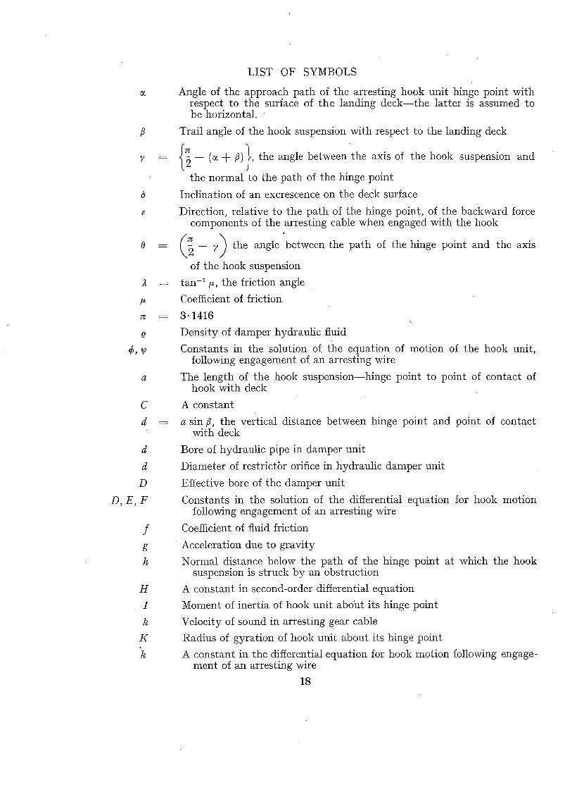
Angle of the approach path of the arresting hook unit hinge point with respect to the surface of tile landing deck--the latter is assumed to be horizontal.
Trail angle of the hook suspension with respect to the landing deck
~2-- (0~+/3)~ , the angle between the axis of the hook suspension and K . /
the normal to the path of the hinge point
Inclination of an excrescence on the deck surface
Direction, relative to the path of the hinge point, of the backward force components of the arresting cable when engaged with tile hook
I "
( 2 -- ;~) the angle between tile path of the hinge point and the axis % .
of tile hook suspension
tan -1/~, the friction angle
Coefficient of friction
3"1416 \ ,
Density of damper hydraulic fluid
Constants in the solution of the equation of motion of the hook unit, following engagement of an arresting wire
The length of the hook suspension--hinge point to point of contact of hook with deck
A constant
a sin/3, tile vertical distance between hinge point and point of contact with deck
Bore of hydraulic pipe in damper unit
Diameter of restrict6r orifice in hydraulic damper unit
Effective bore of the damper unit
Constants in the solution of the differential equation for hook motion _ following engagement of an arresting wire
Coefficient of fluid friction
' Acceleration due to gravity
Normal distance below the path of the hinge point at which the hook suspension is struck by an obstruction
A constant in second-order differential equation
Moment of inertia of hook unit aboiit its hinge point
Velocity of sound in arresting gear cable
Radius of gyration of hook unit about its hinge point
A constant in the differential equation for hook motion following engage- ment of an arresting wire
18
LIST OF SYMBOLS- -con t inued
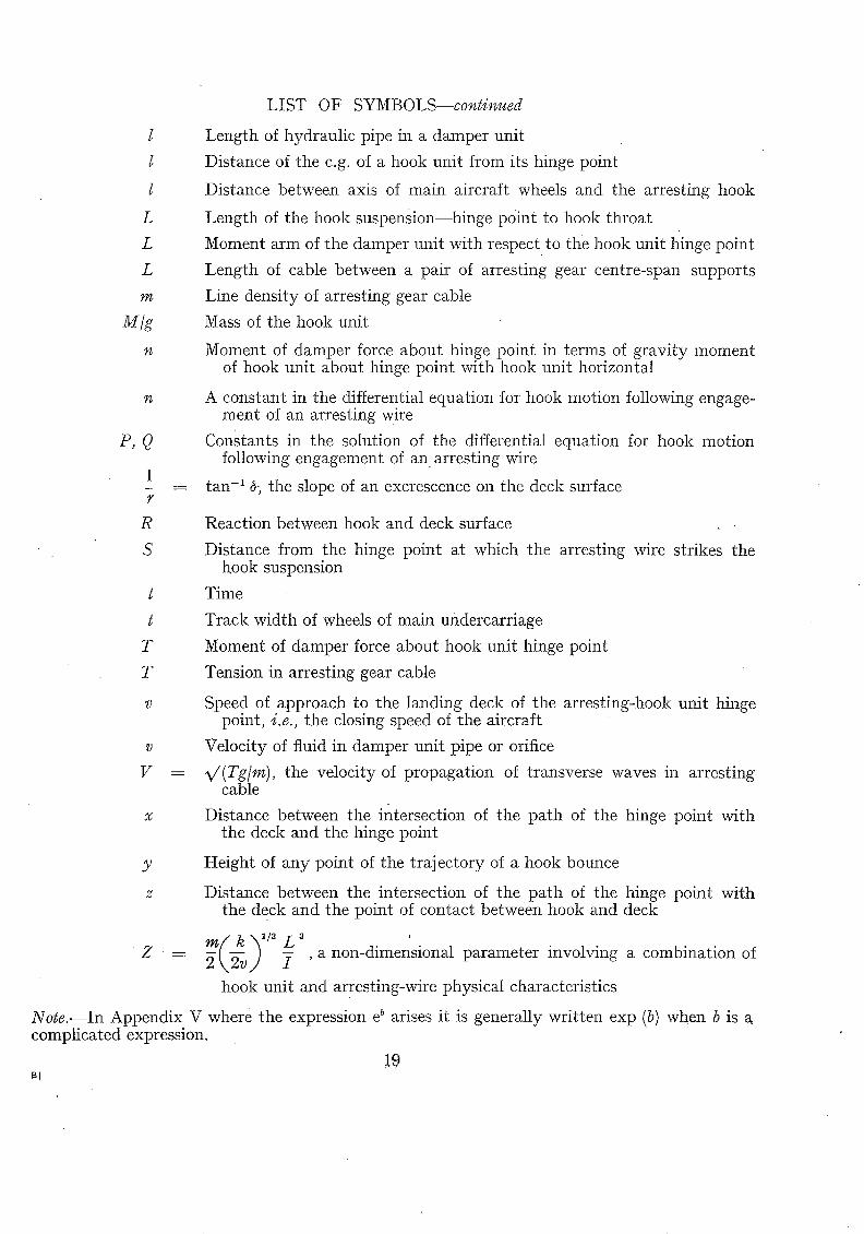
l
L
L
L
M/g
~4
Length of hydraulic pipe in a damper unit
Distance of the c.g. of a hook unit from its hinge point
Distance between axis of main aircraft wheels and the arresting hook
Length of the hook suspension--hinge point to hook throat
Moment arm of the damper unit with respect to the hook unit hinge point
Length of cable between a pair of arresting gear centre-span supports
Line density of arresting gear cable
Mass of the hook unit
Moment of damper force about hinge point in terms of gravity moment of hook unit about hinge point with hook unit horizontal
P,Q
~¢ A constant in the differential equation for hook motion following engage- ment of an arresting wire
Constants in the solution of the differential equation for hook motion following engagement of a n arresting wire
1 - = tan -1 d; the slope of an excrescence on the deck surface
R Reaction between hook and deck surface
S
t
t
T
T
Distance from the hinge point at which the arresting wire strikes the hook suspension
Time
Track width of wheels of main undercarriage
Moment of damper force about hook unit hinge point
Tension in arresting gear cable
v Speed of approach to the landing deck of the arresting-hook unit hinge point, i.e., the closing speed of the aircraft
v Velocity of fluid in damper unit pipe or orifice
V = v ' (Tg/m) , the velocity of propagation of transverse waves in arresting cable
x Distance between the intersection of the path of the hinge point with the deck and the hinge point
Y Height of any point of the trajectory of a hook bounce
Distance between the intersection of the path of the hinge point with the deck and the point of contact between hook and deck
m~ k ~/~ L 3 Z = 2-~,2vfl I , a non-dimensional parameter involving a combination of
hook unit and arresting-wire physical characteristics
Note . - - In Appendix V where the expression e b arises it is generally written exp (b) when b is complicated expression.
!9 N
No. Author
1 D. Pierce . . . .
2 N . I . Bullen
R E F E R E N C E S
Title, etc.
Note on the bounce characteristics and anti-bounce requirements for Naval aircraft arrester hook suspensions. R.A.E. Catapult Section Note 60. October, 1944.
Behaviour of supported length of arresting gear rope under impact from wheel. R.A.E. Tech. Note NA.183. A.R.C. 12,143. August, 1948.
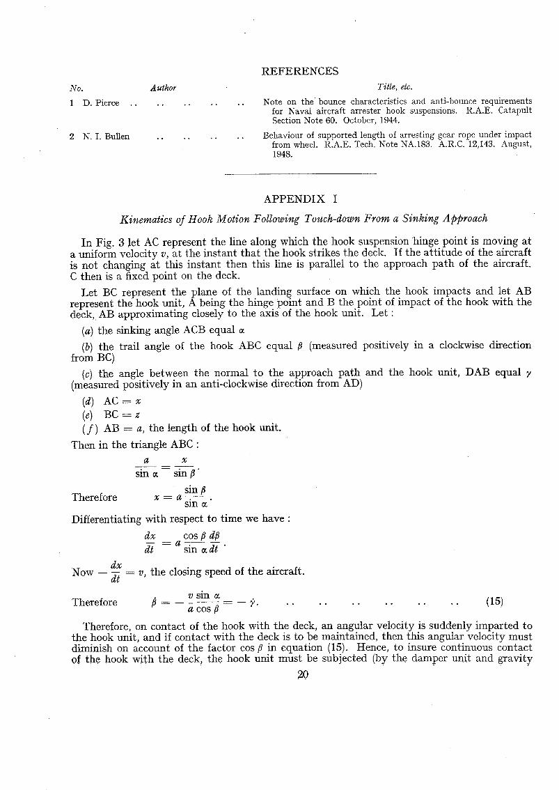
A P P E N D I X I
Kinematics of Hook Motion Following Touch-down From a Sinking Approach
In Fig. 3 let AC represent the line along which the hook suspension hinge point is moving at a uniform velocity v, at the instant that the hook strikes the deck. If the at t i tude of the aircraft is not changing at this instant then this line is parallel to the approach path of the aircraft. C then is a fixed point on the deck.
Let BC represent the plane of the landing surface on which the hook impacts and let AB represent the hook unit, A being the hinge point and B the point of impact of the hook with the deck, AB approximating closely to the axis of the hook unit. Let •
(a) the sinking angle ACB equal
(b) the trail angle of the hook ABC equal /~ (measured positively in a clockwise direction from BC)
(c) the angle between the normal to tile approach path and the hook unit, DAB equal (measured positively in an anti-clockwise direction from AD)
(d) AC-=- x (e) BC = z ( f ) AB =- a, the length of the hook unit.
Then in the triangle ABC • a x
sin ~ sin
sin Therefore x -= a .
s in 0¢
Differentiating with respect to time we have •
dx cos/~ d/~ - - a
dt sin ~ dt "
dx Now -- d-t = v, the closing speed of the aircraft.
v s in Therefore /t -- a cos/~ -- p . . . . . . . . . . . . . (15)
Therefore, on contact of the hook with the deck, an angular velocity is suddenly imparted to the hook unit, and if contact with the deck is to be maintained, then this angular velocity must diminish on account of the factor cos fl in equation (15). Hence, to insure continuous contact of the hook with the deck, the hook unit must be subjected (by the damper unit and gravity

forces) to an angular acceleration. with respect to t ime • i.e.,
p _
This acceleration is obtained by differentiating equat ion (15)
- - -- - s m o~ sec/~ tan ~ . a
= ( v sin c~) ~ sec2 ~ tan ~
_-- ~2 tan ~ . . . . . . . . . . . . . . . . . (16)
It follows therefore tha t with the reduct ion in trail angle ~ which follows the initial impact of the hook wi th the deck, the values of -- # and/~ diminish, as shown by the two curves above the line AC in Fig. 3, approaching zero as the trail angle approaches zero.
Again, in the triangle ABC • a z
- - •
sin ~ sin ,~ + ),
COS y Therefore z = a -
sin ~"
Differentiating with respect to t ime we have •
dz sin y . dt -- a sin c~ r
sin r v sin c~ sin c~ a cos
sin COS
sin 7 = -- Vsin (r + ~) . . . . . . . . . . . . . (17)
Now -- 2 equals the veloci ty with which the hook impact ing point is approaching the fixed point C on the deck, so t ha t if -- 2 is positive the mot ion of the hook is towards C and if negat ive it is away from C, i.e. backwards. Thus for values of r between 0 and -- c~ the mot ion of the hook is backwards with respect to the deck, whilst for all o ther values of 7, the mot ion is forwards. This direction of mot ion of hook relative to the deck determines the direction of the friction forces b e t w e e n hook and deck (see Fig. 9). Thus in the case where y has values between 0 and -- c~, the friction forces t end to swing the hook forward and the kinematical equat ions prescribe backward motion. The physical in terpre ta t ion of this conflict is tha t the hook suspension is subjected to a j amming action between the deck and the hinge pin on the aircraft, if c~ + (-- ~) is less than the friction angle t an -! ~.
A P P E N D I X II
Kinematics of Hook Motion Following Impact on the Hook Suspension
T h e conditions to be invest igated here are those which occur when an aircraft makes a too low approach and the hook suspension strikes the ' round-down ' of the flight deck.
In Fig. 17 let AB represent the hook uni t approaching the deck along a line AC at a velocity v. Assume tha t impact occurs at a point E which is a normal distance h from the approach Iine of the hinge point, and tha t the suspension lies at an angle 0 with respect to the approach line~ i.e., 0 ---- Po + ~,
2 !

Then, in the triangle A oED
A oD = x = h cot 0 .
Differentiating with respect to time we have :
dx -- h cosec ~ 0. O.
dt
Now dx/dt = v, the closing speed of the aircraft.
Therefore 6 v = - - ~ s i n 2 0 . . . . . . .
Differentiating again with respect to time :
v = -- ~ 2 s i n 0 cos 0.0
. . . . . . . . . . ( i s )
= 2 sin s 0 cos 0 . . . . . . . . . . . . . . . (19)
is therefore, by differentiating sin 3 0 cos 0 with respect to 0 and equating to zero, a maximum when 0 equals ~/3 (60 deg), a value likely to be used in practice.
Fortunately there is no requirement that the hook suspension shall not bounce following impact on the round-down, otherwise the angular acceleration to be produced by the damper forces, as given by equation (19), would be excessive. It is however a requirement that the striking of the round-down and the consequent angular velocity, given by equation (18), shall not damage the damper unit. The angular velocity generated under these conditions is far in excess of those given by equation (1) and are of an order, assuming that h is a large fraction of the length of the hook suspension, similar to those generated following engagement with an arresting wire.
A P P E N D I X II I
The Motion of an Arresting Hook Immediately After Engaging an Arresting Wire
The motion on the hook unit following engagement of an arresting wire is required for design purposes for two main reasons. First to determine the maximum rate of closure of the hook damper unit, and to establish the uppermost position in order to avoid the hook striking the aircraft structure, or where this is permitted, to determine the impacting velocity.
When a point on a straight flexible elastic cable (which is initially free of tension) is suddenly moved at a uniform speed in a straight line normal to the cable, it is possible to determine the tension in the cable and the angle that the cable takes up on either side of the point of impact (see Fig. 18):
(a) Cable tension
(b) Cable angle with respect to original line of cable, adjacent to the point of impact and therefore
(c) Backward force at point of impact
g
~ 2US~ 3 m_ g
2 2
where v is the ve.locity of the impact point with respect to original condition of the cable
k is the velocity of sound in the cable
m is the line density of the cable.
N o t e . - - ' Backward ' is interpreted literally, i.e., in the opposite direction to which the point of impact is moving at any particular instant.
I t is to be further noted that the tension, angle and force formula above assume that the cable is initially free of tension. This is not so in an arresting gear but the initial tension is so small in terms of the impact tension that the former can be neglected for the purpose of this analysis of ' upswing '.
I t is considered that the theory on which this is based is sufficiently flexible to be applicable without serious error even if the impact velocity is not constant and not in a straight lille (but in a plane which is normal to the original line of the cable). When a point in the arresting wire is impulsively carried forward by an engaging arresting hook, the backward force component of the cable tension swings the hook unit up into a near horizontal position. Under conventional arresting conditions the time of upswing is a fraction of a second (of the order of 0- 1 sec) during which time the impact tension and the angle of the cable at the hook will not change significantly. A fraction of a second later the cable tension and the cable angle at the hook will increase rapidly to develop the maximum arresting effort, by which time the upswing of the hook is completed.
Consider first the case where the hook throat engages directly with the arresting wire, i.e., the rope does not first strike the hook suspension a little way above the hook and then slide down into the hook throat.
In Fig. 19 let AB represent a hook unit, the hinge point A of which is moving with a uniform velocity in straight line.
Let L be the length from the hinge point to the hook throat
l the distance of the c.g. of the hook unit from the hinge point
M/g the mass of the hook unit
I moment of inertia of the hook unit about the hinge point
T the moment of the damper force about the hinge point, resisting upswing
m the line density of the arresting wire
k the velocity of sound in the arresting wire
v the uniform velocity of the hinge point
0 the trail angle of the hook suspension with respect to the path of the hinge point
a n g l e of path of hinge point with respect to the horizontal.
I t should be noted that initially, both 6 and 0 are negative.
Then the velocity of the hook parallel to the line of motion of the hinge point
---- v + L sin O. 0
and the velocity of the hook normal to the line of motion of the hinge point
-- L cos 0.6.
Therefore the absolute velocity of the hook
= [(v + L sin 0.6) ~ + (L cos 0.6)~] 1/~
-~ Iv ~ + 2vL sin O. 0 + L~O~] ~/~,
23
in a direction relat ive to the pa th of the hinge point o f :
-- L cos 0 . 6 = tan -1
v + L sin O .0
-- L cos 0 . O therefore sin e = (v ~ + 2vL sin 0 . O + L~O~) 1/~
v -¢- L s in 0 . 0 and cos e =
(v ~ + 2vL sin 0 . 0 + L~O~)~/~"
We know therefore tile absolute velocity of the hook and its direction, ~. Therefore t h e force on the hook due to impact with the cable is :
2(v 2 + 2vL sin 0 . 6 + L~O~) '/6 _m g
Resolving this into components normal to, and parallel to the pa th of the hinge point, and then taking moments about the hinge point, we obtain the equat ion of mot ion of the hook uni t :
2(v ~ + 2vL sin 0 . 0 + L20~)5/6 g [L cos e sin 0 -- L sin e cos 0]
Z., - - M t c o s ( O - - ~ ) - - T = - - - 0 .
g
Therefore 2(v ~ + 2vL s i n 0 . 0 + L~02)l/3 ( ~ ) 1/3m (vL s in0 + L~6)
I . . - - M l c o s ( O - - c ~ ) - - T = - - - O . . . . . . . . . . . (20)
g
The solution of this equat ion is most convenient ly obtained by a step-by-step process. W h e n t = 0 (the ins tant of engagement of hook wi th the wire) 0 = 0 and 0 = Oo, the trail ~mgle prior to impact. Hence 0 is determined, i.e.,
2v s/3 sin 0 MI cos (0 -- c~) -- T -- 6. \ 2 2 g g
Assuming tha t this value of 0 is constant for a small increment of time, then the value of O and 0 at the end of the t ime increment can be determined. Wi th these values of 0 and 0 a new value for 0 can be computed and will be assumed constant for the subsequent small increment of time. The process is carried on, using sufficiently small intervals of t ime, unt i l 0 is again zero, and the corresponding value for 0 represents the highest position tha t the hook uni t will reach, providing the hook or arresting wire has not at any stage been s topped by the aircraft s tructure (e.g., the tail booms in the case of the Sea Vampire). The highest point reached will be on a line close to the pa th of the hinge point. It will be shown in Appendix IV tha t by simple approxima- tions, equations (20) can be reduced to one corresponding to an oscillatory mot ion with veloci ty damping, and how in the case of convent ional hook installations and arresting gears the hook uni ts are roughly critically damped.
Usually the two terms Ml cos (0 - - c~) and T can be neglected except at very low engaging speeds, wi thout serious effect on the predicted motion. Their ommission will increase slightly bo th the m a x i m u m angular velocity and in some cases the height of the m a x i m u m upswing.
Consider now the case where the arresting wire first strikes the hook suspension before sliding down it and into the throat of the hook. During this brief period the rope is depressed and s imultaneously the hook unit is given an upward motion. Fig. 20 is an exaggerated diagram of this condition, the position of the initial impact being shown much higher up the hook suspen- sion than would normal ly occur in general practice.
24
if friction between the rope and the hook suspension is neglected then the rope will be depressed in a direction normal to the hook suspension with a velocity (v sin 0 + S$) and will slide down the hook suspension with a velocity (v sin 0 + S~)) cot 0.
Therefore the force causing the hook unit to swing upwards is •
2 (v sin 0 -/SO) 513 m_, g
acting ill the direction normal to the suspension.
If So is the distance down the suspension from the hinge point at which the rope first strikes, then the distance down the suspension at ally time t after first impact is •
f' S----So+ (vsin0 + S ~ } ) c o t 0 d t . 0
Then, taking moments about tile hinge point, the equation of motion of the hook unit is"
2 ( v s i n 0 + S~)) 5/~ _m S _ Ml cos (O _ ~ ) - - T = - - - a , g g
× I S o + ~ : ( v s i n O + S O ) c ° tOd t l
- - Ml cos (0 -- ~) -- T -- I O . . . . . . . . . (21) g
As before this equation is solved by a step-by-step process, care being taken to use sufficiently small increments of time. The initial conditions are • (when t -----0, O = 0, 0 ----- 0o, and S = So)
~ ) 1/3 m- S o - - Ml cos (O - o~) - T - - I 0 . 2(v sin 0) 5/~ g g
The step-by-step process is continued until
f ' ( v s i n 0 + S $ ) c o t 0 d t = L - - S o , 0
i.e., when the rope engages the hook throat. For this condition there will be corresponding values of 0 and 0. After this stage is reached the motion continues according to equation (20) in which the initial conditions, instead of being t = 0, d = 0, and 0 = 0o, as used when the rope engaged directly with the thrust, are now the final conditions as established by equation (21).
If account is taken of friction (~) between tile rope and tile hook suspension the rope will be carried forward and downwards along a pa th inclined at an angle 4 (= tan -1 ~ ) t o the normal to the hook suspension (see Fig. 20) The velocity of the point of impact of the rope in this direction will be (v Sill 0 + SO) sec i and the velocity with which it slides down the suspension will be (v sin 0 + S0)(cot 0 -- tall ;~).
Then, taking moments about the hinge point, the equation of motion of the hook unit is"
('k'~I/3m S _ M l c o s ( O _ o ~ ) _ T = I ~, .. (22) 2 seal/3 ~ (v sin O + S$) ~/~ k,2J g -- g . . . .
25
the solution being obtained by a step-by-step process which is continued until"
j" (v + S~)(cot 0 -- tan 4) dt = L -- So. sin 0 0
When this situation is reached the motion is continued with the rope engaged in the hook, as described before.
It should be noted that a condition to be satisfied in equation (22) is that cot 0 is greater than tan 4. If this is not so then the rope will not slide along the hook suspension and the motion will be similar to that prescribed by equation (20). However, at each step in the process of the solution of equation(20)it should be checked that tan ~ is greater than cot 0 and at the change-over of this relationship the equation of motion changes to equation (22).
In the case of the rope striking the hook suspension, it should be noted that if at any time (v sin 0 + S~)) becomes negative, then contact will be lost, i.e., bounce will occur, and equations (21) and (22) are then no longer applicable.
Fig. 21 shows a worked example for the case of a rope engaging directly with the hook. The 11 • diameter arresting case applies to a Sea Vampire arresting-hook installation engaging an ~ - m .
rope. This rope is smaller than that now in general use. The conditions are •
v = 120 ft/sec = 71 knots k = 10,000 ft/sec L ~ 4.44 ft l = 2.57 ft
M = 32.5 lb I = 250 lb fff T - = 3 3 4 1 b f t = 4 M l
7£
0 o - - 4 -- 45 deg
0~=0 m = 0.70 lb per ft.
The solution has only been worked out up to the position of maximum upswing.
Fig. 22 shows the configuration of the hook unit during its upswing motion and how, although the hook does not remain on the same inclined plane during this motion, the deviation from the average plane is not great. This deviation will, it is considered, tend to cause a somewhat greater forcer on the hook ai~d therefore the resultant calculation for maximum angular velocity is likely to be a minimum rather than a maximum.
The velocity of sound k in wire rope is usually assumed to be independent of the load and of the size of rope, and is usually taken at a value of 10,000 ft/sec. Closer examination indicates, however, that the value of k depends upon the load in the rope, within the working load, increasing with load • and depends upon the condition of the rope, i.e., new, old in the sense of having been in use for some time, and whether or not ' snarls ' have developed in the rope (as can occur in the centre-span of an arresting gear). There is some evidence that the value of k may be as low as 60 per cent of the value quoted above. However, since the upswing factors 6m~ and 0m~ depend to some degree upon ~/Z*, and since Z involves the third root of k, i.e., the result depends upon h */", it is unnecessary to know the value of k to a high degree of accuracy. Accord ing ly a value of 10,000 is recommended for general use in the present problem with wire ropes.
The line density m of the arresting wire, will of course depend upon the size of rope used, and arresting gears are planned having wire ropes with values of m of up to 3 lb per ft.
( hlt3L *Z = -~ \2v/ ~- , a non-dimensional parameter used in Appendix IV.
0m,x and 0m~x depend upon a function of Z which does not vary widely over the range of Z corresponding to conventional arr'esting conditions.
26
AI~I~ENDiX iV
Approximate Equation of Motion of an Arresting Hook Immediately After Engaging an Arresting Wire
The solution of a differential equation such as equation (20) using a step-by-step process is irksome and is particularly inconvenient during the design stage of a hook installation. It is therefore useful to see if equation (20) :
2(v=+ 2vL sin O 0 + L'Oz) ~/3 ( ~ ) l/am • -~ (V L sin 0 + L~O)
- - M l c o s ( O --~¢) - - T = _ I - 0 g
can be approximated to a form which has a known solution.
In the expression (v ~ + 2vL Sill 0. 6 + L~62) 1/~ the terms (2vL sin 0.6 + L20 ~) are small compared with v~--they are zero at the limits of the motion. Assume also that sin 0 ---- 0. Then the equation reduces to :
m vm 0 + 2/~I K~ - 0 + 2 ~ 2
g ~r
-- [Mlcos(O-- ~ ) + T ] = TI~ . . . . . . (23) i , • • • °
(where K is the radius of gyration of the hook unit about its hinge point)•
The terms {Ml cos (0 -- ~) + T} are small and may be put equal to zero, or since they do influence the maximum upswing of the hook unit, then if this is required accurately, they can with a good degree of accuracy, be replaced by (M1 + T) which for convenience may be put equal to T1, i.e., the resultant moment resisting upward motion, equivalent to the moment pro- duced by the hook damper unit (assuming this is independent of angular velocity) and gravi ty forces.
Equation (23) is the standard form for a simple harmonic motion with velocity damping and a superimposed constant force ; i.e., of the form :
d'O dO dr-- ~ + 2k-d- ~ + n~O --- H . . . . . . . . . . . . (24)
where k, n and H are constants.
The complete solution of this equation depends upon whether k 2 is less than, equal to, or greater than n t
The solutions are •
(a) when k 2 is less than n 2
H 0 ----- De -k' sin ~t ~/(n' -- k S) + ¢} + ~-~,
i.e., a damped oscillation about the axis 0 = H/nt
(b) when k s equals n 2
H - - . . . . . . 0 = e - h ' ( E + F t ) + n 2 ,
i.e., a critically damped system towards the axis 0 = H/nt
27
. . . . . . . . (25)
(26)
(c) when k ~ is greater than n ~ H
0 = e-k ' [P sinh ( t ~¢/(k ~ -- n~)} + Q cos \ {t v/(k 2 -- n~)}] + n-- i . . (27)
i.e., subs\dent or over-crit ically damped mot ion towards the axis 0 " H/n ~.
Considering now the criterion k s = n ~ in relat ion to the constants in equat ion (23) we have t ha t •
2- \ v 2 / M ---- 1.
Also we have •
H T1/L
2v5/3 _m g
Let the non-dimensional parameter
---- ~0 . . . . . . . . . . . . . . . (28)
-2 ' , , 2 v / I - - Z . . . . . . . . . (29)
The pract ical in terpre ta t ion of the above is t ha t the hook uni t will f inally* take up a position 0 = ~0 and will, on reaching this position first overshoot it if Z is less than one, and will swing up to it, but not overshoot it, if Z is greater than one. Examina t ion of convent ional hook uni ts in pract ical use indicates tha t Z m a y be either greater or less than one and therefore bo th cases mus t be considered.
Let us first consider the controlling factor Z. The term L / K is l ikely to 'be of roughly the same order for all hook instal lat ions whereas the te rm L / M will depend upon whether a vee frame or shaf t - type of hook suspension is employed, the arresting force which the uni t is designed to wi ths tand, and upon design efficiency, v/k is the engaging speed of the hook unit in terms of the speed of sound in the arrest ing wire (which is independent of the size of rope) and m is the line dens i ty of the rope. Hence overswing is encouraged wi th a l ight rope, a heavy hook unit and a high engaging speed.
F rom the complete solutions of the differential equat ion (24) as given b y equations (25), (26) and (27), i t is possible to determine any of the properties of the motion of the hook suspension, the constants of equat ions (25), (26) and (27) being obtained from a knowledge of the ini t ial conditions. I t is convenient to re-write equat ion (23) in the form :
0 + 4 ZO 4 ZO = T1 g 1 (30)
which is readi ly recognised as of the s tandard form given in equat ion (24). Hence we can o b t a i n :
(a) Hook motion for Z less than 1, i.e., overswing conditions
( } 0----(0o--W)A//l_~- ~ exp -- 2 ~ Z t sin 2 L Z t v / ( 1 / Z -- 1) -¢- t an -1 ~/(1/Z -- 1) +~o (31)
v
- - 0 = ( 0 o - - 9 ) exp - - 2 v ~ / (1- - Z) ~. Zt sin 2 ~- Zt V" (1/Z -- 1) . . . . (32)
*By ' finally ' is meant towards the end of a period of not more than approximately 3v/c (where v is the engaging speed in ft/sec and c is the deck span of the arresting gear) after engagement of hook and wire, e.g., O. 3 sec at 90 knots and c equal to 100 ft.
28
- - 0 : (0o--~v) 4 ( L ) ~ Z e x p ( - - 2 L Z t ) s i n { - - 2 v Zt ~/(1/Z 1)+ tan-' %/'(1/Z 1)} ~ / ( a - z ) Z - -
From these three equations the following points of special interest are obtained readily •
(33)
(i) M a x i m u m ' up ' position occurs after a t ime V
2 Z z v ' ( a / z - 1)
(ii) 0 ~ ,up,= -- (0o -- ~o) exp V ( 1 / Z -- 1) + %
Position, value and time of O m~x"
(iii) 00max = (0o- ~0 ) 2~/Z exp { tan-1 ~/(1/Z -- 1)} - - v ' ( l l Z - a) + ~o
v @Z e x p { tan-* @ ( l / Z - - 1 ) } (iv) L 0~,,~:, = (0o -- ~o) 2 ~ -- (1/Z -- 1) '
(v) occurring after a t ime tan-* % / ( 1 / Z - 1) 7) 2 Z Z ~v/(1/Z-- 1)
. . (34)
. . (3s)
.. (36)
(vi) Time to reach the position (0 = ~o) = ~ -- tan-1%/(1/Z -- 1) V
2 ~. Z ~ / (1 /Z - - 1) (37)
(b) Hook motion for Z greater than 1, i.e., no overswing conditions
(Z--1 1)(- -2;Zt) { Vzt%/(12~ 1/Z,+tahh-~(1 l/Z)}+ 0 = (0o--VJ)./ exp sinh -- -- " V
(3s)
V
_ 0 = ( 0 o - - ~ o ) % / ( Z _ l ) e x p --2~Zt sinh 2 ~ zt , / ( 1 - llZ) } (39)
- o =(Oo-~O) v / ( z - 1)
e x p ( - - 2 L Z t ) s i n h f -- 2 ~v Zt %/(1-- l/Z) + tanh- '%/(1 -- llZ) ~j (40)
From these three equations the following points of special interest are obtained readily •
Position, value and time of 0m="
(i) 00m~, = (0o -- ~o) 2 v ' Z exp ~ tanh-' %/(1 -- 1/Z) ; - - ~ / ( 1 - - 1/Z) ) -+- ~ . . . . . . L
(41)
(ii) v ~/Z exp ~- - -0m~x = ( 0 o - - ~ ) 2 Z [
tanh -~ @(1 -- 1/Z)'[ ~ / ( 1 - 1/Z) f '
29
(42)

(iii) tanh-* v/(1 - - l/Z) occurring ai ter a t ime
V 2~. Z ~¢/(1 -- l/Z)
(c) Hook motion for Z equal 1
0 = (Oo-- 1 + 2 E t exp - - 2 ] _ . t + W . . . . . . . (43)
--0----- (0o--VJ) 2 E t e x p - - 2 ~ t . . . . . . . . . . (44)
( v ) - - 0 = ( 0 0 - - ~ o ) 2~. 1 - - 2 L exp - - 2 ~ . t . . . . . . . (45)
From these three equations the following points of special interest are obtained •
Position, value and t ime of 0 m a x "
(i) Oor.~, = (0o -- ~o) 2 e - ' + ~o = 0.736(00 -- 7') + ~ . . . . . . . . . (46)
V (ii) -- Om~= ---- (00 -- ~) 2 ~. e - ' = 0.736 (0o-- ~ ) ; , . . . . . . . . (47)
L (iii) occurring after a t ime 2v '
In order to assess the t ime of upswing, if upswing is considered to be completed when (0 -- ~)/(0o -- ~b) equals 0.04, then"
t = 2 ½ L- , v
during which t ime the hinge point has travelled a distance of 2½L.
I t should be noted tha t like the period of a free pendulum, to a first approximation, the t ime of upswing is independent of the value of 0o.
Irrespective of the value of Z it is convenient to express the value of OOm~x and 6 . . . . the la t ter being one of the chief points of interest of this s tudy in respect of damper design, in the following form •
Oom,,,, = (0o - - V~) f (Z) + % V
a n d - - 0ma, = (00 - - z f (Z)
where f (Z) is the function of Z" t "
f (Z) = 2,x/Z exp { "
and f (Z) = 2,x/Z exp ~-- t.
tan- ' V(llZ- 1)} .V/(1/Z- 1) for < 1
. /
t a n h - ' %/(1 -- 1/Z)\ Z~ ~ / ( 1 - 1/Z) J for > 1.
The value of f (Z) for values of Z between 0 and 2- -va lues it is ant ic ipated are most l ikely to be met in arresting installations, is shown in Fig. 23.
Comparison o f the step-by-step solution of equat ion (20) with the solution of the approximate equat ion (23) is of interest, since in general 0o will be of the order of 60 to 70 deg, when the approximat ion (made ill obta ining equat ion (23)), sin 0 ---- 0, is no longer str ict ly applicable
30
Taking the example given in Appendix I I I and employing the approximate equation of motion," we have •
m ( h "~l'~ L 3 Z = -2\2vY I =0"425"
Z being less than 1 indicates that equations (31) to (36) should be used in this instance.
First we have the equilibrium position given by ~o which incidently is independent of the value of Z, is 0.043 radn or 2.5 deg. This, it should be noted, is obtained using the step-by-step method, only if the solution is continued until the unit has obviously settled into its equilibrium position, and would involve a considerable computing effort.
The following results are obtained and are compared, where possible, with results obtained from the step-by-step solution.
Time to position of 0ma~ = 0" 032 (0" 036) see Time to maximum ' up ' position = 0- 118 (0. 122) sec O~X (neglecting damper and gravity) = 13.2 (12.3) radn per see 0max (including . . . . . . = 12.3 (11 "5) radn per sec 00m,x (neglecting . . . . . . = 0.490 (0.470) radn
= 28.0 (26.9) deg 00~ (including . . . . . . . = 0.505 radn
= 29.0 deg 0m~.,p. (neglecting damper and gravity) = -- 0" 053 ( -- 0.055) radn
= -- 3-0 (-7 3.1) deg 0m~x ,p. (including . . . . . . ) = -- 0-007 (-- 0" 008) radn
= -- 0 - 4 ( - - 0.5) deg
The comparison between the solutions obtained by the two methods are in sufficient agreement, it is considered, for design purposes, and as would be expected, the approximate equations yield slightly shorter times and slightly higher maximum angular velocities.
A similar comparison has been made on another typical combination of hook installation and arresting wire for values of 00 of 30 deg and 88} deg. In the case of 00 -=--30 deg the agreement was better than in the example given above, and in the case of 0o = 88½ deg the agreement was inferior.
A study of the three examples suggests the following relationship between the values of 0m~ and 00m~xobtained by the step-by-step solution and by the solution of the approximate equation :
Om~x (from step-by-step solution)
---- Om~x (from approx, equation){1 -- 0°~\~j,
and 00m~x (from step-by-step solution)
- - - - 00max (from approx, equation)~l (_ -- 0°2~}
for values of 00 up to x/2.
If, in the first example quoted above, the line density of the rope had been 1.65 lb per It (corresponding approximately to a 1-in. diameter rope which is a size in common use) the Z would equal 1, and the relatively simple equations (43) to (47) would be used. If, however, the line density had been 1.98 lb per It (corresponding to l}-in, diameter rope which will be coming into more general use shortly) the Z would equal 1-2 and equations (38) to (41) would have to be used,
31
For reasons stated in Appendix I I I the higher value for ~max given by the approximate equat ion is probably more nearly representative of practical conditions than the result obtained from the step-by-step solution.
Where a hook unit has to be designed for use with arresting ropes of different sizes, then the heaviest rope will establish the maximum angular velocity, and the lightest rope will establish the maximum ' up ' position, if in the latter case Z is less than one. Also as the speed of engage- ment increases the angular velocity increases, but the effect on maximum upswing is not readily deducible; if the damper and gravity forces are neglected then the highest upswing position will be obtained at the lowest speed, but if the damper and gravity forces are taken into con- sideration then the effect of speed is not evident in a general form and particular cases must be worked out.
A P P E N D I X V
The Behaviour of Arresting Gear Deck Centre Spans Following the Passage of Aircraft Wheels
When the wheels of an aircraft run over a deck span the wire is depressed into contact with the deck and does not recover immediately. I t is impossible for an arresting hook to engage an arresting wire in the depressed state unless the t ra i l angle of the hook is small (see Fig. 24). If the trail angle is not small, even with the hook body in intimate contact with the deck, the rope will be struck by the underside of the beak of the hook, thus failing to engage and giving the hook unit an upward ' kick ' which the-damper unit must effectively counter if the hook is to have a chance of engaging the next centre-span--that is if there is one. Under such conditions, with a closing speed of 90 knots (150 ft/sec) and a wire spacing of 20 ft, the time of return of the hook to the deck, a f te r being ' k i cked -up ' due to the rope lying on the deck, should be less than 0.13 sec.
The depression and recovery of an arresting wire due to the passage over it of the wheels of an aircraft can be predicted with a fair degree of accuracy by relatively simply theory. The subject is discussed in somewhat more detail in Ref. 2.
Figs. 25, 26, 27 and 28 give successive configurations of the centre-span for four typical cases of the passage of an aircraft over a centre-span.
(a) Fig. 25 refers to a single wheel, e.g., a nose wheel, passing over the mid-point Of a length of a centre-span supported between two points, i.e., the spring bow supports
(b) Fig. 26 refers to a single wheel passing over a centre-span at a point which is not the mid- point of the supported length
(c) Fig. 27 refers to the passage of a pair of wheels, e.g., the main undercarriage wheels, over a supported length of a centre-span, such that the wheels are symmetrically disposed with respect to the mid-point of the supported length.
(d) Fig. 28 refers to the passage of a pair of wheels over a supported length of a centre-span such tha t the wheels are not symmetrically disposed with respect to the mid-point of the sup- ported point.
I t should be noted tha t these figures are not drawn to scale, the sag and de~ck clearance having been exaggerated for the sake of clarity.
• The subsequent phenomenon following the sudden depression of the cable on to the deck by the passage of a wheel is that the depression so formed is propagated along the cable on either side of the point of impact. The depression maintains a uniform depth equal to tha t at the first ins tant unless the depression traverses a part of the cable where clearance above the deck is less than that at the original point of impact- -such as a depression which is moving towards the mid-point of the supported span following impact at a point other than the mid-point,
When the two outgoing depressions reach the cable supports the depressions are reflected and return along the cable towards one another and in doing so the cable resumes its original configuration. When the two reflected depressions meet they do not stop or vanish, but pass each other with the result that the cable rears up to a height higher than the original con- figuration by an amount equal to the minimum clearance between the cable and the deck in the original configuration. The cable is now of course in an excellent att i tude for engagement by an arresting hook if the aircraft arresting hook is passing at this instant, whereas the at t i tude is bad if the hook arrives at an instant prior to this sudden rearing up, i.e., when the cable is lying on the deck.
The two elevated waves travel towards the cable supports and since these provide only upward support (and not downward support) the elevated waves pass over the supports and outwards towards the deck-edge sheaves.
A point to note is that the first point of rearing up of the cable is symmetrically opposite the point of impact with respect to the mid-point of the supported length of cable.
To a good approximation, the velocities of the impressed transverse wave is ~/(Tg/m) ft/sec, where T is the cable tension in pounds and m is the line density of the cable in pounds per ft. With current types of arresting gears this velocity may vary between 150 and 250 ft/sec according to the type of gear.
The fact that the cable supports are not rigid, but can yield, influences the reflection of the depression wave. Due to deflection on arrival of the cable depression, a small portion of the depression wave is transmitted past the support and the action of deflection has the effect of a slightly delaying action which has the apparent effect of increasing the span of the supported length of the cable. The deflection also produces some at tenuation of the wave front as also does the force of gravity. However, these effects are small and can safely be neglected in studying cable recovery for the purpose of determining this in relation to passage of the arresting hook.
and
The time between the initiation of the depression and the arrival of the arresting hook I/v where
l is the distance between the wheel axis and the arresting hook
and v is the deck speed of the aircraft.
The most critical circumstances occur when an aircraft passes over the mid-point of a supported length of centre-span cable. The time of recovery of the cable across the path of the hook, fol- lowing depression of the cable by the wheels of the main undercarriage, is (L - - ½t)/V where"
L is the length of cable between the cable supports
t is the track width of the main undercarriage
V = ~/(Tg/m), the velocity of propagation of the depression (transverse wave).
is
Then in order to enhance the certainty of engagement, the former time should be less than the latter, i.e.,
l L - - ½ t < _ V v
L - ½t 1 or %/(Tg/m) < v
There is a danger with contemporary aircraft and arresting-wire layouts that the time of recovery of the arresting wire may be longer than the time for the hook to reach the wire after the passage of the aircraft main wheels. Under such circumstances the hook will only engage the wire if the hook is in contact with the deck (which demands good anti-bounce characteristics) a.nc! e.ven then only if the trail angle of the hook is sma_H: Fortunately this latte.r condition is
fulfilled in a tail-down landing but not so in the case of a nose-wheeled aircraft rolling on all three wheels. This last point is of importance when considering arresting gears as overshoot preventers at the ends of runways.
In order to ensure recovery of the cable before the arrival of tile hook--for a given engaging speed-- i t is obvious that the cable tension should be as high as possible ; the distance between rope supports as small as possible ; and the wheel track and wheel axis to hook distance as big as possible. Practically all these requirements are in conflict with requirements in respect o5 other considerations. Thus the only recommendation which can be made with certainty, in the case of a carrier landing, is to ensure engagement with a wire before the wires are disturbed by the aircraft wheels. The hook suspension is usually of a sufficient length to ensure this happening providing the hook does not bounce after first contacting the deck. Hence a further emphasis is placed on the requirement of a ' no bounce ' hook installation.
A tail-wheeled aircraft having its arresting hook aft of the tail wheel is a common configuration o5 special interest. If the tail wheel is rolling on the deck and depresses tile wire then engagement of hook and wire is only possible if the hook is in such an attitude that the hook beak is able to ' scrape up ' the cable off the deck. There are contemporary aircraft where this is not possible, but the occurrence of the tail wheel depressing the wire before hook engagement is considered to be so rare with conventional layouts during deck landing that it can be neglected ; the after- most position of the hook installation being most desirable in its ability to prevent excessive pitching during the subsequent arrested motion. Nevertheless when considering an arresting gear for runway overshoot conditions the hook position aft of the tail wheel is undesirable and may be unacceptable unless the hook suspension tail angle is sufficiently small.
~4
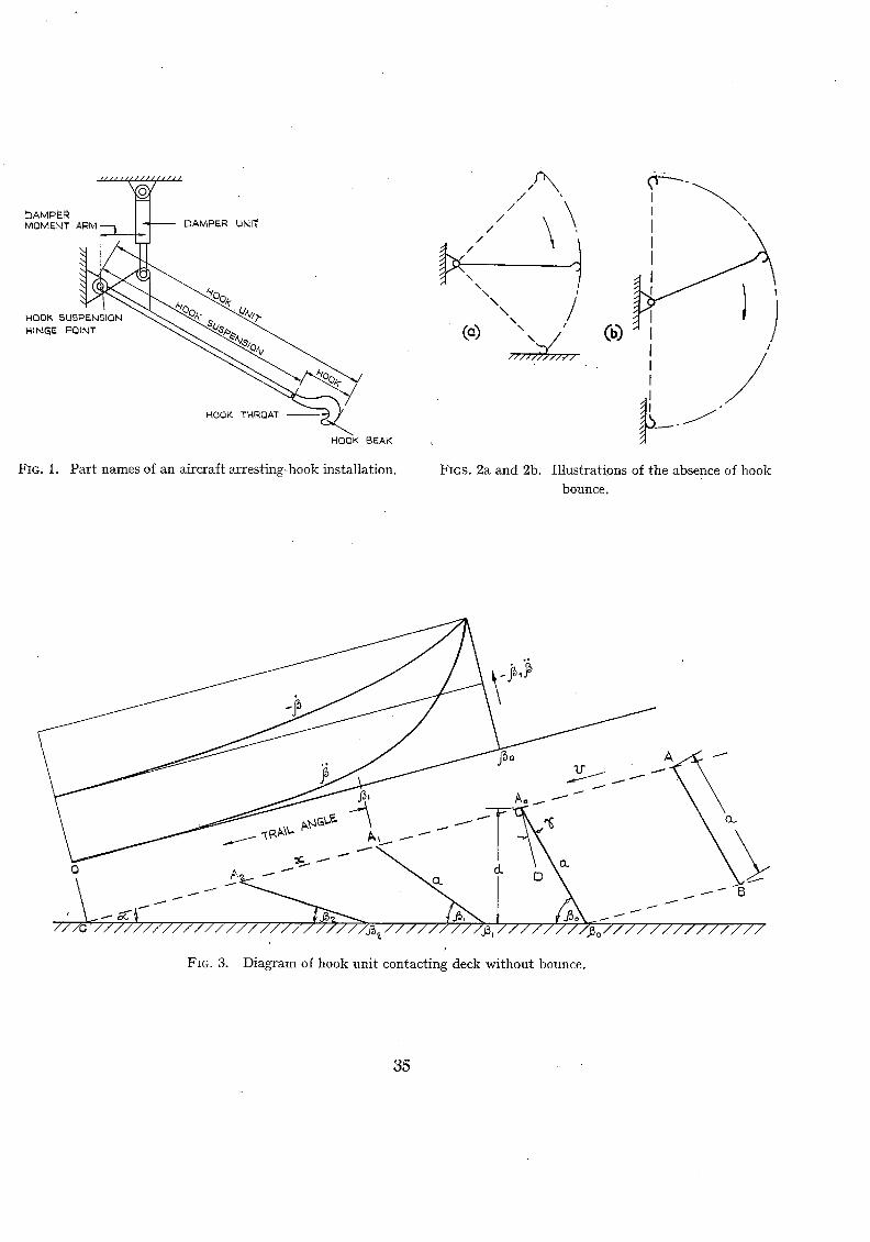
/
DAMPE..~ / / MOMENT A!~M- PER uNIT /
/
\
\ NINGIE POINT ( a ) \ z
\
/ / / l / l / l / f / -.
NOOK TNRQAT
NOOK BEAK
FIG. 1. Par t n a m e s of an aircraft arrest ing-hOok ins ta l la t ion .
I
I / I
FIGS. 2a and 2b. Il lustrations of the absence of h o o k
bounce.
t t 1 1
///G //////////////////////////~/////////~,/////~/~o//////////////
FIG. 3. Diagram of hook unit contacting deck without bounce.
35

Co
4
3
FIG. 4.
i I
IIII1"1111"/ / ~ I "tr t Q.fL
t 6 0
140
iO0
8 0
I 40
O gOo 4 0 ° 60 ° 8 0 °
INITIAL, TRAIL AI',JGi!._E J~o
Variation of initial values of angular velocity and acceleration
(-- fl0 and flo) with the initial trail angle flo
i~l il ~ l I /
A . I
, o + 7 , ] . . , . , . . . , 7 ,7 ,-.. . 77 .7 , , , , @')
Flcs. 5a and 5b. Hook striking a ramped obstruction.
FIG. 6. Trajectory of a hook bounce.
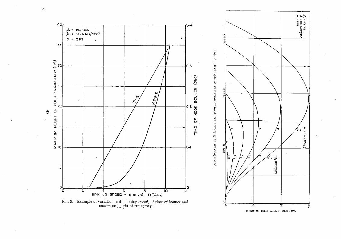
4 0
35
z~0 >-
O
(3 ILl
zs n , I---
5~ 121 o
i--
<
0 (3
FIG. 8.
i
SO D~Gi 50 RAD/SEC ~
5FT
/
Z 4 6 8 I0 IZ SINKING SPEED - Ar $1"n. ct (Fr/SE¢)
Example of variation, wi th sinking speed, of time of bounce and. maximum height of trajectory.
0.4
3 . 3
0.E
/ %-
t u
U/ O Z
O 8Q
v O O -r
O
t~
.'4
N
c9
o
o o
o
N"
5 Crq
I n i l r l (D ". O . o • ..t xl o
m
! \
; /° °
< HEt&HT OF HQQK ABOVE DECK (IN.)
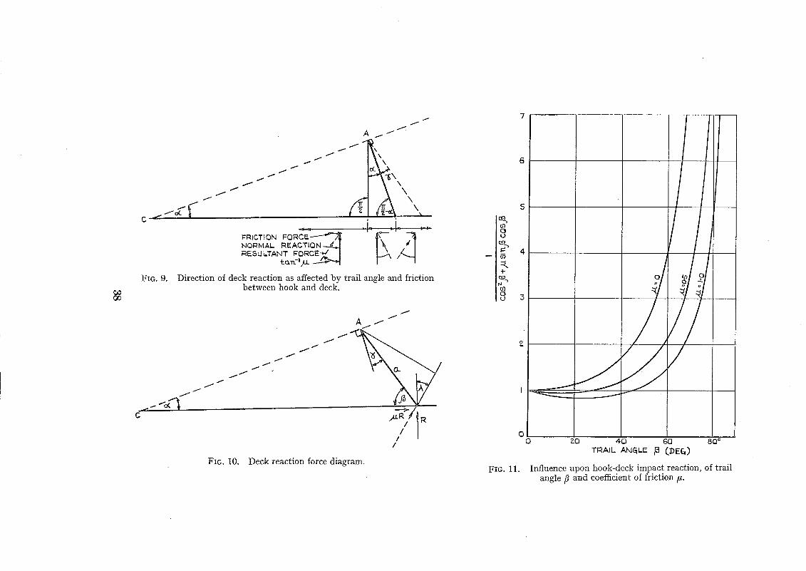
OO
/ o L C ' ""
FIG. 9.
J /
j ..-" 1o~q
C
/ /
f I
f f
f i
/ f
f
1 J
A f
\
rr~
NOrMAl- REACTION - - . ~ RESULTANT FQRGE-~/~ I
Direction of deck reaction as affected by trail angle and friction between hook and deck.
f /
j f
f f
J J
f i
/
J /
A / f
iii I I
FIG. 10. Deck reaction force diagram.
7
5
tO O t~
ID
0 0
FIG. 11.
ZO 4-0 GO 8Q ° TRAIL A,~,IGiL~ /~ (.DEG)
Influence upon hook-deck impact reaction, of trail angle/~ and coefficient of friction/~.
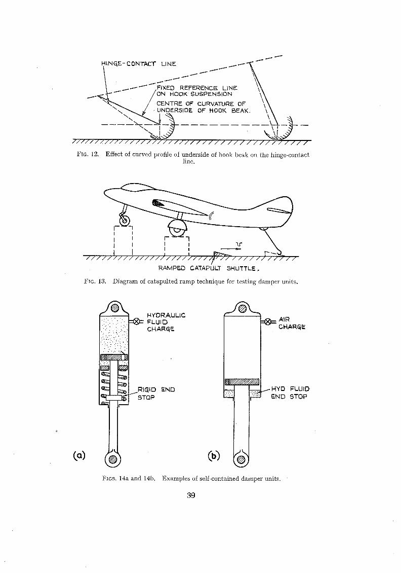
HINGE- CONTACT LINE ..~......---~'~" " " " " " ' "
\ _ ~ - 1 ~ , ~ × E o aEFERENC~ LINE \ \ l ~ . . .Y" - /ON HOOK SOSP~NS,ON '\\
" : '~""~ " / C E N T R E OF C,URVATUF~F__ OF \ \ \ < ~ Z J UNDERSIDE OF HOOK BEAK. \ \
\ \ \
. . , - . . . . . . . . - - ~ - ~ I \
I / I / / / / / / / / / / / / I / / I / / / - / / / / / / / / / / / / / / " ~ J / ~ / / /
FIG. 12. Effect of curved profile of underside of hook beak on the hinge-contact line.
I I F 1 I I I I ~ r
/ / / / / / / / / / / / / / / / / / / / / / / / ~ / / / / / / / / / / / / / / t
RAMPF..O CATAPULT SHUTTLE,.
FIG. 13. Diagram of catapulted ramp technique for testing damper units.
( - )
NYDRAULIC • .:. . . . . " : e 2 ~ F L U I D
" " : " CHAR(~E
I ' , ' , - ' - "." : ' . ' " ' . ' 1
( ®
CHARQ~
-- jHYO FLUID
END STOP
FIGS. 14a and 14b. Examples of self-contained damper units.
39
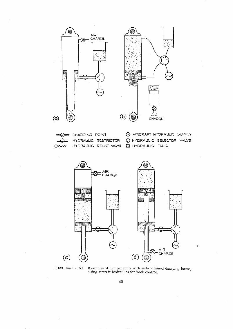
@
j ~ AIR CMARGE
~:/i!}ii iii?!Yli: : : ' , . . . . . : .~" p.::y.}..: .-
AIR CHANG5
)
O, w w v
CHARGING POINT
H'Y DRAU/IC I~.ESTRICTOR N"I'E3RAIII..,IC REIIF..,F VAL'VIg
AIRCRAFT HYDRAULIC 5!2PPL'Y
~) HYDRAULIC SELECTOR VALVE [ ] HYDRAULIC FLUID
@)
e•• I A I R CHARGE
.:,..~ o (
II
)
:.:{ :':i"
°i :'} + y
AIR
FIGS. 15a to 15d. Examples of damper units with self-contained damping forces, using aircraft hydraulics for hook control.
40
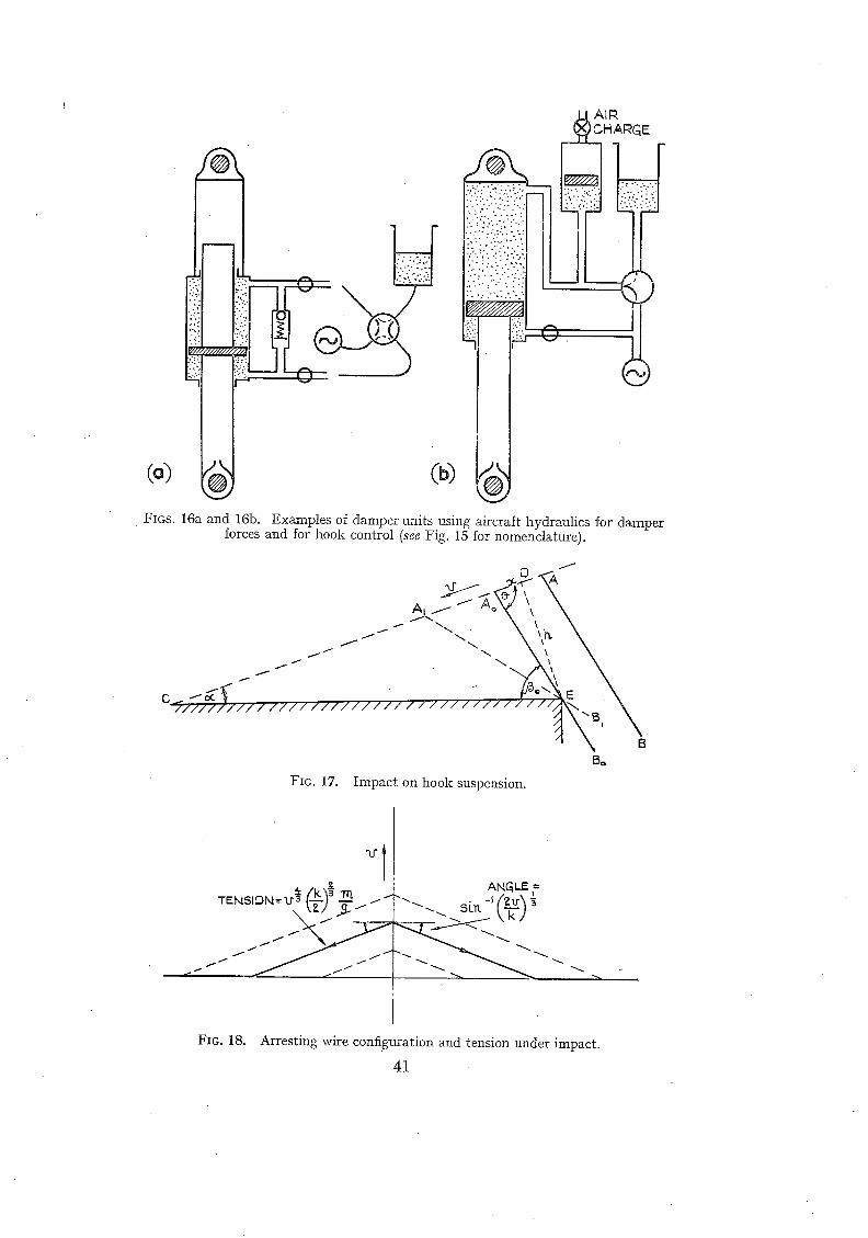
(o)
FIGS. 16a and 16b.
AIR )CHARGE
I !
I !
I
forces and for hook control (see Fig. 15 for nomenclature). Examples of damper units using aircraft hydraulics for damper
0
Ai ~" o'X"
..i I"
- ) 7 7 / 1 1 / / 1 / / / / / 1 1 / / / / / / / / / / / 1 1 / I / / /
7
fBo
FIG. 17. Impact on hook suspension.
/ I - . . . -J (zu~ --.~. S[~.
FIG. 18. Arresting wire configuration and tension under impact.
41
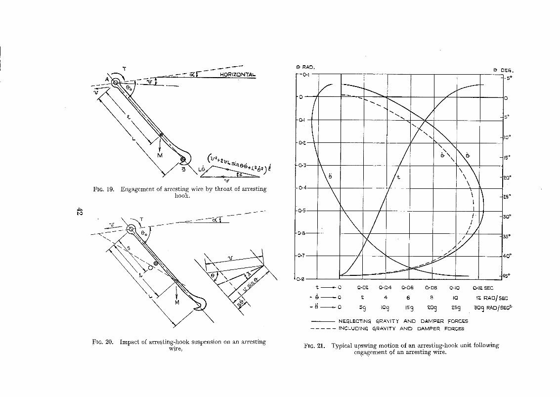
b~
A ~ . . . . . - - -7,-- ~ F ~o~zoN'rAL
Fla. 19. Engagement of arresting wire by throat of arresting hook.
8- RAD,
*|
f , /
t
/,
t
-&
\
, \ \ I
2 , / z /
/ /
,Y . 7
~" O O,O~ 0 .04 O-O6 O'O8 O-IO
L O a 4 6 8 El
o 2 9 ~ocj 5s 9 ao 9 zs 9
NEGLECTING GiRAN'ITY AND DAMDER FORCES INCLUDING Cq~AVITY A N D DAMPER FORCES
e D~G.
. 5 °
5 ~
I0 °
15 °
~0 °
~ 5 °
3 0 °
35 °
O-la SEC
I~ RAO] SEC
~o9 RAO/SEC~
FIG. 20. Impact of arresting-hook suspension on an arresting w_ire: FIG. 21. Typical upswing motion of an arresting-hook unit following
en.gagement of an arresting wire,
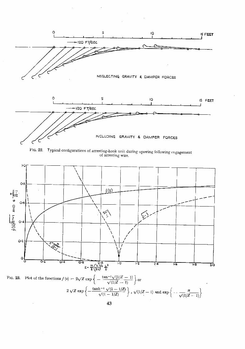
O S IO I , j I , I i , , , J , , j
---~- 120 F T/$ Er-. - - ~ - " - ~ C O O
~ ~ . NEGLECTING GRAVITY ~ DAMPEF~ FORCES
15 F E E T I
0 5 IO I i ; , , I j , , , I
120 F T/S EC " % ^ . . . . . ~ z C ' -
D A M P E R
FIG. 22.
FORCES
I I I
Typical configurations of arresting-hook unit during upswing following engagement of arresting wire.
15 FEET I
1"0
0.8
0.6 O Z <
FIG. 23.
0.4
O
I
\ \ \
\
I
I
f
/
f - -
R/
O.Z 0.4
\ \
\ \
\ / \
\ \ /
\ / \ /
\ / /
\ / \ /
~t
O;g 0.8 l .O 1.2 1"4 1.6 t . 8 ?..O
t a n - l v / ( 1 / Z -- 1) Plot of the func t i ons f (z) = 2~v/Z exp -- ~ / ( 1 / Z - - 1) or
2 ~/Z exp { t anh-1X/ (1 -- l /Z) } { - - %/(1 -- 1 / l ) , ~ v / ( 1 / Z - - 1) and exp
o} v ' ( 1 / z - ~)
4 3
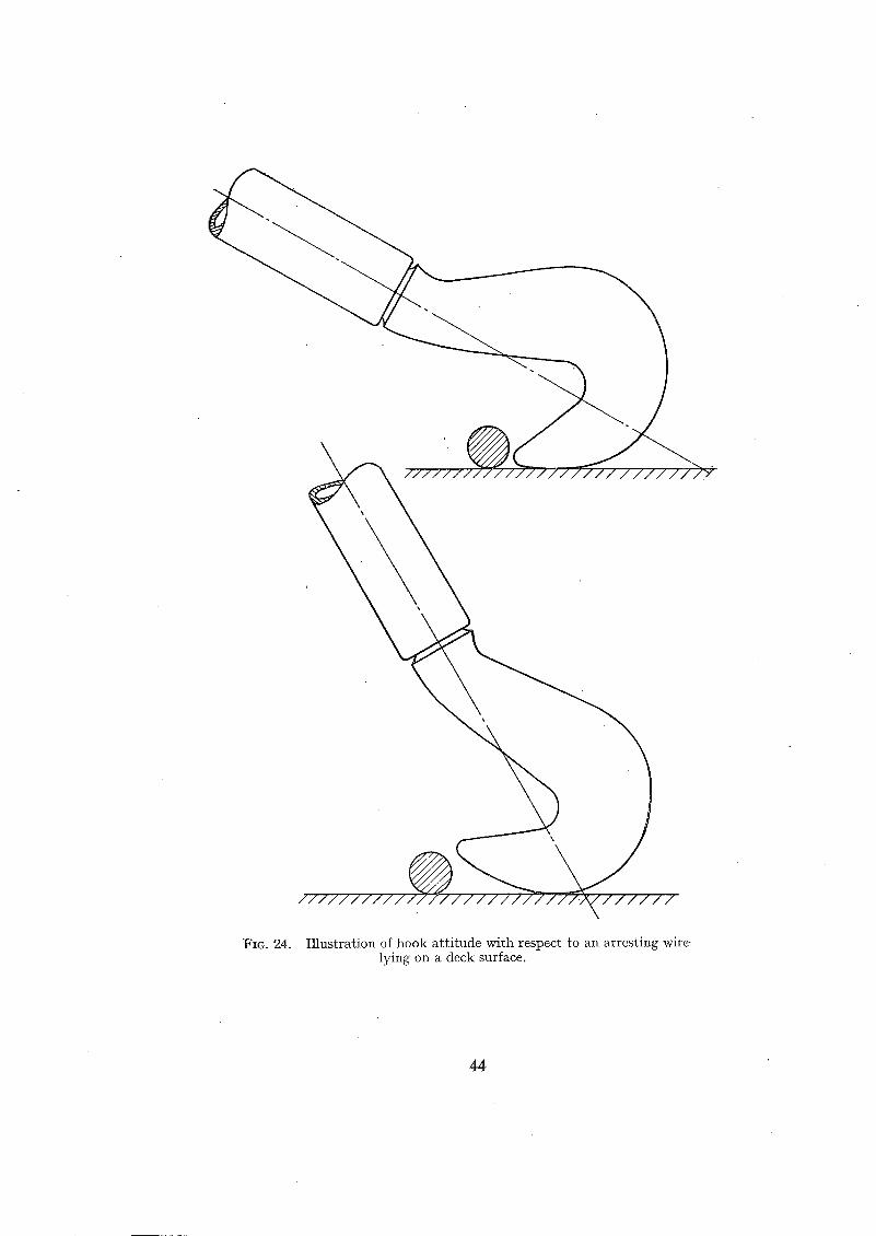
\
' \ \,
' \
. / / / / / / / / / / . //
FIG. 24. Illustration of hook attitude with respect to an arresting wire,- lying on a deck surface.
44
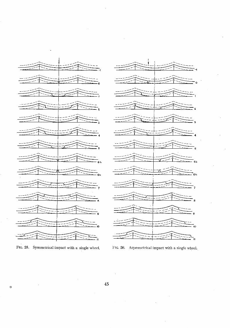
_-:
- - ~ - -
4
I 6o-
- - - ~ 6 b
7
~ ' - 8
I
FIG. 25. Symmetrical impact with a single wheel.
I
I0
£ - ~ 0 , FIG. 26. Asymmetrical impact with a single wheel.
45 D
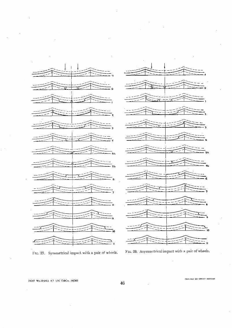
I
/
L ~
[
~ S c L
1
1
iFzG. 27. Symmetrical impact with a pair of wheels.
~ o
_ ~ s I ~ _ _ ~ ~
I
FIG. 28. Asymmetricalimpact with a pair of~wheels.
PRINTED IN GREAT BRITAIN J4367 Wt.19/8411 K7 3/56 D&Co. 34/263
46
R. & M. No. 2980
Publications of the Aeronautical Research Council
ANNUAL TECHNICAL REPORTS OF THE AERONAUTICAL RESEARCH COUNCIL (BOUND VOLUMES)
1939 Vol. I. Aerodynamics General, Performance, Airscrews, Engines. 5os. (5IS. 9d.) Vol. II. Stability and Control, Flutter and Vibration, Instruments, Structures, Seaplanes, etc.
63 s. (64 s. 9d.)
I94oAero and Hydrodynamics, Aerofoils, rAirscrews, Engines, Flutter, Icing, Stability and Control, Structures, and a miscellaneous section. 5os. (5IS. 9d.)
1941 Aero and Hydrodynamics, Aerofoils, Airscrews, Engines, Fiutter, Stability and Control, Structures. 63 s. (64s. 9d.)
1942 Vol. I. Aero and Hydrodynamics, Aerofoils, Airscrews, Engines. 75s. (76s. 9d.) Vol. II. Noise, Parachutes, Stability and Control, Structures, Vibration, Wind Tulmels. 47s. 6d.
(49 s. 3d.) 1943 Vol. I. Aerodynamics, Aerofoiis, Airserews. 8os. (Sis. 9d.)
Vol. II. Engines, Flutter, Materials, parachutes, Performance, Stability and Control, Structures. 9os. (92s. 6d.)
1944 VoL I. Aero and Hydrodynamics, Aerofoils, Aircraft, Airscrews, Controls. 84 s. (86s. 3d.) Vol. II. Flutter and Vibration, Materials, Miscellaneous, Navigation, Parachutes, Performance,
Plates and Panels, Stability, Structures, Test Equipment, Wind Tunnels. 84 s. (86s. 3d.) 1945 Vol. I. Aero and Hydrodynamics, Aerofoils. I3OS. (I32S. 6d.)
Vol. II. Aircraft, Airscrews, Controls. I3OS. (I32S. 6d.) Vol. III . Flutter and Vibration, Instruments, Miscellaneous, Parachutes, Plates a n d Panels,
Propulsion. I3OS (I32S. 3d.) . Vol. IV. Stability, Structures, Wind tunnels , Wind Tunnel Technique. I3OS. (132s. 3d.)
ANNUAL REPORTS OF THE AERONAUTICAL RESEARCH COUNCIL--
1937 2s. (2s. 2d.) 1938 is. 6d. (IS. 8d.) 1939-48 3 s. (3s. 3d.) INDEX TO ALL REPORTS AND MEMORANDA PUBLISItED 1N THE ANNUAL TECHNICAL
REPORTS, AND SEPARATELY--
April, 195o . . . . . R. & M. No. 26oo. 2S. 6d. (2s. 8d.)
AUTHOR INDEX TO ALL REPORTS AND MEMORANDA OF THE AERONAUTICAL RESEARCH COUNCIL--
I9O9-January, 1954 - - - R. & M. No. 2570. I5S. (I5 s. 6d.)
INDEXES TO THE TECHNICAL REPORTS OF THE AERONAUTICAL RESEARCH COUNCIL--
December 1, 1936- -June 3o, I939. July I, 1939 - - June 3o, 1945. - , i
J u l y I, 1945 - - June 3o, 1946. - July I , 1946 - - December 31, 1946. January 1, 1 9 4 7 - June 30, 1947. -
R. & M. No. 185o. IS. 3 d. (IS. 5d.) R. • M. No. r 195o. IS. (IS. 2d.) R" &F M" NO" 2050" ~ S" (IS" 2d') R. & M. No. 215o. IS. 3 d. (IS. 5d.) R . & M. No. 2250. IS. 3d. (IS. 5d.)
PUBLISHEDREPORTS AND MEMORANDA OF THE AERONAUTICAL RESEARCH COUNCIL---
Between Nos. 2251-2349. - - R. & M, No. 235o. Between Nos. 2351-2449. - - R. & M. No. 245o. Between Nos. 2451-2549. - - R. & M. No. 255o. Between Nos. 2551-2649. - - R. & M. No. 2650.
Prices in brackas include postage
H E R MAJESTY'S S T A T I O N E R Y OFFICE York House, KJngsway, Lonclon W.C.2; 423 Oxford Street, London W.I ;
13a Castle Street, Edinburgh 2; 39 King Street, Manehe.~ter 2; 2 Edmund Street, Birmingham 3; 109 SL Mary S t ru t , Cardiff; Tower Lane, Bristol 1 ; 80 Chlehe~ter Street, Belfast, or through any bookseller ,
lS. 9 d. (IS. IId.) 2s. (as. 2a.) 2s. 6d. (2s. 8d.) 2s. 6d. (2s. 8d.)
S.O. Code No. 23-2980
R . & M. No. 2980