Embed Size (px)
Citation preview

Purdue UniversityPurdue e-Pubs
International Compressor Engineering Conference School of Mechanical Engineering
2010
A Study of Flapper Valve Motion in a VariableSpeed CompressorDouglas Andrew CollingsTecumseh Products Company
James R. LenzTecumseh Products Company
Follow this and additional works at: https://docs.lib.purdue.edu/icec
This document has been made available through Purdue e-Pubs, a service of the Purdue University Libraries. Please contact [email protected] foradditional information.Complete proceedings may be acquired in print and on CD-ROM directly from the Ray W. Herrick Laboratories at https://engineering.purdue.edu/Herrick/Events/orderlit.html
Collings, Douglas Andrew and Lenz, James R., "A Study of Flapper Valve Motion in a Variable Speed Compressor" (2010).International Compressor Engineering Conference. Paper 2001.https://docs.lib.purdue.edu/icec/2001

1343, Page 1
International Compressor Engineering Conference at Purdue, July 12-15, 2010
A Study of Flapper Valve Motion in a Variable Speed Compressor James R. Lenz*, Douglas Collings P.E.
Tecumseh Products Company,
1136 Oak Valley Drive Ann Arbor, MI, 48108
USA
Contact Information ([email protected])
* Corresponding Author
ABSTRACT
This study is an attempt to determine if there is any speed sensitive phenomenon in flapper valve operation. Valve motion is measured at various speeds in a reciprocating residential refrigerator/freezer compressor. Laser Doppler Velocimetry is used to measure the velocity of a point on the flapper at the center of the port for the suction valve. This velocity data is numerically integrated to produce displacement as a function of crank angle for each speed. An attempt is made to correlate compressor speed with any behavior that might either improve compressor performance or, conversely, decrease valve life.
1. INTRODUCTION 1.1 Objective The design of the flapper valves has a significant effect on the reliability and performance of compressors. Although a significant effort has been made to estimate valve motion through the use of computer simulation (see for example Figure 1), confirmation of these results have typically been inferred from either endurance or rating test results. The objective of this experiment is to directly measure the motion of a suction valve during normal compressor operation at various speeds and determine if there is any speed sensitive phenomenon.
Figure 1. An example of simulated suction valve motion
1343, Page 2
International Compressor Engineering Conference at Purdue, July 12-15, 2010
1.2 Experimental Concerns There were three primary experimental concerns;
• Test Housing capability • Laser measurement capability. • Data acquisition
Unresolved issues in any of these areas would mean that the project would not be successful.
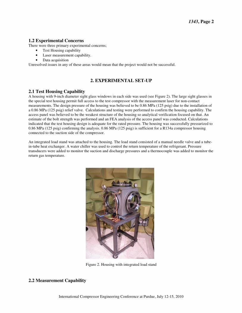
2. EXPERIMENTAL SET-UP 2.1 Test Housing Capability A housing with 9-inch diameter sight glass windows in each side was used (see Figure 2). The large sight glasses in the special test housing permit full access to the test compressor with the measurement laser for non-contact measurements. The design pressure of the housing was believed to be 0.86 MPa (125 psig) due to the installation of a 0.86 MPa (125 psig) relief valve. Calculations and testing were performed to confirm the housing capability. The access panel was believed to be the weakest structure of the housing so analytical verification focused on that. An estimate of the bolt strength was performed and an FEA analysis of the access panel was conducted. Calculations indicated that the test housing design is adequate for the rated pressure. The housing was successfully pressurized to 0.86 MPa (125 psig) confirming the analysis. 0.86 MPa (125 psig) is sufficient for a R134a compressor housing connected to the suction side of the compressor. An integrated load stand was attached to the housing. The load stand consisted of a manual needle valve and a tube-in-tube heat exchanger. A water chiller was used to control the return temperature of the refrigerant. Pressure transducers were added to monitor the suction and discharge pressures and a thermocouple was added to monitor the return gas temperature.
Figure 2. Housing with integrated load stand
2.2 Measurement Capability

1343, Page 3
International Compressor Engineering Conference at Purdue, July 12-15, 2010
The measurement capability of the laser was also unknown. The initial concern was the ability of the laser vibrometer to accurately measure motion thru the windows of the housing. An initial test was run using a shaker with both a wired accelerometer and a piece of reflective tape attached to the armature. When overlaid, the two waveforms appeared identical. Next a compressor was prepared including a hole in the cylinder head for access to the suction valve and modifications to facilitate solid mounting in the housing (see Figure 3). The mounting of the housing on the cart and the cart itself were modified to improve measurement accuracy by increasing the rigidity of the entire system. After the laser was focused properly on the valve, the laser was able to accurately measure the movement of the suction valve.
Figure 3. Compressor with encoder mounted in housing
One significant challenge has been assuring that an adequate response signal is returned to the laser. The power of the laser is fairly limited. The surface must be reflective enough to return an adequate amount of light for the laser to recognize. The surface must also be diffuse enough to return an adequate amount of light to the laser across the full range of valve motion. The surface of a production suction valve is too smooth and the reflection is not diffuse enough, resulting in unstable response. The laser manufacturer suggested using glass beads attached to the valve by either hairspray or superglue. Hairspray did not have a strong enough bond and all the beads fell off after a short period of running. Superglue worked better but the response was unreliable. In the end, retro- reflective tape was found to have the most consistent response. The adhesive held the tape in place during operation with open air. The adhesive appears to be capable of short exposure to refrigerant and oil. However, after longer exposure to refrigerant and oil of a week or more the tape did not remain on the valve satisfactorily. There is also a significant amount of random noise due to oil droplets passing through the laser beam. A number of solutions were proposed including adding a sight tube between the cylinder head and the observation window, in the end however the oil was simply drained from the housing. Draining the oil combined with averaging a large number of samples substantially reduced the amount of random errors. The refraction angle of the laser with the observation window is also important. If the laser is normal to the window, the reflection from the window interferes with reflection from the valve. It is necessary to have the laser at a slight angle to the window, to separate the window reflection from the valve reflection.
1343, Page 4
International Compressor Engineering Conference at Purdue, July 12-15, 2010
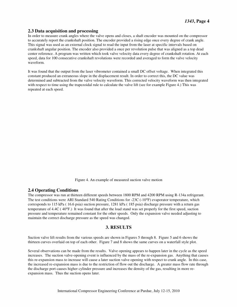
2.3 Data acquisition and processing In order to measure crank angles where the valve opens and closes, a shaft encoder was mounted on the compressor to accurately report the crankshaft position. The encoder provided a rising edge once every degree of crank angle. This signal was used as an external clock signal to read the input from the laser at specific intervals based on crankshaft angular position. The encoder also provided a once per revolution pulse that was aligned as a top dead center reference. A program was written which took valve velocity data every degree of crankshaft rotation. At each speed, data for 100 consecutive crankshaft revolutions were recorded and averaged to form the valve velocity waveform. It was found that the output from the laser vibrometer contained a small DC offset voltage. When integrated this constant produced an extraneous slope in the displacement result. In order to correct this, the DC value was determined and subtracted from the valve velocity waveform. This corrected velocity waveform was then integrated with respect to time using the trapezoidal rule to calculate the valve lift (see for example Figure 4.) This was repeated at each speed.
Figure 4. An example of measured suction valve motion 2.4 Operating Conditions The compressor was run at thirteen different speeds between 1800 RPM and 4200 RPM using R-134a refrigerant. The test conditions were ARI Standard 540 Rating Conditions for -23C (-10°F) evaporator temperature, which corresponds to 115 kPa ( 16.6 psia) suction pressure, 1281 kPa ( 185 psia) discharge pressure with a return gas temperature of 4.4C ( 40°F.) It was found that after the load stand was set properly for the first speed, suction pressure and temperature remained constant for the other speeds. Only the expansion valve needed adjusting to maintain the correct discharge pressure as the speed was changed.
3. RESULTS
Suction valve lift results from the various speeds are shown in Figures 5 through 8. Figure 5 and 6 shows the thirteen curves overlaid on top of each other. Figure 7 and 8 shows the same curves on a waterfall style plot. Several observations can be made from the results. Valve opening appears to happen later in the cycle as the speed increases. The suction valve-opening event is influenced by the mass of the re-expansion gas. Anything that causes this re-expansion mass to increase will cause a later suction valve opening with respect to crank angle. In this case, the increased re-expansion mass is due to the restriction of flow out the discharge. A greater mass flow rate through the discharge port causes higher cylinder pressure and increases the density of the gas, resulting in more re-expansion mass. Thus the suction opens later.

1343, Page 5
International Compressor Engineering Conference at Purdue, July 12-15, 2010
Observations about the dynamic motion of the valve can be made as well. The number of humps in the suction valve motion decreases as the speed increases. This is an indication that the dynamic motion of the valve, while it is open, is governed by its first natural vibration mode. The time between humps is fixed by the first natural mode of the valve, while the time the valve is open gets smaller as the compressor speed is increased. Therefore fewer humps can occur at higher compressor speeds. Although the humps get farther apart when measured in crankshaft degrees (as shown in Figures 5 and 6), the actual time between humps is fixed. Finally, it can be seen that the opens farther initially, as the speed increases. This is due to the higher mass flow rate which causes more pressure drop across the valve, especially at the beginning of the suction process when the inertia of the valve “resists” its opening. The result of the valve opening farther is higher bending stresses. These higher bending stresses should be taken into account when designing compressor valves for variable speed operation.
-0.50
0.00
0.50
1.00
1.50
2.00
2.50
3.00
3.50
0 60 120 180 240 300 360
Crank Angle (deg)
Val
ve L
ift
(mm
)
1800rpm 2000rpm 2200rpm 2400rpm 2600rpm 2800rpm 3000rpm
3200rpm 3400rpm 3600rpm 3800rpm 4000rpm 4200rpm
Figure 5: Suction Valve Motion at Various Speeds vs. Crank Angle – overlay
-0.50
0.00
0.50
1.00
1.50
2.00
2.50
3.00
3.50
0 0.005 0.01 0.015 0.02 0.025 0.03 0.035
Time (sec)
Val
ve L
ift
(mm
)
1800 rpm 2000rpm 2200rpm 2400rpm 2600rpm 2800rpm 3000rpm
3200rpm 3400rpm 3600rpm 3800rpm 4000rpm 4200rpm
Figure 6: Suction Valve Motion at Various Speeds vs. Time - overlay

1343, Page 6
International Compressor Engineering Conference at Purdue, July 12-15, 2010
Figure 7: Suction Valve Motion at Various Speeds vs. Crank Angle - waterfall
Figure 8: Suction Valve Motion at Various Speeds vs. Time – waterfall
4. CONCLUSIONS
The goal of this project was to measure the suction valve motion at various speeds. This goal was accomplished. Laser Doppler Velocimetry is a viable way to measure valve motion. Some limitations of the laser were uncovered including oil mist and droplets, reflections and surface treatment. These may be overcome to some degree by the use of a more powerful laser.

1343, Page 7
International Compressor Engineering Conference at Purdue, July 12-15, 2010
REFERENCES
Buligan, G., Paone, N., Revel, G., Tomasini, E., 2002, Valve lift measurement by optical techniques in compressors, Proceedings of the Sixteenth International Compressor Engineering Conference at Purdue, paper C13-5
Conte, S, de Boor, C, 1972, Elementary Numerical Analysis, McGraw-Hill, Inc., p. 287 Lenz, J, 2000, Finite Element Analysis of Dynamic Flapper Valve Stresses, Proceedings of the 2000 International
Compressor Engineering Conference at Purdue, p. 369-373� Nagy, D., Almbauer, R.,Lang, W., Burgstaller, A., 2008, Valve Lift Measurement for the Validation of a
Compressor Simulation Model, Proceedings of the Nineteenth International Compressor Engineering Conference at Purdue, paper 1274
Prasad, B., Woollatt, D., 2000, Valve Dynamic measurements in an VIP compressor, Proceedings of the 2000
International Compressor Engineering Conference at Purdue, p. 361-368 Real, M., Pereira, E., 2009, Measuring Hermetic compressor Valve Lift using Fiberoptic Sensors, Proceedings of the
7th IIR International Conference on Compressors and Coolants
ACKNOWLEDGEMENT The authors would like to acknowledge Jeremy Mommerency of Tecumseh Products Company for his assistance with programming and data acquisition.