Embed Size (px)
Citation preview

I
i
6 5c . /
Station Paper No. 55 December I960
A STUDY OF
EARLY GULLY-CONTROL STRUCTURESin the Colorado Front Range
... ^—»V-
by
Burchard H. HeedeResearch Forester
Forest Service U.S. Department of AgricultureRocky Mountain Forest and Range Experiment StationFort Collins, Colorado Raymond Price, Director

Denver
MANITOUEXR FOREST
ROUT GRK,
W A T E R S H E DColorodo
S p r i n g s
L O C A T I O N O F S T U D Y A R E A S

rA S T U D Y O F E A R L Y G U L L Y - C O N T R O L S T R U C T U R E S
IN THE C O L O R A D O F R O N T R A N G E
by
Burchard H. Heede, Research Forester1
C O N T E N T SPage
Introduction 1
Purpose 1
Method 1
The study 2
Nursery gully system 2Upper Trout Creek gully 13Small Tributary gully 13Reuter gully 13
Principles of gully control 22
Classification of gullies 22Mechanics of gullying 22Critical locations in gully systems 24Design of check dams 25Protection of gully banks 31Plantings 34Treatment of gully systems 34
Recommendations 35
Bibliography 37
Appendix 39
Examples of gully control 39Sample of field data form 41Expected peak flows and maximum discharge
capacities of check dams 42
Rocky Mountain Forest and Range Experiment Station, with central head-quarters maintained in cooperation with Colorado State University at Fort Collins.
A S T U D Y O F E A R L Y G U L L Y - C O N T R O L S T R U C T U R E S
IN THE C O L O R A D O FRONT RANGE
by
Burchard H. Heede, Research Forester
^ I N T R O D U C T I O N
The control of gullies is an important step in watershed rehabilitation.Gully control designed to fix valley bottoms at a certain base level stabilizesthe valley floor through sediment accumulation in the gully channel. Thisreduces sediment deposition in river streambeds and enhances the quality ofwater supplies. Benefits of a gully-control program accrue to both on-siteand downstream users alike.
The purposes of the present study were:
1. To evaluate gully-control structures installed 20 to 25 yearsago on the Pike and San Isabel National Forests.
2. To show the role of check dams in gully control.
JME_T_HO_D_
As a basis for estimating stormflow at a particular structural site, adesign storm with a total of 2 inches of precipitation was used. Such a de-sign storm was computed from the records at the Manitou ExperimentalForest.
Average infiltration curves were established for the different vegetation-soil complexes (i.e., open timber-granitic, grass -granitic alluvium, etc.).Application of these curves to the rainfall pattern of the design storm yieldedthe rainfall excess (runoff) for each of the vegetation-soil complexes.
-The peak flow from the storm was obtained by plotting the flow distri-
bution of 10 -minute periods in relation to their time difference on one chart..
To facilitate the survey of the watersheds and their drainage basins, aradial-line plotter was used on aerial photographs to determine:
1. Total acres of each drainage basin;
2. Acres in drainage segments;
3. -Acres of vegetation-soil types within each drainage segment.
Peak flows at a given structure were determined by multiplying theacres in a segment above the structure by the peak flows per acre for thedifferent vegetation-soil complexes within the segment.
- 1 -

TDischarge rating curves were constructed for 1 -foot-long broadcrested
weirs of different heights and different breadths.
Photographs are the only record of the rehabilitation work in the 19SO's.Therefore, the intended purpose of the structures was interpreted from thephotographs taken at the time of construction. Early reports state that theoverall purpose of the check dams was "to establish new base levels in re-juvenated channels" (Bailey and Croft, 1937).
Within limits the deposition of sediment behind a dam indicated a suc-cess and the lack of deposits a failure. Sometimes, it was found that a damaccomplished its objective but failed at a later date. In the case of deteriora-tion of the construction, material, the structure was considered a success ifit apparently accomplished its purpose during the life of the constructionmaterial.
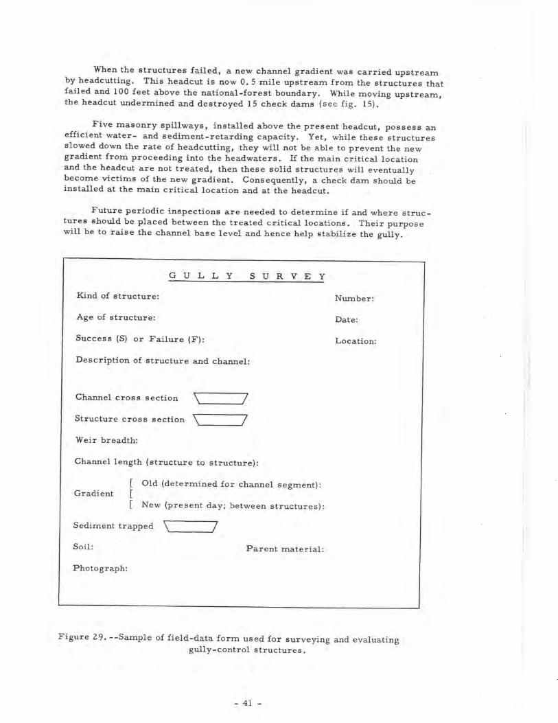
Tape, survey rod, and Abney hand level were used to determine originalvalley bottom slope, channel gradient before and after treatment, and channeland structural cross sections. The structures were numbered and the obser-vations are summarized in table 1, page 42. A special field-data form forsurveying and evaluating gully control structures was designed (see fig. 29,page 41.
TjiE S T U D Y
NURSERY GULLY SYSTEM, MANITOU EXPERIMENTAL FOREST
The Manitou Experimental Forest is situated in the Colorado FrontRange 28 miles northwest of Colorado Springs in the upper headwaters of theSouth Platte drainage. The average annual precipitation is 1 5 inches. Thecritical factor for erosion is the cloudbursts of high intensity and shortduration during the summer months.
The watershed of the Nursery gully system is within the ponderosapine-bunchgrass zone and covers 360 acres. It is rather long and narrow,with the main axis running from east to west. The main stream course is1. 5 miles long. It starts in the forested headwaters at an elevation of about8,000 feet; follows the main valley floor, covered by open timber stands andgrasslands; and then discharges into the flood plain of Trout Creek at approxi-mately 7, 500 feet. The forest occupies 80 percent of the total drainage area.The soils are derived mainly from Pikes Peak granite. Slopes at the head-water area range between 20 and 30 percent, but the maximum slope of thevalley floor is 10 percent. The ephemeral flow has cut gullies of varyingwidth and depth in the drainageways. Measured maximum gully width was46 feet and maximum depth was 6 feet.
Channel characteristics, treatment, and present-day conditions areshown in figures 1-10.
_ 2 -

%v^rt^«;.4%f"f;|
' ' " "
"'":"'*' 't». i '.--- ;.> ' - : "5K.;>'^; " •:rfM^P c\2 '-'r^V^"^^" • '\ '% % '^'-'^V^^jiftsiE"
Figure l.-'The upper drainage of the Nursery gully follows an abandoned
wagon road that is still visible where gullying has not taken place. Gully
erosion is very active; headcuts mark the beginning of individual gullies.
(Height of rod = 5. 5 feet.)
- 3 -
'; <S5aP
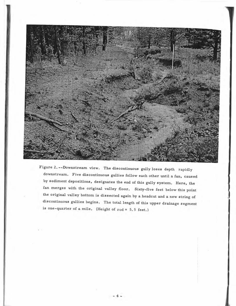
Figure 2.—Downstream view. The discontinuous gully loses depth rapidly
downstream. Five discontinuous gullies follow each other until a fan, caused
by sediment depositions, designates the end of this gully system. Here, the
fan merges with the original valley floor. Sixty-five feet below this point
the original valley bottom is dissected again by a headcut and a new string of
discontinuous gullies begins. The total length of this upper drainage segment
is one-quarter of a mile. (Height of rod = 5. 5 feet.)
- 4 -
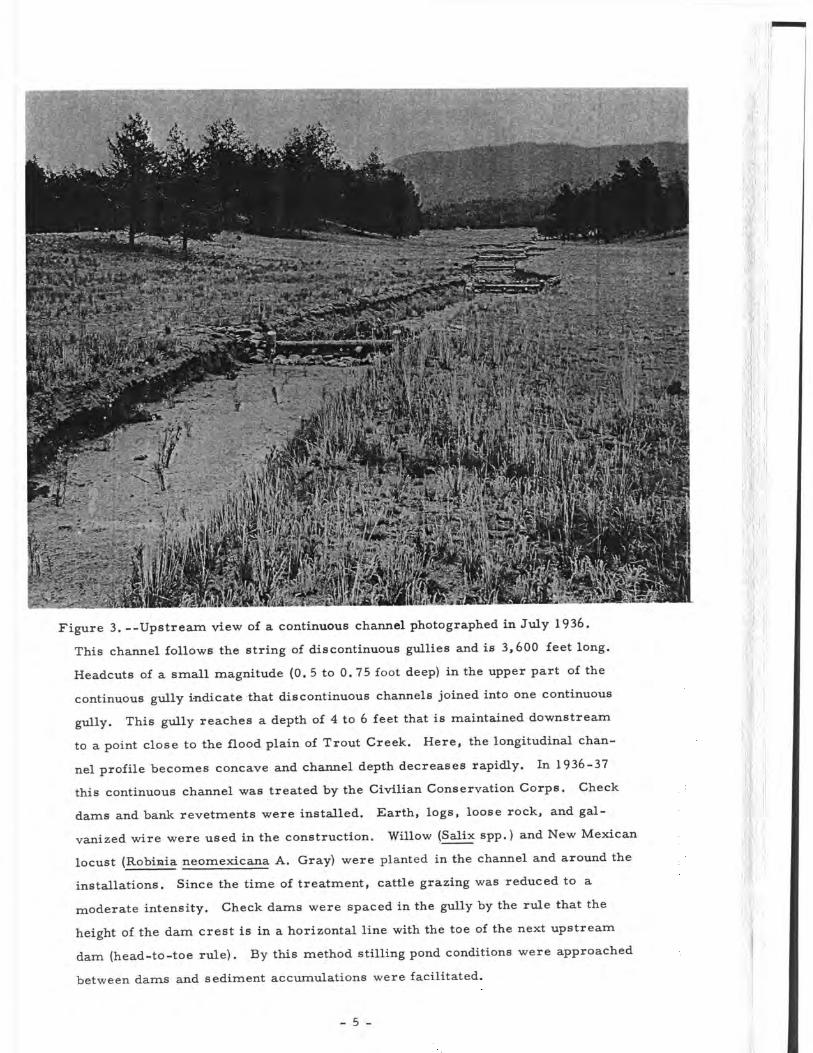
Figure 3. --Upstream view of a continuous channel photographed in July 1936.
This channel follows the string of discontinuous gullies and is 3,600 feet long.
Headcuts of a small magnitude (0.5 to 0. 75 foot deep) in the upper part of the
continuous gully indicate that discontinuous channels joined into one continuous
gully. This gully reaches a depth of 4 to 6 feet that is maintained downstream
to a point close to the flood plain of Trout Creek. Here, the longitudinal chan-
nel profile becomes concave and channel depth decreases rapidly. In 1936-37
this continuous channel was treated by the Civilian Conservation Corps. Check
dams and bank revetments were installed. Earth, logs, loose rock, and gal-
vanized wire were used in the construction. Willow (Salix spp.) and New Mexican
locust (Robinia neomexicana A. Gray) were planted in the channel and around the
installations. Since the time of treatment, cattle grazing was reduced to a
moderate intensity. Check dams were spaced in the gully by the rule that the
height of the dam crest is in a horizontal line with the toe of the next upstream
dam (head-to-toe rule). By this method stilling pond conditions were approached
between dams and sediment accumulations were facilitated.
- 5 -
/*? ; -N^r^-a«•*... '. ?.„ . l^fex .*•«-.
-S^ £r£rij
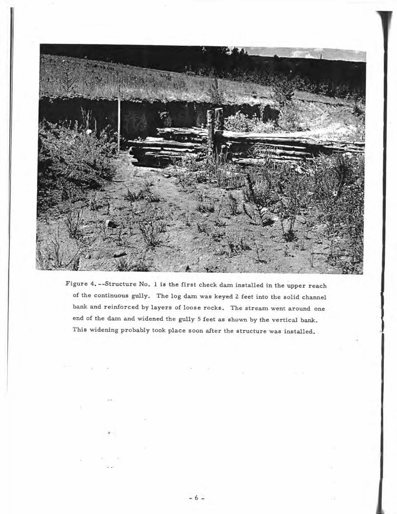
Figure 4. --Structure No. 1 is the first check dam installed in the upper reach
of the continuous gully. The log dam was keyed 2 feet into the solid channel
bank and reinforced by layers of loose rocks. The stream went around one
end of the dam and widened the gully 5 feet as shown by the vertical bank.
This widening probably took place soon after the structure ^vas installed.
- 6 -
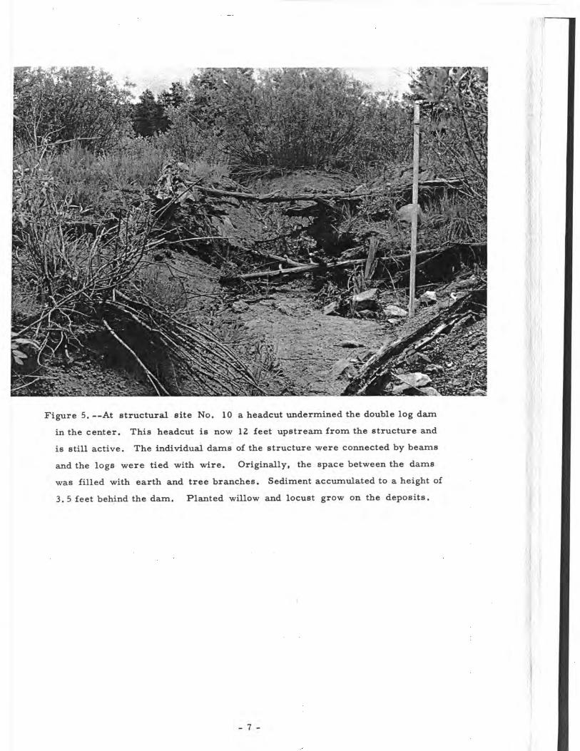
Figure 5.—At structural site No. 10 a headcut undermined the double log dam
in the center. This headcut is now 12 feet upstream from the structure and
is still active. The individual dams of the structure were connected by beams
and the logs were tied with wire. Originally, the space between the dams
was filled with earth and tree branches. Sediment accumulated to a height of
3.5 feet behind the dam. Planted willow and locust grow on the deposits.
- 7 -

Figure 6. —In the channel reach below structure No. 10 a new gully, caused by
the headcut shown in figure 5, dissects the sediment deposits that were accumu-
lated by a lower structure. The new gully meanders around the willow stands.
With increasing channel depth the flow undercut the willows, tumbling them into
the new gully. Erosion was accelerated by the soil loosened by the falling
willows. (Height of rod = 5 . 5 feet .)
- 8 -
:vfe;la*ii
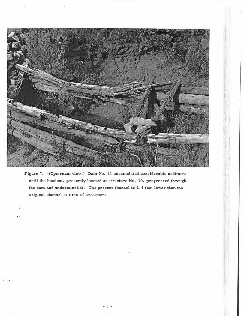
Figure 7. —(Upstream view.) Dam No. 11 accumulated considerable sediment
until the headcut, presently located at structure No. 10, progressed through
the dam and undermined it. The present channel is 2. 5 feet lower than the
original channel at time of treatment.
- 9 ~
'
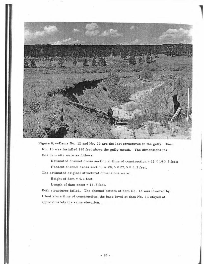
fcFigure 8. —Dams No. 12 and No. 13 are the last structures in the gully. Dam
No. 13 was installed 180 feet above the gully mouth. The dimensions for
this dam site were as follows:
Estimated channel cross section at time of construction = 1 1 X 1 9 X 5 feet;
Present channel cross section = 20. 5 X 27. 5 X 5 . 3 feet.
The estimated original structural dimensions were:
Height of dam = 4. 2 feet;
Length of dam crest = 1 2 . 5 feet.
Both structures failed. The channel bottom at dam No. 12 was lowered by
1 foot since time of construction; the base level at dam No. 13 stayed at
approximately the same elevation.
- 10 -

Figure 9. --Where the main gully and a tributary join, crib jetties were
installed at a 45° angle to the direction of the main stream. The flow
from the tributary forces the main stream against the bank opposite to the
point of inflow. Here, the gully had widened before the jetties were built.
No bank erosion occurred after treatment. The opposite bank shows signs
of cutting that took place during the early years of treatment. :: •.
- 11 -
M:iM%
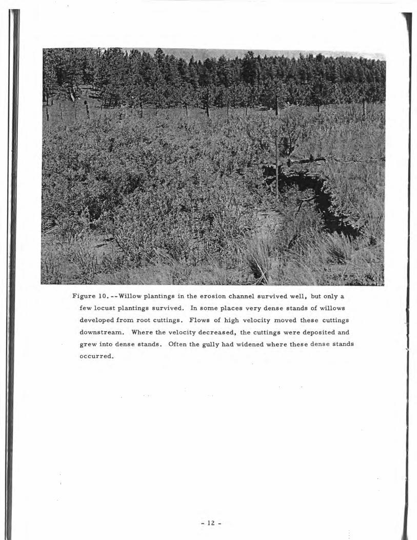
Figure 10. --Willow plantings in the erosion channel survived well, but only a
few locust plantings survived. In some places very dense stands of willows
developed from root cuttings. Flows of high velocity moved these cuttings
downstream. Where the velocity decreased, the cuttings were deposited and
grew into dense stands. Often the gully had widened where these dense stands
occurred.
1
- 12 -
UPPER TROUT CREEK GULLY, SAN ISABEL NATIONAL FOREST
The Trout Creek watershed, a part of the Upper Arkansas Valley, is5 miles east of the city of Buena Vista. U. S. Highway 24 traverses thedrainage basin.
In 1957 rain gages were installed in the lower end of the watershed.Total precipitation for 1958 amounted to 7. 31 inches and for 1959, 15.00 inches.Storms of high intensity -and short duration are common. Long-term weatherrecords are not available.
The upper Trout Creek gully starts as a series of shoestring gullies belowTrout Creek Pass at an elevation of approximately 9,400 feet. In the mainvalley floor, the ephemeral stream runs in a continuous channel that entersthe wide valley of Chubbs Park at about 8, 900 feet. This drainage is about1. 5 miles long and covers 800 acres. Maximum gully width is 64 feet andmaximum depth is 12 feet. Average channel depth ranges between 4 and6 feet. At the lower end of the watershed, the longitudinal gully profile be-comes concave and channel depth decreases.
.Soils are derived from sedimentary material, mainly shale, siltstone,
and sandstone. The vegetation type is ponderosa pine-bunchgrass. Forestsoccur on the headwater area and on the ridges surrounding the drainage basin.They occupy 70 percent of the area; the remaining portion is grassland.
Gully characteristics, gully-control measures, and the present-day con-ditions of channel and structures are described by figures 11-16.
SMALL TRIBUTARY GULLY, TROUT CREEK WATERSHED,
SAN ISABEL NATIONAL FOREST
The Small Tributary gully is a side branch of a larger erosion channelthat feeds its ephemeral flow into Trout Creek. The drainage area of SmallTributary covers 2 acres. The shallow residual soils are derived from de-composed granite rocks and are of low fertility. Vegetation is mostly bunch-grasses, with a few pinyon (Pinus edulis Engelm.). Gully characteristics andmechanical treatment are illustrated in figure 17.
.
.REUTER GULLY, TROUT CREEK WATERSHED,
SAN ISABEL NATIONAL FOREST
Reuter gully, a tributary to Mushroom Gulch that discharges its ephemeralflow into Trout Creek, has a length of 0. 5 mile and a drainage area of 75 acres.The soils are developed from granite. In the lower end of the basin the soils aremore severely eroded, and nearly all of the original surface layer is lost. Theridges surrounding the drainage are covered by open stands of ponderosa pine(Pinus ponderosa Laws.). Bunchgrasses occupy most of the grassland on thevalley floor.
The gully starts in the headwaters as shoestring gullies that join into acontinuous channel on the main valley floor. Approximately one-third (745 feet)of the total gully length was surveyed. Maximum gully depth was 5. 5 feet andmaximum width was 25. 5 feet. The treatment of the gully and its present con-dition are illustrated and described by figures 18 and 19.
- 1 3 -

Figure 11.--In 1933-34, the U. S. Civilian Conservation Corps treated the
gully by check dams and willow plantings. In the upper part of the
watershed shown here the channel banks were graded to an angle of rest.
Since 1937 no livestock have grazed the national-forest land that makes
up about 90 percent of the watershed. The remaining 10 percent is State
owned and lies at the drainage mouth. Here, grazing continues. Treat-
ment started in the headwater area where small check dams made of logs
or loose rocks were spaced 5 to 10 feet apart in the shoestring gullies.
In the main gully, the spacing was determined by the head-to-toe rule,
and many structures were installed. This is illustrated by the following
data:
Length of channel segment = 825 feet;
Number of check dams = 28;
Average distance between structures = 29.4 feet.
- 14 -

Figure 12.--View looking upstream at structure No. 5. This is a successful
log dam reinforced by loose rocks. It is anchored 2 to 3 feet deep into the
solid channel banks. Logs, installed into the slots of the dam keys, ex-
tended about 1 foot into the channel and the crest of the waterfall could not
touch the banks. Below the dam an apron of loose rocks is imbedded in
the gully floor. The gully banks were graded to the angle of repose.
(Height of rod = 5. 5 feet.)
- 15 -

T
Figure 13. --Further downstream the gully bordered U. S. Highway 24 before
the relocation of the highway in 1938. As this gully segment still eroded
following treatment, the log and rock check dams were replaced by five
masonry drop structures in 1937. Their heights range from 5 to 5. 5 feet.
All dams were successful. The upper three structures accumulated
sediment to spillway crest, while at the two lower structures sediment
depositions remained 2 to 3 feet below dam height. Since the concrete
is deteriorating, the masonry structures need repair.
- 16 -
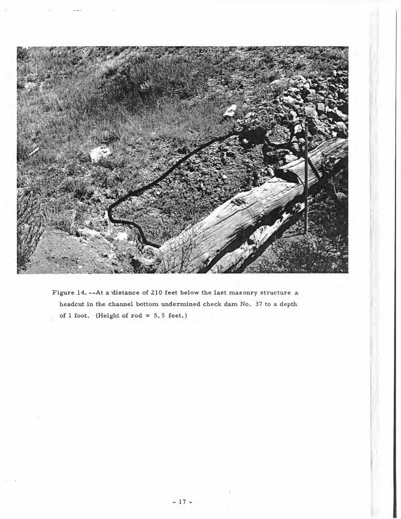
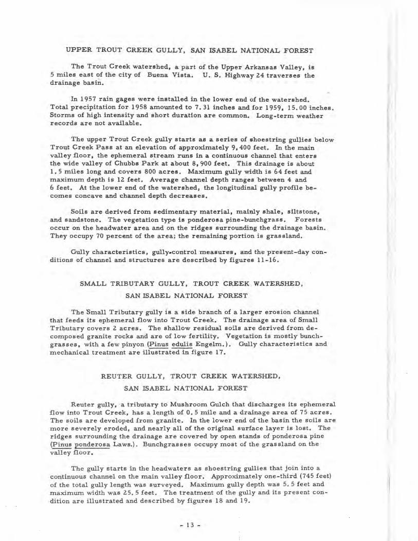
Figure 14. --At a'distance of 210 feet below the last masonry structure a
headcut in the channel bottom undermined check dam No. 37 to a depth
of 1 foot. (Height of rod = 5. 5 feet.)
- 17 -
T
••«»•.-.-rtJT-'V..•'.-.--o**?5*-''/----' ^y £'.,•'*: -:,"'•
Figure 15. —Beginning at the headcut shown in figure 14, channel depth in-
creases rapidly downstream to 12 feet. Structure No. 45, located 490 feet
downstream from the headcut, was undercut like all other dams in this
segment. Cattle still graze the pasture to the left of the gully, but cattle
grazing on the right bank was halted 22 years ago. The left bank is eroding
faster than the right. (Height of rod = 5. 5 feet.)
-^ . • ' • . . . . * •
- 18 -
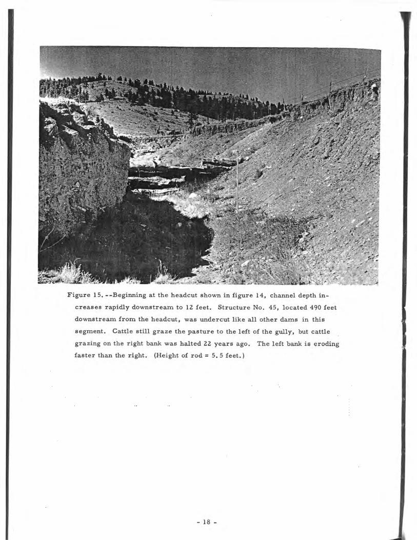
Figure 16. --Half a mile downstream from the headcut in figure 14, the gully
becomes concave and gully depth decreases. Three V-shaped log dams
were installed in this channel reach. Dam height equaled or exceeded
channel depth, and the structures pointed downstream. Small spillways
were provided in the center of the structures. All three dams lost their
effectiveness when the two wings of the dam were pushed apart by the
impact of a flash flow.
- 19 -

Figure 17. --Small Tributary gully is 377 feet long. The channel gradient
averages 31.5 percent. The average channel cross section, computed
from the cross sections at the structural sites, is 11.3 square feet;
2. 3 feet is the average gully depth. Loose-rock check dams were in-
stalled in the 1930's. The average spacing between the dams is 21 feet.
Fifteen of the 18 check dams restricted all the flow; none failed.
- 20 -
•: .
• . , . • v -- -.-- >•
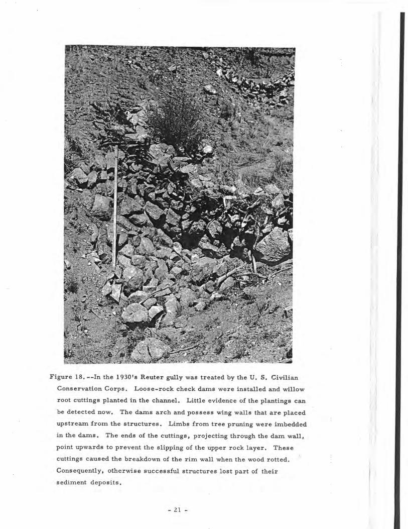
Figure 18.—In the 1930's Reuter gully was treated by the U. S. Civilian
Conservation Corps. Loose-rock check dams were installed and willow
root cuttings planted in the channel. Little evidence of the plantings can
be detected now. The dams arch and possess wing walls that are placed
upstream from the structures. Limbs from tree pruning were imbedded
in the dams. The ends of the cuttings, projecting through the dam wall,
point upwards to prevent the slipping of the upper rock layer. These
cuttings caused the breakdown of the rim wall when the wood rotted.
Consequently, otherwise successful structures lost part of their
sediment deposits.
- 21 -
I

Sediment deposits 7 Check dam
Theoretical extensionof sediment deposits
Gully bottom'
Figure 19. --The spacing of check dams was based on the head-to-toe rule.
However, fewer dams would have been needed if they had been placed at
the expected upstream toe of the deposits.
P R I N C I P L E S O F G U L L Y C O N T R O L
CLASSIFICATION OF GULLIES
The investigation of gullies in the Colorado Front Range indicates thattwo types of gully systems exist. This finding coincides with the gully classi-fication of Leopold and Miller (1956) that was established in a study of gulliesnear Santa Fe, New Mexico. Figures 20 and 21 show the characteristics of adiscontinuous gully system and a continuous gully as examples of the two types.
MECHANICS OF GULLYING
The mechanics of gullying can be explained by hydraulic regimen. Lackof appreciable runoff during the period of this investigation prevented quanti-tative analysis of hydraulic factors. Conclusions drawn from this investiga-tion are reached inductively, supported by observations as found in the fieldand by previous research dealing with gully hydraulics (Leopold and Miller,1956).
The upper segment of the Nursery gully system indicates that a discon-tinuous gully system may become a continuous one (fig. 20). Small headcutsin the upper reach of the lower segment show that this part had its origin in aseries of individual gullies. No evidence could be found that showed the devel-opment of the lower channel reach. It is not known whether the characteristicsof gully formation are different for a discontinuous and a continuous system.This knowledge would be of great importance to gully erosion control.
- 22 -

Profile of original valley
Gully bottom
Figure 20. --This is a longitudinal profile of the upper segment of the Nurserygully system at the Manitou Experimental Forest. It consists of several in-dividual discontinuous gullies. This system is characterized by (1) pronouncedheadcuts in the valley floor that mark the beginnings of individual gullies;(2) rapidly decreasing channel depth downstream; and (3) fans of sediment atthe gully mouths. The slope of a discontinuous gully is always less than theoriginal valley slope. Accelerated erosion advances and the distance betweenthe gullies decreases until one continuous channel is established. In the drain-age segment illustrated, the headcuts of the individual gullies are still visiblein the channel, and channel depth is still decreasing rapidly. The fans belowthe individual gullies are obliterated by gully fusion, but a larger fan developedat the mouth of this system.
L l : : ,
Profile of original valley
Gully bottom
Figure 21. --This profile shows the lower segment of the Nursery gully system.It is a continuous gully. The channel slope approaches the gradient of theoriginal valley floor. The gully starts in the upper drainage without a pro-nounced headcut. Rills and shoestring gullies mark its beginning. It deepensrapidly downstream to a point above the gully mouth. Here, the longitudinalprofile becomes concave and channel depth diminishes until the gradients of theoriginal valley floor and the channel bottom intersect at gully mouth. Belowthe gully mouth, a fan of sediment is formed on the main flood plain.
- 23 -

The longitudinal profile of any gully is the result of geologic and hydraulicfactors. A discontinuous gully grows in both upstream and downstream directionsallowing coalescence of individual gullies to take place. In a continuous gully themost pronounced channel changes occur in the lowest segment above the gullymouth where the difference between channel and valley floor gradient is greatest.
Velocity, width, depth, slope, and roughness parameter have a definite re-lationship to each other for a given flow. Expressed mathematically, the dischargein cubic feet per second equals the cross section of the flow in square feet timesthe velocity of flow in feet per second. This means that if one factor is changed,the others will change also. For example, an increase in roughness results in aslowdown of the velocity. Therefore, to accommodate a certain volume of flow,the gradient has to be increased or the channel increased in depth or width.Whether deepening or widening take place depends on (1) the geologic materials,and (2) the velocity of flow. Both govern the speed of bank and bottom cutting.Generally, both bank and bottom cutting occur at the same time, with one out-ranking the other in magnitude.
If the gradient is changed, a process similar to that in a discontinuous gullyis introduced. A headcut will appear on the channel floor and proceed toward theheadwaters. Thus, the new gradient is carried into the upper channel reaches.
In lower channel segments, headcutting and sediment deposition may counter-act each other. If, for example, sedimentation proceeds upstream with greaterspeed than headcutting in the channel bottom, then an established headcut may beburied. This is of great importance in gully treatment.
At a gully mouth the channel fans out and the flow is distributed at a shallowdepth over a large area. The fan cone with its typical semicircled circumferenceis created by sediment deposits on the main flood plain below the gully mouth.
CRITICAL, LOCATIONS IN GULLY SYSTEMS
From the mechanics of gully development, it follows that there are cer-tain active eroding (critical) locations in a channel. The characteristics ofcritical locations in a continuous gully system differ from those in a discontinuoussystem. Maximum erosion control and minimum costs can be obtained if thecritical locations are treated first.
Since the discontinuous gully is moving in two directions—headcutting up-stream and growth downstream by increase in the gradient—the two main criticallocations are readily detected (see figs. 1 and 2). Also a headcut may developwithin the channel of this system. This phenomenon most likely occurs in longchannels with heavy sediment deposits at the gully mouth.
In a continuous gully the main critical location is the lowest channel seg-ment near the gully mouth where the gradient has not yet reached equilibriumwith the original valley slope. Here, pronounced changes of the channel baselevel take place.
The main critical locations in a gully system are critical (active) by thevery nature of the mechanics of gullying. To achieve an effective gully control,other critical locations caused by meanders with sharp curves, dense brush,tree growth, or other constrictions in the channel should also be consideredfor treatment.
- 24 -
DESIGN OF CHECK DAMS
Hydraulic Requirements
The proper design of erosion-control structures is of great importancefor successful gully treatment. Overdesign results in unjustifiable expendi-tures. Underdesign of one check dam can cause damage to all other installa-tions upstream. This allows accelerated erosion to take place at a rate oftengreater than that in an untreated gully (see fig. 6).
The designer of check dams should consider the highest expected peakflow for the period of treatment. Difficulties in estimating this flow may arisebecause sufficient hydrologic data are not available. Often the designer has torely on high water marks. But his judgment should be supported by experienceand by data that were established under corresponding conditions.
The period of time required for the restoration of a watershed is unpre-dictable. The present investigation illustrates that 20 to 26 years are not suf-ficient to restore the vegetation on the watershed if the vegetal treatment con-sisted of cattLe removal or controlled intensity of grazing only. Sheet erosionstill occurs on the slopes and where control structures failed, gullying continues.
To be successful, a check dam must fulfill certain hydraulic requirements.The cross section of a channel is shaped by the hydraulic factors. Any damchanges the channel cross section and restricts the flow to some extent. Themagnitude of the flow restriction is an important factor to structural success orfailure.
Expected peak flow at the structural sites and discharge capacity of thecheck dams were calculated. From these calculations it was found that no struc-tural failure occurred when the flow was less than 8 c.f. s. (see fig. 17). Withthis volume of runoff the related hydrostatic and dynamic forces are too smallto cause destruction. (Calculations for all of the structures studied are presentedin table 1, page 42.) This condition is represented by Small Tributary gully thatlies in the headwater area of a larger drainage. The expected peak flow wasestimated to be 1 c.f. s. at the gully mouth. No dam failed regardless of whetherit accommodated the flow.
Most log check dams had small rectangular notches in the dam crest (seefig. 14). Since these notches accommodated only a fraction of the total flow, thebulk of the water spilled over the main crest of the dams. Therefore, the in-stallation of notches is not worth while when they possess a discharge capacitysmaller than the total flow.
Check dam No. 22, 15.5 feet long in Upper Trout Creek, represents sucha structure with an insufficient notch. A peak flow of 46 c.f. s. was estimated.The size of the rectangular notch in the dam crest is 0. 3 by 3. 0 feet and itsdischarge capacity about 1.5 c.f. s. Hence, 44. 5 c.f. s. must flow over thedam. Part of the waterfall would hit the unprotected banks because the channelbottom and apron below the dam are only 8. 5 feet wide.
Requirements for the design of check dams to protect the channel belowa structure are demonstrated and discussed in figures 22 through 25.
- 25 -
l -Tv,; '•. 'vf%L-; %y: ',•••.
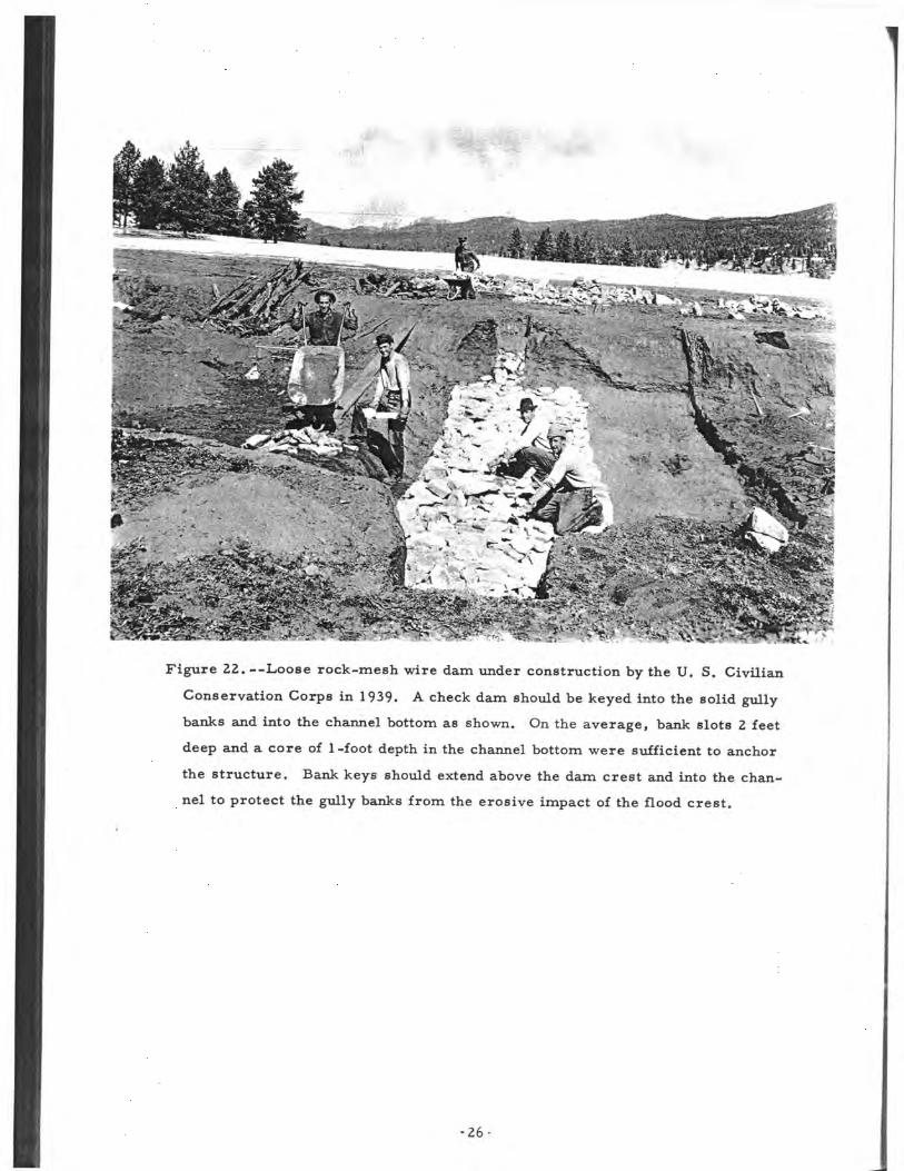
Figure 22.--Loose rock-mesh wire dam under construction by the U, S. Civilian
Conservation Corps in 1939. A check dam should be keyed into the solid gully
banks and into the channel bottom as shown. On the average, bank slots 2 feet
deep and a core of 1-foot depth in the channel bottom were sufficient to anchor
the structure. Bank keys should extend above the dam crest and into the chan-
nel to protect the gully banks from the erosive impact of the flood crest.
•26

Figure 23. —This is the same check dam 20 years later (see fig. 22). It has a
height of 6. 5 feet and an apron length of 6. 5 feet. The apron was effective.
Since the falling water endangers the channel bottom below a dam, an apron
is necessary to dissipate the energy of the water when it reaches the bottom.
Insufficient quality and length of an apron may lead to undermining of the
installation. Bank erosion below the check dam has started because bank
protection was inadequate.
-27-
1
•prEi *•*".? 7 +f tf! gfvffff-t^SxL •''• *> r> . J ; w-Jit
*V' & ,l««fi
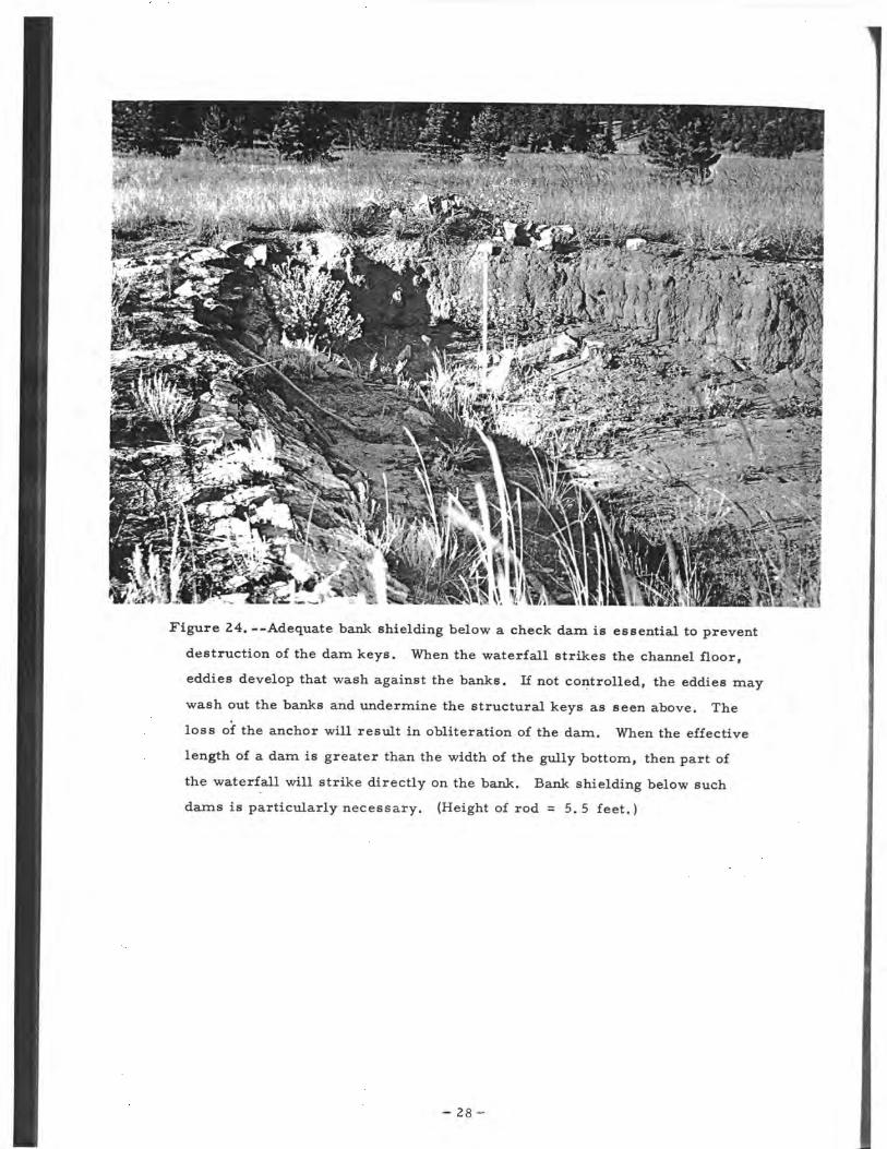
Figure 24. --Adequate bank shielding below a check dam is essential to prevent
destruction of the dam keys. When the waterfall strikes the channel floor,
eddies develop that wash against the banks. If not controlled, the eddies may
wash out the banks and undermine the structural keys as seen above. The
loss of the anchor will result in obliteration of the dam. When the effective
length of a dam is greater than the width of the gully bottom, then part of
the waterfall will strike directly on the bank. Bank shielding below such
dams is particularly necessary. (Height of rod = 5 . 5 feet.)
- 28
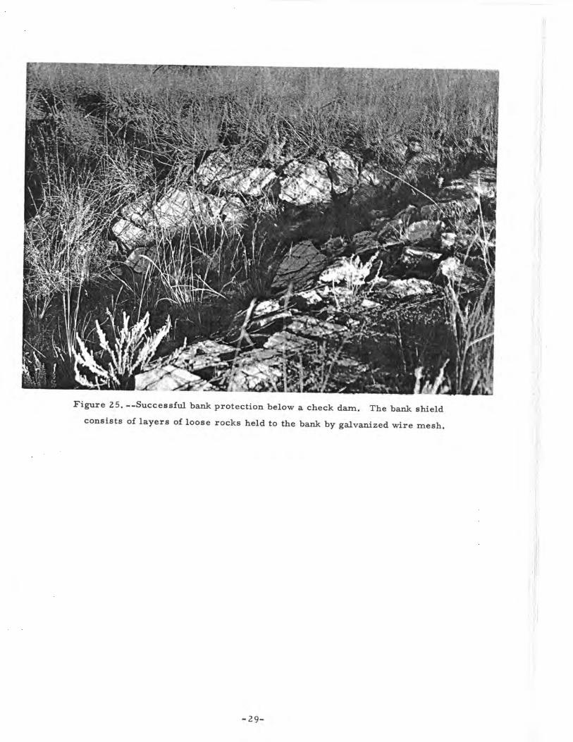
Figure 25. --Successful bank protection below a. check dam. The bank shield
consists of layers of loose rocks held to the bank by galvanized wire mesh.
-29-

Most check dams represent rectangular or trapezoidal weirs. Thedesigner of a dam should select weir dimensions that will accommodate themaximum expected flow. The cross section of the weir may be smaller indepth and greater in length or vice versa. The ratio between length of weirand resulting maximum head of flow will affect the height of the dam. Ingeneral, with increasing weir length and decreasing weir depth the height ofthe dam may be increased. Height determines the depth and the extent ofthe sediment accumulations upstream from the structure.
The depth of the sediment deposits at a check dam and their extensioninto the upper channel reach are important in the stabilization of a gully.These criteria are fundamental to the placement of check dams as discussed inthe following section.
Placement
Check dams were spaced in the gullies by the head-to-toe rule. Thus,in channels with steep gradient many structures were needed. Often they werenot more than 15 feet apart, with average height of 2 feet.
In general, sediment deposits accumulated by a dam possess a gradientgreater than zero. If check dams are installed by the head-tp-toe rule, then theupstream movement of the sediment deposits may be stopped by the upper struc-ture. Thus, the application of this rule may lead to overdesign and the capacityof check dams is not fully utilized.
Overdesign in the spacing of dams is displayed by Reuter gully (see fig. 19).Since sediment deposits are 1 to 2 feet deep at the lower toe of the dams, thestructures could have been placed farther apart. It appears doubtful that damsat the upper toe of all sediment deposits were needed. Certainly, fewer checkdams would, have stabilized the gully.
Where the magnitude of runoff and sediment production is small, as inthe upper reaches of a watershed, the installation of numerous check dams isnot justified. Small Tributary gully represents such a headwater area (see fig. 17),
Overdesign can be prevented by placing the structures where they areneeded and where greatest benefit can be expected. These are the critical loca-tions in a gully system. If additional check dams are needed, structural spacingshould be determined by the expected length of the sediment deposits. Wherethere is not a sudden change in grade between the gradients of the deposits andthe channel above it no check dam will be required to protect the upper gullybottom.
The gradient of the deposits above structures 2 to 3 feet high ranges be-tween 5 and 6. 5 percent in Reuter gully. The original channel gradient is 9. 5percent. Here, the gradient of the deposits is roughly half that of the channelgradient.
Construction Materials
The quality of the construction materials influences the design and themaintenance of control structures. Materials that require continued mainten-ance, such as unpreserved wood, should not be used. In gullies with ephemeralflow, the wood is submerged for short periods of time only. Therefore, it rotsrapidly (see fig. 7).
- 30 -
Selection of construction materials should be based on the importancethat a particular structure has in a gully system, on the magnitude of the ex-pected flow, -and on cost.
In general, the volume of the flow and its related hydrostatic and dynamicpressures are greatest at the gully mouth. Therefore, the most solid structurewithin the system is needed there. If this dam fails, then all structures in thegully may be destroyed by a new erosion cycle.
The lowest segment of the continuous Nursery gully illustrates reoccur-rence of gully erosion caused by the failure of the dam at gully mouth. Thisdam was weaker than those installed upstream (see fig. 3). As a result of thestructural failure, a new channel gradient was established that lowered thegully base level for 650 feet upstream. The headcut undermined four checkdams and is still active (see fig. 21).
Most successful materials for check dams were steel, masonry, andloose rocks reinforced by galvanized woven wire. Gabion-type structuresproved to be highly successful (fig. 26).
PROTECTION OF GULLY BANKS
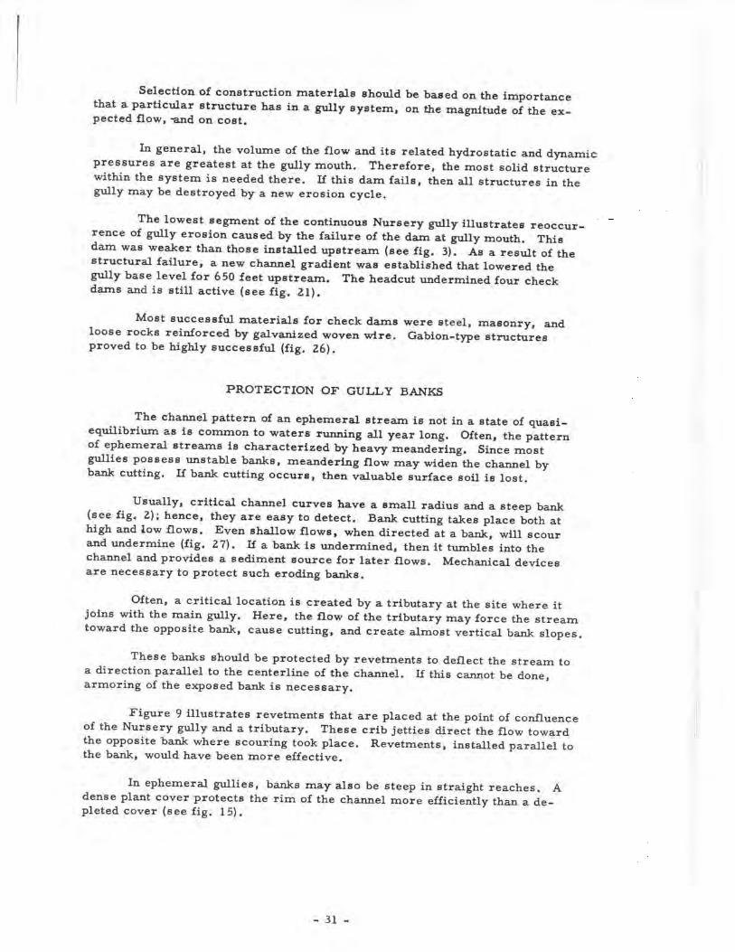
The channel pattern of an ephemeral stream is not in a state of quasi-equilibrium as is common to waters running all year long. Often, the patternof ephemeral streams is characterized by heavy meandering. Since mostgullies possess unstable banks, meandering flow may widen the channel bybank cutting. If bank cutting occurs, then valuable surface soil is lost.
Usually, critical channel curves have a small radius and a steep bank(see fig. 2); hence, they are easy to detect. Bank cutting takes place both athigh and low flows. Even shallow flows, when directed at a bank, will scourand undermine (fig. 27). If a bank is undermined, then it tumbles into thechannel and provides a sediment source for later flows. Mechanical devicesare necessary to protect such eroding banks.
Often, a critical location is created by a tributary at the site where itjoins with the main gully. Here, the flow of the tributary may force the streamtoward the opposite bank, cause cutting, and create almost vertical bank slopes.
These banks should be protected by revetments to deflect the stream toa direction parallel to the centerline of the channel. If this cannot be done,armoring of the exposed bank is necessary.
Figure 9 illustrates revetments that are placed at the point of confluenceof the Nursery gully and a tributary. These crib jetties direct the flow towardthe opposite bank where scouring took place. Revetments, installed parallel tothe bank, would have been more effective.
In ephemeral gullies, banks may also be steep in straight reaches. Adense plant cover protects the rim of the channel more efficiently than a de-pleted cover (see fig. 15).
- 31 -
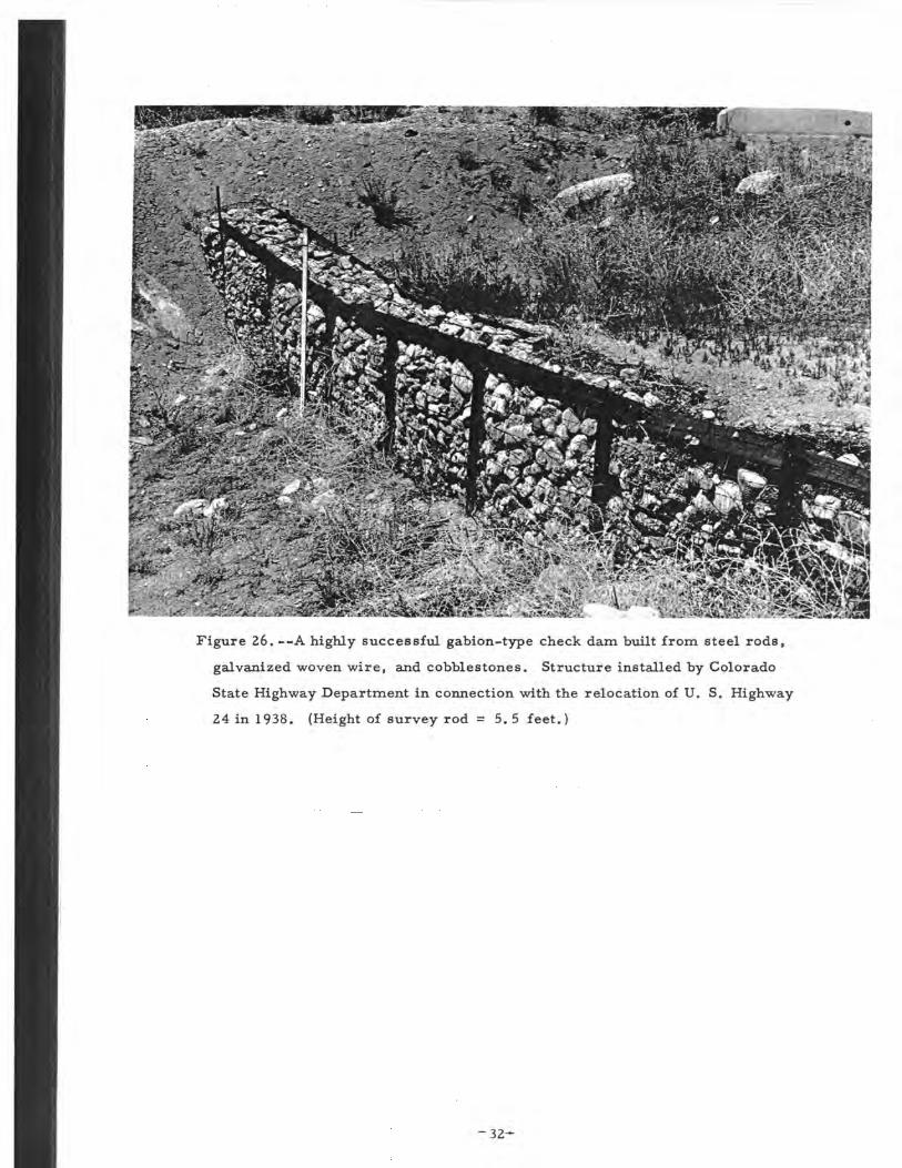
Figure 26. --A highly successful gabion-type check dam built from steel rods,
galvanized woven wire, and cobblestones. Structure installed by Colorado
State Highway Department in connection with the relocation of U. S. Highway
24 in 1938. (Height of survey rod = 5 . 5 feet.)
-32-

Figure 27.—
Flows with shallow
depth undermine
gully banks.
Nursery gully,
Manitou Experi-
mental Forest.
(Height of rod =
5.5 feet.)
In most ephemeral gullies, mechanical shielding of extensive bank seg-ments is not feasible. Here, other measures such as short-grass lining shouldbe applied. Ree and Palmer (1949) demonstrated by experiments that shortgrasses controlled bank and channel-bottom erosion very effectively.
Since vegetation cannot be established on vertical slopes, banks withsteep slopes should be brought to an angle of repose where channel depth isnot excessive. This measure was performed successfully in upper TroutCreek gully where the gully was continuous and banks were less than 5 feethigh (see fig. 12).
The grading of banks may be deferred until the channel bottom is raisedby sediment deposits that accumulate above check dams. Then, steep bankscan be sloughed to an angle of repose without enormous losses of surface soil.
- 33 -

PLANTINGS
Willow and locust were planted at check dams and throughout the gully inthe channel bottom. Survival of the locust was poor, and they did not migrate.Willow plantings had excellent survival. However, willows can cause difficul-ties in gully stabilization. Plants and branches float downstream, take root,and start dense, new stands where obstruction to waterflow is undesirable(see fig. 10). Choking of channels with willows may cause undercutting ofbanks and widening of gully bottoms.
As a general principle, woody vegetation should not be established withinthe high water channel where obstruction of flow would cause the stream to goout of banks or undercut gully walls. When trees and shrubs are planted aroundwings of check dams and at the top of gully banks, care should be used. Speciesthat will not spread to the moist sites along the channel or to sediment accumu-lation areas should be selected.
TREATMENT OF GULLY SYSTEMS
Four gully systems were investigated. The Nursery gully system con-sists of two parts that differ distinctly. The upper segment is a discontinuoussystem; the lower segment is a continuous system. Continuous gully systemswere also studied at the Trout Creek watershed.
The mechanics of gullying in a discontinuous and a continuous gully systemare different. A discontinuous gully tends to expand upstream and downstream.Its critical locations are at gully headcut and at gully mouth. Main structuresshould be placed at these locations.
In a continuous gully, the main active (critical) location is the lowestsegment near the gully mouth. There, changes in channel gradient take placeand, if not controlled, may lead to further channel deepening of the whole sys-tem. Consequently, a main structure is needed at the gully mouth.
Critical conditions in other channel segments may be produced by restrict-ing flow. Flow restrictions occur if the channel cross section is reduced todimensions that do not accommodate a stream of a given velocity. Then, asaccelerated erosion takes place gullies widen, deepen, or both. Trees andshrubs should not be established in a gully if flow is likely to be restricted.
To be successful, the design of a check dam should also comply with thehydraulic requirements of the channel. Following principles were established:
1. A check dam should accommodate the highest expected peak flowfor the period of treatment.
2. A check dam should be keyed in the channel bottom and into thechannel banks.
3. Sufficient structural bank protection and adequate channel floorprotection below a dam is needed.
4. Adequate construction materials should be used.
- 34 -
The extension of the sediment deposits above a check dam depends onthe gradient of the channel, the velocity of the flow, the specific weight, theshape and size of sediment particles, and on the height of the dam. Undergiven channel and flow conditions, the sediment accumulations will extendfarther upstream from a higher installation than from a lower one. Whenthe new channel gradient is established, a critical location may occur at itsupper end and the new slope may be carried into the headwaters by headcuttingof the channel floor. This action is most likely to take place if a pronouncedbreak in grade exists between the slope of the sediment deposits and theconnecting channel segment above.
This new critical location should be determined before the new baselevel is established. Plant and soil conditions vary greatly in a watershedand conditions in ephemeral gullies change from storm to storm and evenduring the course of a flow. Extension of sediment deposits above a damcannot yet be calculated because of insufficient knowledge of the interactingvariables. Meanwhile, empirical data from similar field conditions shouldbe used.
The mechanical treatment of a gully should continue over a period oftime. The first step is to install check dams at critical locations and treatcritical banks. After treatment, periodic inspections are imperative todetermine the.need for further installations or repairs.
When check dams have effectively filled with sediment, the streamvelocity will be more rapid than it was during the filling period because thepools behind the check dams act as stilling basins. However, the velocitywill not be so great as it was without structures, and erosive forces will beless. An equilibrium is eventually achieved between the stream velocityand the larger particles that finally form the stabilized bed.
R E C O MM E_N_D A TIP N S
The final objective of all gully control is to stabilize the channel by vege-tation. Often the condition of gullies is such that this objective cannot beachieved directly. Gullies develop steep banks and a vegetative cover cannotbecome established. Incisions in the valley floor are so deep that the groundwater table on the surrounding land is lowered and plant growth is impeded.To create conditions more favorable to the restoration of vegetation, mechani-cal treatment is needed. The specific purposes of this treatment are:
1. To control the channel gradient until channel stabilization byvegetation occurs.
2. To raise the channel base level;
3. To stabilize channel banks.
To help guide future gully control, the following principles andrecommendations are summarized:
1. Determine the type of system, continuous or discontinuous.
2. Determine the critical locations in the gully system.
- 35 -

3. Estimate the highest expected storm runoff for the periodof structural treatment.
4. Estimate the highest expected peak flow at all structural sites.
5. Design structures to accommodate this flow.
6. In discontinuous gully systems,control headcuts and lower channelsegments near the gully mouth by structures. Install water spreadersbelow the system if the lowest gully mouth is not on the main floodplain.
7. In continuous gully systems, start structural treatment at the gullymouth. Place strongest check dam there.
8. Install structures below headcuts located in the channel bottom.
9. Treat critical locations such as sharp curves in meandering gulliesor cutting banks by revetments. Install these devices parallel to thebank.
10. Do not deflect flow toward channel banks.
11. As a general principle, do not plant woody vegetation within the high-waterchannel where obstruction of flow would cause the stream to go out ofbanks or undercut gully walls.
12. Remove boulders, trees, bushes, and other flow restrictions that wouldresult in bank cutting or overtopping of the channel.
13. To reduce the amount of earth movement and surface soil disturbancerequired, defer bank sloping until channel bottom is raised.
14. After treatment, inspect gully periodically to determine needs formaintenance and further control measures.
- 36 -

Bailey, Reed, W., and Croft, A. R.1937. Contour-trenches control floods and erosion on range lands.
Emergency Conserv. Work Forestry Pub. 4, 22pp., illus.
Edwards, J. A.1958. Structures aid gully control. So. Austral. Dept. Agr. Jour.
61: 465-475, illus.
Fox, C. J. , and Nishimura, J. Y.1958. Soil management report, Trout Creek watershed, San Isabel
National Forest, Region 2. U. S. Forest Serv., Denver, Colo.30pp., illus. [Processed.]
Hack, John T.1957. Studies of longitudinal stream profiles in Virginia and Maryland,
U. S. Geol. Survey Prof. Paper 294-B, 97pp., illus.
Happ, Stafford C. , Rittenhouse, Gordon, and Dobson, G. C.1940. Some principles of accelerated stream and valley sedimentation.
U. S. Dept. Agr. Tech. Bui. 695, 134pp., illus.
Hassenteufel, W.1958. Die Pflanze als Bodenfestiger. [The plant as a soil stabilizer.]
Forstwiss. Centbl. 77 (5/6): 129-138, illus.
Ireland, H. A. , Sharpe, C. F. S. , and Eargle, D. H.1939. Principles of gully erosion in the Piedmont of South Carolina.
U. S. Dept. Agr. Tech. Bui. 633, 143pp., illus.
King, Horace Williams.1954. Handbook of hydraulics for the solution of hydraulic problems.
Ed. 4, revised by Ernest F. Brater, 1 v. , illus.New York, Toronto [etc.].
Leopold, Luna B. , and Maddock, Thomas, Jr.1953. The hydraulic geometry of stream channels and some physiographic
implications. U. S. Geol. Survey Prof. Paper 252, 57pp., illus.
and Miller, John P.1956. Ephemeral streams--hydraulic factors and their relation to the
drainage net. U. S, Geol. Survey Prof. Paper 282-A, 37pp.,illus.
Love, L. D.1958. The Manitou Experimental Forest—its work and aims. U. S. Forest
Serv. Rocky Mountain Forest and Range Expt. Sta. Sta. Paper 7(revised), 21pp., illus. [Processed.]
Morris, B. T. , and Johnson, D. C.1943. Hydraulic design of drop structures for gully control. Amer. Soc.
Civ. Engin. Trans. 108: 887-940, illus.
- 37 -

Peterson, H. V.1950. The problem of gullying in western valleys. In Applied sedimentation
edited by Parker D. Trask. pp. 407-434, illus. New York and London.
Ree, W. O., and Palmer, V. J.1949. Flow of water in channels protected by vegetative linings.
Agr. Tech. Bui. 967, 115pp., illus.U. S. Dept.
Retzer, John L.1949. Soil and physical conditions of Manitou Experimental Forest. U. S.
Forest Serv. Rocky Mountain Forest and Range Expt. Sta. 33 pp.,illus. [Processed.]
Rosa, J. M.1954. Guides for program development—flood prevention on small water-
sheds of the Rocky Mountain area. U. S. Forest Serv., Ogden,Utah.. 152pp., illus. [Processed.]
Schiechtl, H. M.1958. Grundlagen der Gruenverbauung. [The fundamentals of plant use for
soil stabilization. ] Mitt, der Forst. Bundes-Versuchsanst.Mariabrunn, 55. 273pp. , illus. Vienna, Austria.
Thornthwaite, C. Warren, Sharpe, C. F. Stewart, and Dosch, Earl F.1942. Climate and accelerated erosion in the arid and semi-arid Southwest,
with special reference to the Polacca Wash drainage basin, Arizona.U. S. Dept. Agr. Tech. Bui. 808, 134pp., illus.
U. S. Forest Service.1936. Handbook of erosion control engineering on the national forests.
Engin. Div. , Washington, D. C. 90pp., illus.
Vanoni, Vito A., and Pollak, Robert E.1959. Experimental design of low rectangular drops for alluvial flood
channels. Calif. Inst. Tech. Rpt. E-82, 122pp. , illus.[Processed. ]
- 38 -
A P P E N D I X
EXAMPLES OF GULLY CONTROL
Three gully systems are selected to demonstrate gully control as pro-posed by this study. One of the systems represents a discontinuous type andtwo are continuous gullies. The latter had been treated by check dams andwillow plantings 20 to 26 years ago. These measures were successful onlyin part because:
1. The critical locations in the system were not recognized;
2. The hydraulic requirements for check dams were disregarded;
3. Inadequate construction materials were used;
4. The adverse effects of willow plantings in the channel were neglected; and
5. No maintenance was applied.
Retreatment is needed to stop reactivated erosion and to preserve the benefitsderived from the first treatment.
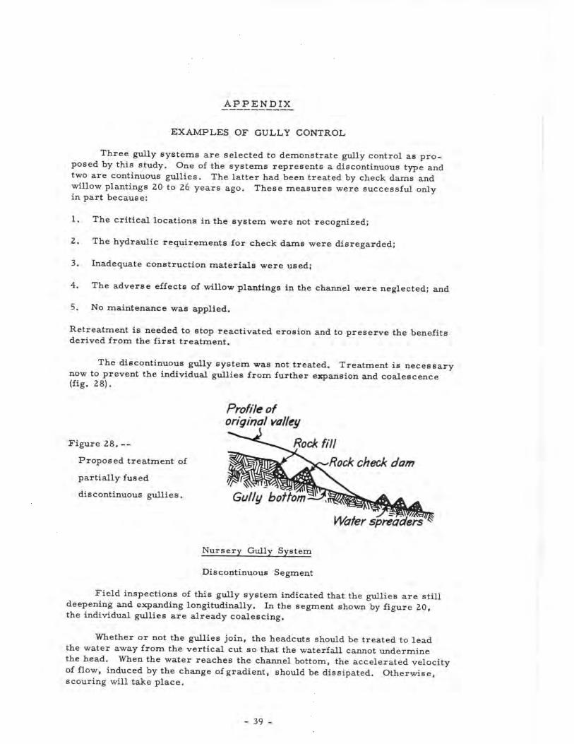
The discontinuous gully system was not treated. Treatment is necessarynow to prevent the individual gullies from further expansion and coalescence(fig. 28).
Prof He oforiginal valley
Figure 28.--
Proposed treatment of
partially fused
discontinuous gullies.
Rock fill
-Rock check dam
Gully bottom
Water spreaders
Nursery Gully System
Discontinuous Segment
Field inspections of this gully system indicated that the gullies are stilldeepening and expanding longitudinally. In the segment shown by figure 20,the individual gullies are already coalescing.
Whether or not the gullies join, the headcuts should be treated to leadthe water away from the vertical cut so that the waterfall cannot underminethe head. When the water reaches the channel bottom, the accelerated velocityof flow, induced by the change of gradient, should be dissipated. Otherwise,scouring will take place.
- 39 -

The segment demonstrated by figure 20 has a, maximum channel depthof 4 feet. It is proposed to use loose rock as the construction material. Theheadcuts will be filled with loose rocks and sloped 1 j : 1 into the channel. Atthe toe of the fill a check dam is needed to stabilize the fill and to dissipatethe energy of the flow. The check dam should possess a discharge capacityat least equal to the estimated peak flow from the design storm.
During succeeding flows, sediment will accumulate above the dam.These deposits will slope gently toward the edge of the headcut and protectthe fill.
Where individual gullies do not fuse, a check dam should be placed nearthe mouth of each gully. The purpose of this dam is to raise the channel gradi-ent to prevent the gully from getting longer.
When individual gullies are in the process of coalescence (see figs. 20and 28), check dams are not needed at the lower ends of gullies, for the headcuttreatment will control the gradient of the upper channel reach.
Below the discontinuous gully system, water spreaders should be installedto prevent the development of a new gully. Spreaders need not be applied betweenthe individual gullies within the system because the water flowing in the channelwill facilitate sediment deposition and vegetative growth.
With the application of these measures, the first phase of gully treatmentis finished. The necessity for additional controls will be determined by futureerosion.
Continuous Segment
The retreatment of this gully starts with the removal of all flow restric-tions such as dams that do not possess sufficient discharge capacity or thathave failed for other reasons, and stands of trees and bushes that choke thechannel and cause undercutting of banks and widening of gully bottoms.
A check dam should be installed at the main critical location near thegully mouth. Here, the sturdiest structure in the system is placed. Checkdams to hold large sediment deposits that are still in place should also bebuilt. For example, at structure No. 10 (see fig. 21) a new check dam isneeded to prevent further headcutting through old sediment deposits.
Critical locations on banks should be protected by revetments installedparallel to the banks. Steep banks should be graded to an angle of repose.This work finishes the first phase of the structural gully treatment.
Upper Trout Creek Gully
The upper segment of the gully is well stabilized by vegetation (see fig. 12)and the deterioration of the log dams does not cause an erosion hazard. Inspec-tion showed that control of the total system may be lost if treatment is notapplied to the main critical location that lies 1.25 miles below this stable seg-ment. Here, check dams failed because of inadequate design and construction(see fig. 16).
- 40 -
When the structures failed, a new channel gradient was carried upstreamby headcutting. This headcut is now 0. 5 mile upstream from the structures thatfailed and 100 feet above the national-forest boundary. While moving upstream,the headcut undermined and destroyed 15 check dams (see fig. 15).
Five masonry spillways, installed above the present headcut, possess anefficient water- and sediment-retarding capacity. Yet, while these structuresslowed down the rate of headcutting, they will not be able to prevent the newgradient from proceeding into the headwaters. If the main critical locationand the headcut are not treated, then these solid structures will eventuallybecome victims of the new gradient. Consequently, a check dam should beinstalled at the main critical location and at the headcut.
Future periodic inspections are needed to determine if and where struc-tures should be placed between the treated critical locations. Their purposewill be to raise the channel base level and hence help stabilize the gully.
G U L L Y S U R V E Y
Kind of structure:
Age of structure:
Success (S) or Failure (F):
Description of structure and channel:
Number:
Date:
Location:
Channel cross section \
Structure cross section \
Weir breadth:
Channel length (structure to structure):
Gradient f[ Old (determined for channel segment):
[ New (present day; between structures):
Sediment trapped V
Soil:
Photograph:
7Parent material:
:
Figure 29. --Sample of field-data form used for surveying and evaluatinggully-control structures.
- 41 -
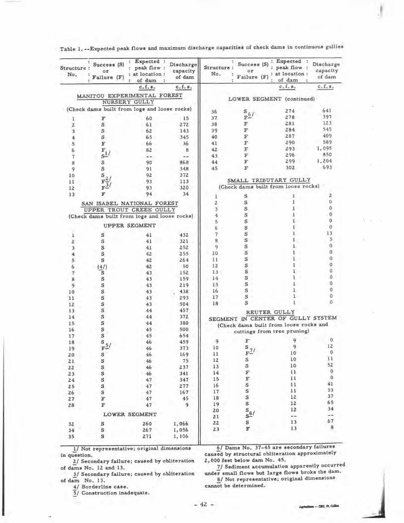
Table 1. —Expected peak flows and maximum discharge capacities of check dams in continuous gullies
StructureNo.
| Success (S) |or
; Failure (F) |
Expected :peak flow :
at location :of dam :c.f.s.
Dischargecapacity
of dam
c.f.s.
MANITOU EXPERIMENTAL FOREST
(Check
123456789
10111213
NURSERYdams built from
FSSsFF
&iSSs,.F-'F—F
GULLY
logs and loose rocks)
606162656682_-909192939394
15272143345
368__
868348372113320
34
SAN ISABEL NATIONAL FORESTUPPER TROUT CREEK GULLY
(Check dams built from logs and loose rocks)
UPPER SEGMENT
123456789
10111213
1516171819202122232425262728
SSSSS
(4/)"sSSSSSs
ssss .F-SSsssssFF
41414142424243434343434344A 1444445454646464646464747474747
432321252255264
50152159219
v 438293504457372380500654459373169
7523734134727716745
9
LOWER SEGMENT
323435
SSS
260267271
1,0661,0561, 106
Structure :No. :
Success (S)or
Failure (F)
: Expected :: peak flow :: at location :: of dam :
c.f.s.
Dischargecapacityof dam
c.f .s .
LOWER SEGMENT (continued)
36373839404142434445
S , .F—FFFFFFFF
274278281284287290293296299302
641397123545409589
1,095850
1,204693
SMALL TRIBUTARY GULLY(Check
123456789
101112131415161718
dams built from loose rocks)
SSssssssssssssssssREUTER
111111111111111111
GULLY
200000
1350000000000
SEGMENT IN CENTER OF GULLY SYSTEM(Check dams built from loose rocks and
cuttings from tree pruning)
91011121314151617181920212223
F
S7/F- .SSFFSSsss
sF
99
10101011111111121212
1313
0120
1152
00
4133376534
678
I/ Not representative; original dimensionsin question.
2_/ Secondary failure; caused by obliterationof dams No. 12 and 13.
3/ Secondary failure; caused by obliterationof dam No. 13.
4^/ Borderline case.5/ Construction inadequate.
6/ Dams No. 37-45 are secondary failurescaused by structural obliteration approximately2,000 feet below dam No. 45.
Tj Sediment accumulation apparently occurredunder small flows but large flows broke the dam.
8/ Not representative; original dimensionscannot be determined.
- 42 - _<3U,n.CollM