Embed Size (px)
Citation preview

A STRUCTURAL MODEL FOR DATABASE SYSTEMS
bY
Gio Wiederhold and Ramez El-Masri
STAN-CS-79-722February 1979
COMPUTER SCIENCE DEPARTMENTSchool of Humanities and Sciences
STANFORD UNIVERSITY


A STRUCTURAL MODEL FOR DATABASE SYSTEMS
Gio WiederholdRamez El-Masri
Computer Science DepartmentStanford University


ABSTRACT
This report presents a model to be uecd for database design, Because our motivation extendsto providing guidance for the structured implementation of a database, we ~11 our model theStructulrJ M&L WC derive the design using criteria of correctness, relevance, and performancefrom semantic and operational specifications obtained from multiple sources These sources typi-crrlly correspond to prospective users or user groups of the database. The integration of suchspecifications is a central issue in the development of an integrated structural database model.
The structural model is used for the design of the logical structures that represent a rcal-world situation. However, it is not meant to represent all po66ible real-world semantics, but asubset of the semantics which arc important in database modclling,
The model uses relations as building blocks, and hence can be considered as an extensionof Codd’s relational model [Codd’lO]. The main extensions to the relational model arc the cx-plicit representation of logical connections between relations, the inclusion of insertion-deletionconstraints in the model itself, and the separation of relations into several structural types,
Connections between relations are used to represent existence dependencies of tuplcs indifferent relations. These existence dependencies arc important for the definition of semantics ofrelationships between classes of real-world entities. The connections between relations arc used tospecify these existence dependencies, and to ensure that they remain valid when the database isupdated. Hence, connections implicitly define a basic, limited set of integrity constraints on thedatabase, those that identify and maintain existence dependencies among tuplcs from differentrelations. Consequently, the rules for the maintenance of the structural integrity of the modelunder insertion and deletion of tuplcs arc easy to specify.
Structural relation types arc used to specify how each relation may be connected to otherrelations in the model. Relations arc classified into five types: primary relations, referenced rcla-tions, nest relations, association relations, and lexicon relations. The motivation behind the choiceof these relation types is discussed, as is their USC in data model design.
A methodology for combining multiple, overlapping data models - also called user viewsin the literature - is associated with the structural model. The database model, or conceptualschema, which represents the integrated database, may thus be derived from the individual datamodels of the users, WC believe that the structural model can be used to represent the datarelationships within the conceptual schema of the ANSI/SPARC DBMS model since it can supportdatabase submodels, also called external schema, and maintain the integrity of the submodels withrespect to the integrity constraint6 CXprC66ablC in the structural model.
We then briefly discuss the USC of the structural model in database design and implementation.The structural model provides a tool to deal effectively with the complexity of large, real-worlddatabases.
We begin this report with a very short review of existing database models. In Chapter 2, WC
state the purpose of the model, and in Chapter 3 WC describe the structural model, first informallyand then using a formal framework based on extensions of the relational model. Chapter 4 definesthe representations WC USC, and Chapter 5 covers the integration of data models that represent thedifferent user specifications into an integrated database model. Formal descriptions and examplesof the prevalent cases arc given.
The work is then placed into context first relative to other work (Chapter 6) and then bricfiywithin our methodology for database design (Chapter 7).


CONTENTS
1. Current state of database models . . . . . . . . . . . .1.1, The relational model . . . . . . . . . . . . . . . .1.2. The hierarchical model . . . . . . . . . . . . . . .1.3. The network model . . . . . . . . . . . . . . . .1.4. Some other models . . . . . . . . . . . . . . . . .
2. Purpose of the structural model . . . . . . . . . . . . .3. The structural model . . . . . . . . . . . . . . . . .
3.1. Real-world structures . . . . . . . . . . . . . . . .3.2. Relations and connections . . . . . . . . . . . . . .
3.2.1. Relations . . . . . . . . . . . . . . . . . . .3.2.2. Connections . . . . . . . . . . . . . . . . . .
3.3. Types of relations . . . . . . . . . . . . . . . . .3.3.1. Primary entity relations . . . . . . . . . . . . . .3.3.2. Referenced entity relations . . . . . . . . . . . . .3.3.3. Nest relations3.3.4, Lexicon relations’
. . . . . . . . . . . . . . . .
3.3.5, Association relations’. . . . . . . . . . . . . . .
3.4. Formal definition of rclatibn’typc6. . . . . . . . . . . . . . . . . . . . . .
3.4.1. Basic relation types . . . . . . . . . . . . . . .3.4.2. Subrclations . . . . . . . . . . . . . . . . . .
3.5. Maintaining the structural integrity of the data model . . .3.5.1. Update constraints in the structural model . , . . , . .3.5.2. Data model update algorithm . . . . . . . . . . . .
3.5.2.1, Tuplc insertion algorithm . . . . . . . . . . . .3.5.2.2. Tuplc deletion algorithm . . . . . . . . . . . .3.5.2.3. Attribute update algorithm . . . . . . . . . . .
4. Representation of data models . . . . . . . . .4.1. Representation of rclationships’in’thb structural model
*. .
4.2. Representation of a relationship between two entity dassc; . .5. Integration of data models . . . . . . . . . . . . . . .5.1. Concepts of integration . . . . . . . . . . . . . . .5.2. Integration of different rcprcscntations of entity classes . . .
5.2.1. Recognition of relations that represent the same entity class5.2.2. Integration of relations that contain different attributes . .5.2.3, Integration of relations that represent different sets of tuples
5.3. Integration of different representations of a relationship , . .5.3.1. Integration with an association . . . . . . . . . . .5.3.2. Integration with a nest of references . , . , , , . . ,5.3.3. Integration with a rcfcrcncc . . . . . . . . . . . .5.3.4, Integration with a nest . . . . . . . . . . . . . .
6, Relationship to other models , . , , . , , , , . , , , ,7. The database design process . . . . . . . . . . . . . .8. Conclusions . . . . . . . . . . . . . . . . . . . .
, * * * . * . . 1, * I * . . . . 1, . , . . . . . 1, . . . . . . l 2, . , l I . L l 2l . . . . . L l 4l . . l . . l . 5, . . . I . * . 5, l , . . . , . 6
. . . l l . , . 8
I l , l , . . . 7, . , . . . . . 9. . . . . . . l 9
. * l . . . l 10, . . . . . . 10, , . . . . . 111 . * . . . . 12, . . . . . . 12l . , . . . . 12, I . . . . . 15* I l . . . l 18* . . . . . . 10. . . . . . . 18l l . . . . L 18* l . . . . . 18. . . . . . . 19. * . . . . . 20l . l l . . . 20. . . . . . . 22, . . l . l . 26* . . . . . . 20. l . . . . . 28. . l . . . . 28. . l . l . . 28, . l * . . . 2 9
l . . . . . . 30l . l . . . . 30, . . . * . . 35, I . . . . . 41, . . . . . . 44I . . I . l . 47. . I . . . . 49, * , * l . . 51


LCURRENT STATEOFDATAMODELS
Database systems have become a major topic of interest because of their widespread use inindustry, commerce, government, and cducetional institutions [Stcc174, Sibleyire, Fry76]. Severaldata models have been proposed to represent the structure of databases. The most widely discussedmodels arc the relational model [Codd’lO], the hierarchical model [Tsichritzis76], and the networkmodel (derived from the CODASYL database system specification [CODASYL74]), The majorityof implemented database systems u6c one of the above models. For an excellent introduction tothese three database models, see [CompSurv78].
1.1. The relational model:
The relational model is formed from relations. Each relation is composed of a set of struc-turally identical tuplcs. Tuplcs arc composed of related data elements. For each relation, a relationdescription, or schema, defines the attributes and the possible values for the data elements that eachtuplc in the relation may take. The sets of tuplcs in a relation is described using the mathematicaltheory of relations, augmented with the concept of functional dependency among attributes. Themathematical basis of the relational model, the uniform representation of all structures as relations,and the syntactic clarity of the data model schema provide important advantages for model andquery analysis.
The relational model ha6 been subjected to intensive theoretical scrutiny. Third normalform [Codd72], and Boyce-Codd normal form [Codd74] have been defined to design relations withfavorable update properties. Bernstein [Bcrnstcin75] describes an algorithm for synthesis of thirdnormal form relations from functional dependencies. Fagin Fagin introduced multivalued dc-pcndcncics and a fourth normal form for relations to extend the understanding of the logi& designof relational databases.
When relations arc built solely from the functional or multivalued dependencies among allattributes in the data model, several possible logi= data models can be derived [Bernstcin75,Fagin77, Chang78, Dclobc178]. Further, 6omc of the data models will not have a direct corrcspon-dcncc with the actual real-world situation being modcllcd [Schmid75]. Then the database designer,or some automatic procedure, ha6 to choose the most suitable model,
A drawback of the basic relational model is that known relationships among entities of thesituation being model arc not explicitly represented but have to be recognized at query processingtime by matching attributes that have the same domain. This requires recognition of similardomains, using the schema, as well as some computation within the database to match data clc-mcnts. Also, logical integrity constraints arc not defined within the model, but arc left to be definedby the database implementors. In one approach, integrity constraints arc described by assertions[Stoncbrakcr74, Eswaran751.
1.2. The hierarchical model:
The hierarchical model represents classes of entities and hierarchical relationships amongdifferent entity classes. A class of cntitics is represented as a record type, and the hierarchicalrelationships arc represented by a tree Etructurc, with record types as nodes in the tree. The recordtype represents the attributes of a class of entities, while each record represents a particular entityof the class, and is composed of data items that describe the entity.
Each record is owned by only one record of the record type at the level above it in the tree,and can own in turn any number of records of the record types below it, if any. Many real worldsituations arc naturally hierarchical, and arc thus well represented by a hierarchical model. In
1

particular, individual user views, or dirta models, ara often hierarchical. Databases used by multipleusers often need a more complex model. In the hierarchical model, non-hierarchical relationshipsarc represented in an awkward and non-symmetric fashion by defining dupliatc record types andusing pointers.
1.3. The network model:
The network model allows representation of non-hierarchical relationships among entityclasses. A record type may be owned by more than one record type, leading to a network reprcscntation of relationships among entity classes. This permits a direct representation of m:nrelationships among entity classes. The concept of a link-set between two record types is introduced.
* A link-set groups together records of ona record type, the member record type, that arc owned bya particular record of a different record type, the owner record type. Existence dependencies togovern occurrcnccs of owner and member records of a link-set arc specified by different types oflink-sets, such as manual and automatic.
The database administrator may specify the access structure used for implementing a link-set as a chain of pointers, a pointer array, or he may specify that the records be stored physi-llyadjacent, Thue acccs6 to the records in a particular link-set via the owner record cBn be veryefficient. However, the database designer has to recognize and define the link-set and its acccs6structure a priori, and queries based on structures not directly implemented may be quite costlyt0 prOCC66.
A drawback of the network model is that only implemented relationships can be exploited,and that, due to implementation constraints, certain relationships arc difficult to express (6uch a6recursive sets [Taylor’lS], which are relationships between records of the same record type). Anothercriticism is that it is too implementation oriented, and thus provides limited data independencepnglcs69J.
1.4. Some other data models:
The problems with the relational, hierarchial and network models have led to active researchin data models. Chang [Chang78] has dcvcloped an approach with a ‘database skeleton” whichincludes semantic information about the relationships bctwccn database relations, and defines therelationships over a time frame using the concept of the “state” of the database. The semanticinformation is used by the system in query translation, and incomplete or “fuzzy” queries maybe processed. Manachcr [Manachcr75] differentiates relationships into several semantic categories.Abrial [Abria174] goes further by distinguishing every relationship according to its particularsemantic notion, but states that his model would bc too complicated for database construction.
Chcn [Chcn’lB] has proposed a model based on the relational model which clearly distinguishesrelations into two types: entities and relationships among the entities. Integrity rules for logicalconsistency arc considered for the relation types, but arc not part of the model. Schmid andSwenson [Schmid75] develop the semantics of the relational model, and show that, in the contextof their model, relations in third normal form can be differentiated into five semantic types. Rulesfor insertion and deletion of tuplcs arc given.
More recently, models have been introduced that provide a more detailed semantic descriptionof the situation being modcllcd [Smith77, Hammar78, Navathc78]. In these papers, constructs arcintroduced to represent subsets of entity classes in the data model, These subsets have a semanticsignificrrncc in the data model, such as certain identifying properties that make them differentfrom other entities in the class,
2

The requirement to have a model which describer the data rclationahip6 independently ofimplementation concerns wa6 recognized when standardization of the CODASYL model wa6 sug-gested. The ANSI/X3/SPARC committee [Steel751 her described a DBMS architecture in rcsponacto the perceived long range needs, A principal component of the architecture is the concept VIschema, which is to contain essential information about the database itself. The conceptual sch&awould be augmented by an internal schema to define the implementation, and by poseibly severalexternal cchcmac to represent the transformations of the database to the views desired by theU6Cr6.

2,PURPOSEOFTHESTRUCTURALMODEL
The numerous data models presented in the literature have given insight into the process oflogical data model design, and the implemented relational, hierarchical and network database eye-terns have provided experience on both logical and physical database design and implementation.The model presented here is intended to assist in the development of a conceptual data model indc-pcndcnt of any implementation, but also to provida a framework for database implementation. WC
propose that the model sotisfics the criteria (Kent771 for representing the relationships within theconceptual schema of a database system that has an architecture similar to the ANSI/X3/SPARCDBMS architecture.
The structural model which WC present here:(1) avoids the storage structure dependency and the limitations of the hicrarchial and network
models,(2) introduces semantic information to the relational model by the representation of logical
connections between relations which also define structural integrity constraint6 in the modelitself,
(3) allow6 a prccirc representation of the semantics of relationships between entity classce, and(4) provides a framework for the design of a database system starting with the design of in-
dividual users data models, to the integration of the data models to form a global databaecmodal, and finally the guidance of the choice of database implementation structures.
Associated with this structural model is a methodology to combine multiple, related datamodels to form an integrated database model, and to design the data models to match closely thereal-world situation being rcprcscntcd. The individual data models also allow the user to specify6omc of hi6 requirements of the database system.
The model WC present is built from relations, augmented with two additional basic concepts.First WC associate a relation type with each relation. Second WC associate connection types with therelation types which dcfinc the structural integrity of this relation with respect to other relationsthat arc logically related to it in the model. WC define structural integrity to be the maintenanceof a consistent relationship among tuplcs in different relations of the data model as defined by theconnections among relations.
During the design and integration process, the relations will be manipulated. To a66urcmanipulatability, WC require all relations to be in Boyce-Codd normal form. However, it is notnecessary to build the relations from the functional dependencies between attributes. Rather, asalso argued by Chcn [Chcn76], if WC first define the logical entities and rClatiOn6hip6 from the rcal-world, then simple transformations will crcatc a model whcrc all relations arc in third normal form.Once a relation is defined with all its attributes, one can check the functional dependencies betweenthe attributes of the relation. If a relation is not in third normal form, it may be transformed intotwo or more relations in third normal form [Wicdcrhold77, scc.7.2]. The structural model prC6CribC6how the data model relation and connection types will represent the entities and relationships ofa particular real-world situation,represent a real-world situation.
and hancc limits the number of possible data model6 that may
WC note here that the structural model is completely independent of implementation con-siderations. While the structural modal does represent connections between relations, it does notmandate implementation of these connactions, Rather, the connections arc used for definitionof 6omc logical integrity constraints, An implementation can be chosen based upon an existingrelational, hierarchical or network database management system, or possibly by u6ing 6ome otherapproach.
4

3,THESTRUCTURAL MODEL
3.1, Real-World Structures:
A database system is used to model some aspect of the real world. People approach real-worlddata in several phases. First, they observe the situation and collect existing data that describethe situation. Then, from their observations, they classify the data into abstractions. Next, theya66c66 the value of their abstractions in terms of how much it helps them manage the world with aminimum of exceptions. Finally, if they have to implement a system, they describe the real-worldsituation by a data model, Such a model may be stored on some physical medium (computer orpaper files), and used as a guide for data processing. WC hence introduce a model which can beused to represent the majority of real-world situations rather than a model which may be used torepresent all po66iblC real-world semantics.
The main building blocks of the data model arc &SW of entitk, such as PEOPLE, CARS,HOUSES,. . . etc. An entity class is described by the primitive components that arc used to describeeach of it6 members, the pmperties. For example, the entity class CARS can have the propertiesLICENSE-NUMBER, COLOR, MODEL, YEAR. The properties that identify a specific entitywithin the entity cla66, in this case the single property LICENSE-NUMBER, arc called the t-t.&q~properties. The properties that describe characteristics of an entity, in this case COLOR, MODEL,and YEAR, arc called the dependent properties.
Associated with each property is a domain, the set of values the it can take in any of theentities that have this property. Some properties may bc repeating. For example, consider the classof entities EMPLOYEES. One of the properties we may represent is the SALARY-HISTORY ofan employee. Each employee will have several entries of the salary history, one for each salary hehad during hi6 previous employment period. The number of cntrics is variable from one employeeto the next. The SALARY-HISTORY is also an example of a anrqwund property, one which isformed of several, more basic, other properties. In this case, SALARY-HISTORY is formed fromtwo more basic attributes, YEAR and SALARY-VALUE. However, such compound properties canalways be decomposed into several of the basic properties,
WC also have to model the relationships that exist bctwccn entity classes. A &zt;onship is amapping among classes. Thus, a relationship defines a rule associating an entity of one class withentities of other (not ncccssarily different) classes. Most relationships WC encounter arc between twoentity classes. An example of such a relationship is CAR:OWNER between the entity classes CARSand PEOPLE. Such relationships may bc 1:l (for example COUNTRY:PRESlDENT), l:N (for cx-ample MANAGER:EMPLOYEE), or M:N (for cxampla STUDENT: CLASS). Other relationshipsmay be among more than two classes. For example, the relationship SUPPLIER:PART:PROJECTis among three entity classes SUPPLIERS, PARTS, and PROJECTS.
A relationship between two entity classes has two important characteristics: the cardinalityand the dependency . The c&in&v of a relationship places constraints on the number of cntiticeof one class that cBn be related to a single entity of the other class. The dependemq characteristicof a relationship places constraints on whether an entity of one class cBn exist that is not relatedto any entities of the other class. WC will discuss these characteristics more fully in section 4.1.
Finally, some classes of entities may be sub-classes of other entity classes, For example, theentity class EMPLOYEES is a sub-class of the entity class PEOPLE.
The data model should rcflcct the real-world structure as closely as possible. This makes iteasier for the u6cr6 to understand the model, and allows useful semantic information from the realworld to be included in the data model.
5

In the structural model, relations arc used to represent entity classes, and some types ofrclationehipe between entity classes, Other relationships between entity classes arc represented byconnections between relations. Relations will be categorized into several types, according to thestructure they represent in a data model. Connections bctwccn relations will also be classified intotypce, and possible connections between relation types arc a part of the model.
Simple properties arc represented by attributes of relations. WC will always dccompoeccompound properties into the simple properties from which they arc formed.
3.2. Relations and Connectione:
Relational concepts arc well known, but for conciseness we now define relation6 and relationschemes a6 WC use them in the structural model. Then WC formally define the concept of connectionsbetween rclatione.
In order to define a relation, we first define attributes, tuplcs of attributes, and relationschemes. Relation schema6 specify the attributes of a relation. Attributes define the domain6 fromwhich data elements that form the tuplcs of the relation an take values.
WC will use B, C, D, to denote single attributes; X, Y, 2, to denote sets of attributee; b, c,d, to denote values of single attributes; and, x, y, z, to denote tuples of sets of attributes. Forsimplicity, WC assume that all sets of attributes arc ordered.
3.2.1. Relations:
Definition 1: An att6but.e B ie a name associated with a set of values, DOM(B). Hence, atxxlue b of attribute B is an clement of DOM(B).
. For an (ordered) act of attributes Y = (Bl, . . ., Bm), WC will write DOM( I’) to denoteDOM( B1) x . . .w
X DOM(B,), where X is the cross product operation. Hence, DOM( Y) ie the set1,. . #, bm) 1 bi E DOM(Bi) for i - 1,. . ., VTL).
Definition 2: A tuple y of a set of attributes Y = (Bl,. . ., Bm), is an clement of DOM( r).
Definition 3: A &tion txkma,R.,, of order m, m, > 0, is a act of attributes Y - (Bl, . . ., Bm).The t$ation, R, is an instance (or current value) of the relation schema R,, and is a 6Ub6Ctof DOM(YJ
Each attribute in the set Y is required to have a unique name.The set Y is partitioned into two subsets, K and G. The ruliw part, K, of relation
schema Rs is a set of attributes K = (Bi, . . ., Bk), k < m, such that every tuplc y in Rha6 a unique value for the tuplc corresponding to the attribute set K. For eimplicity, WC
as6umc the set K is the first k attributes of Y. The dependent part, G, of relation schemaR., (== Y) is the set of attributes G = Y- K, where - is the set difference operator.
All relations arc in Boyce-Codd normal form. (For definitions of functional dcpcnd-cncy and Boyce-Codd normal form, see section 8.1.)
We will write R[q or R[Bl, . . ., Bm] to dcnotc that relation R is defined by the relationschema Y - (Bl, . . ., B,,J.
Also, K(Y) will denote the ruling part of relation schema Y, and G(Y) will denote the do-pcndcnt part. Similarly, for a tuplc y in relation R, defined by the relation schema Y, k(y) willdenote the tuplc of values that correspond to the attributes K(Y) in y, and g(y) will denote thetuplc of values that correspond to G(Y) in y,
6

A relation R[ r] may have several attribute subsets 2 which satisfy the uniqueness requirementfor ruling part, In the structural model, the ruling part of a relation schema is defined accordingto the type of the relation (see sec. 3.4).
3.2.2. Connections:
We now define the concept of a connection between two relations, then define the types ofconnections that are used in the structural model, A connection is defined between two relationschemes, An instance of the connection exists between two tuplcs, one from each relation.
Definition 4: A wnnectian between relation schemes Xl and X2 is established by two sets ofa~tiw attributes Y1 and Y2 such that:
a. YlCXl.b. Y2 C X2.c. DOM( Y1) - DOM( Y2).WC then say that X1 is connected to X2 through (Yr, Y2).Two tuplcs, one from each relation, arc wnnekd when the values for the connecting
attributes arc the same in both tuples.
The definition of connection is symmetric with respect to Xl and X2, and thus it is anunordered pair.
Connections may be more complex. For example, if WC desire a connection between twosets of attributes with dissimilar, but related, domains, condition (c) above may by changed toDOM( Yl) - f(DOM( Y2)). The function j will relate values of data elements from the two domains.The equality condition in (c) above is the simplest case.
The structural model uses three basic types of connections, which we now define. Associatedwith each of the connection types arc a set of integrity constraints that define the existence dc-pcndcncy of tuplcs in the two connected relations, These constraints define the conditions forthe maintancnce of the structural integrity of the model, We will define structural integrity, anddiscuss these constraints in section 3.5.
Definition 5: A W- wnnedion from relation schema Xl to relation schema X2 through(Yl, Y2) is a connection between Xl and X2 through (Yl, Y2) such that:
a . Y2 - K(X2).b. Yl C K(Xl), or Y1 C G(Xr), but Yl may not contain attributes from both K(Xl)
and G(X1).
Definition Sa: A reference is an identity trjmmx if Yl = K (Xl).
Definition Sb: A reference is a direct e-e if it is not an identity reference.
Reference and direct reference are not defined symmetrically with respect to X1 and X2, andthus arc ordcrcdcd pairs (Xl, X2) when the reference is from Xl to X2. The identity reference isdefined symmetrically, but WC still consider it to be ordered, This is because identity references arcused to represent a subrelation of a relation, defined in section 3,4.2, and WC consider the referenceto be directed from the subrclation to the relation.
Definition 6: An ownc&ip wnnccttim from relation schema Xl to relation schema X3 through(Yl, Y2) is a connection between Xl and X2 through (Yl,Ys) such that:
a . Yl - K(X1).

x2
x2 It--K-----i
(a) Direct reference (Xl, X2) from the ruling part of Xl
x2 I
(b) Direct reference (Xl, X2) from the dependent part of Xl
I Xl
t - - v - l
It - - - 2 - - - i
}~K=-j ~~(c) Identity reference (Xl, X2)
IIt--y2-i
I II 1r------K-------1
(d) Ownership connection (Xl, X2)
b. Y2 C K(X2).
Figure 1. Types of connections
The ownership connection is also non-symmetric with respect to Xl and X2, and is an orderedpair (Xl, X2) when the ownership connection is from Xl to X2.
The connections defined above may be represented graphically as in figure 1. They are represented by directed arcs, with the # representing the &I end of the connection. The ruling partattributes in each relation arc marked K, and separated from the dependent part attributes bydouble lines ( 11).
8

3.3. Type8 of relations:
Relations in the structural model arc classified into structural types, which define their in-teraction with other relations in the data model. Relations can also be classified semanticallyaccording to the concept they represent from the real-world situation. One should be careful todistinguish between the semantic and the structural role of a relation in a data model,
Semantically, WC distiguish between classes of entities, properties of classes of entities, andrelationships among classes of entities. Classes of entities can be represented by several structuralrelation types, depending upon their relationship with other classes of entities. Hence, entity classesmay be represented by either primary entity relations, referenced entity relations, or nest relations,as we shall see.
Non-repeating properties of a class of entities arc represented as attributes of the relationthat represents the entity class. Repeating properties of a class of entities arc represented by anest relation owned by the relation that represents the entity class (see section 3.3.3).
Relationships among entity classes can also be represented using different structures, dcpcnd-ing upon the characteristics of the relationship. A relationship between two entity classes may berepresented by an ownership connection, a reference connection, or two connections and an auxiliaryrelation. This auxiliary relation may be a primary relation, a nest relation, or an associationrelation (see section 4.1).
Structurally, relations arc categorized into five types: primary relations, referenced relations,nest relations, association relations, and lexicon relations. These are all relations which have thesame form, but are classified according to their connections to other relations.
In this section, WC informally present the rationale behind the choice of the different structuralrelation types. WC give formal definitions for the relation types in section 3.4.
A relation in the data model which represents a class of entities in the real-world situationis termed an Mttitv ndcdh The choice of entity classes is a fundamental aspect of the data modeldesign process. The goal is to match entity relations as closely as possible to real-world entityclasees.
Structurally, entity relations may be primary, referenced or nest relations. The choice ofstructural type to represent an entity relation depends upon its role in the data model. In thefollowing three sections, we discuss the criteria for this choice.
3.3.1, Primary entity relations:
An important objective of the data model is to represent real-world entities. The existence ofa tuplc in the data model which represents such an entity is hence determined by the existence ofthe actual entity, independently from other modclling considerations. Classes of such entities arcrepresented in the data model by primary entity relations. Examples of primary entity relationsare EMPLOYEES and CARS, ‘Primary entity relations should be chosen to be update-independentof other relations in the data model. An update of another relation should not require an updateof a primary entity relation. An update of an entity relation, however, may require updates toother relations connected to it, as WC shall see later.
An example of a primary entity relation is the relation EMPLOYEES in a model that rcp-resents a company. Updates to the EMPLOYEES relation occur only from outside the database.An employee tuple is inserted whenever a new employee is hired by the company, and deletedwhenever an employee leaves. This potentially affects several other relations in the database suchas CHILDREN and EMPLOYEES-DEPARTMENT, Thus, insertion of an employee tuplc involvesthe possible addition of tuplcs to other relations in the database that arc connected to the employeerelation, such as tuplcs that represent the employee’s children in the CHILDREN relation, and tuplcsassociating the employee with the departments he works for in the EMPLOYEES-DEPARTMENT
9

relation. Note that the number of additional tuplcs added to the database because of the insertionof a new primary entity tuple is variable, and determined externally; the model only presents theuser with guidelines to follow when inserting a primary entity tuplc.
The deletion of a tuplc from a primary entity relation may imply the deletion of relatedtuplcs from other relations in the database , Thus, the deletion of an employee tuplc will involvethe deletion of tuplcs for his children from the CHlLDREN relation, as well as tuplcs associatinghim with the department he worked in from the EMPLOYEES-DEPARTMENT relation. Sucha deletion does not involve any additional checking before the tuplc is deleted, since a primaryentity relation may not be referenced by any other relation in the data model.
3.3.2. Referenced entity relations:
When representing a real-world situation, one often encounters abstractions that arc usedmainly to describe properties of other entities. Such entities arc referenced by other entities inthe model. This type of entity is a mj$~~Ed entity, and classes of such entities arc representedin the data model by referenced entity relations. Examples of referenced entity relations arcCAR MODEL SPECIFICATIONS, referenced by the attribute MODEL in the relation CARS,and JOB DESCRIPTION, referenced by the JOB attribute of the relation EMPLOYEES. TheUSC of these referenced entities greatly reduces redundancy in the data model. As we shall see, themain difference between a primary entity relation and a referenced entity relation in the structuralmodel is in their update characteristics.
A direct reference connection will exist from some relations in the data model, termed them-w relations, to the referenced entity relation. The reference connection restricts the dclc-tion of tuplcs in the rcfcrcnccd entity relation, as well as the insertion of tuplcs in the referencingrelations. WC di6CU66 these restrictions here in terms of an example, and will define them preciselyin section 3.4.
An example of a referenced entity relation is presented with respect to a company database.Suppose the company wishes to keep track of current and possible suppliers for inventory items.The SUPPLIERS relation is a referenced entity relation. The existence of supplier tuplcs is dctcr-mined by a selection from the real-world, since the company maintains a list of its current andpossible suppliers. However, a supplier tuplc may not be deleted while it is being referenced fromthe INVENTORY relation within the data model. Thus, the deletion of tuplcs from a referencedentity relation requires checking the tuples in all relations in the data model which reference thisreferenced entity relation. Addition of tuplcs to the referencing relation, the INVENTORY relationin this case, is restricted to those tuples that reference an already existing supplier, representedby a tuple in the SUPPLIERS relation in the database. Thus, the name of a supplier for a newinventory item should exist in the SUPPLIERS relation before the new referencing tuplc is addedto the INVENTORY relation.
Tuplcs of referenced entity relations may be referenced from more than one relation. Forexample, the SUPPLIERS relation, may be referenced from the ACCOUNTS-PAYABLE relation,describing unpaid bills, as well as from the INVENTORY relation. Note that supplier tuples mayexist which arc not currently referenced from other tuples in the database, but one mnnot delete asupplier tuple without checking tuples in all relations that may reference the SUPPLIERS relation.
All other update characteristics for referenced entity relations arc the same as the updatecharacteristics for primary entity relations. In the rest of this paper, when WC USC the term entityrelation without qualification, WC will mean primary or referenced entity relation.
~ 3.3.3. Nest relations:
willHierarchical dependencies occur frequently in real-world situations. Hence, real-world entities
be represented in the data modcl whose existence directly depends upon the existence of
10

another entity, For example, in a company database, tht: CHXLDREN relation represents childrenof employees currently working in the company, The existence of children tuplcs in the Companydatabase is justified while their parent works for the company, and the tuplc representing theparent exists in the EMPLOYEES relation. Such entities will be represented in the data model bynest datlima.
A nest relation always COrrcSpOnd6 to a 1:N relationship between two data model relations,the ~wtzet r&at&m, and the nest relation, In our example, the EMPLOYEES relation is said to ownthe CIIILDREN relation, This 1:N relationship is represented in the data model by an ownershipconnection from the owner relation to the nest relation.
For each tuplc in the owner relation, a set of zero or more tuplcs will exist in the nest relationthat arc connected to this tuplc. The cxistcncc of this set of tuplcs depends upon the existence ofthe ~vnrr tuple in the owner relation. The term ‘nest relation has been chosen because each ownertuplc will own a ‘nest’ of tuplcs in the nest relation. The existence of individual tuplcs of the nestis determined by the real-world requircmcnts.
Hierarchical dependencies also occur when a class of entities has a repeating property, wherethe number of rcpctitions is variable for each entity in the class. WC then represent the repeatingproperties by attributes in a nest relation that is owned by the relation representing the entityclase. An example is the cducntion history attributes of on employee in the company database.Here, the EMPLOYEES relation owns the nest relation EDUCATION EIISTORY. In the structuralmodel, the normalization to fir6t normal form forces the USC of distinct nest relations, but theConnection to the owner relation remains recognized.
Insertion of a tuplc in a nest relation is contingent upon the existence of the owner tuplcin the owner relation. Thus, one may not insert a child or an education history tuplc without acorresponding owner employee tuplc in the EhlPLOYEES relation, The deletion of a tuplc froma nest relation is not restricted by the ownership connection. The deletion of a tuplc from theowner relation requires deletion of the nest of tuplcs owned by it in the nest relation. Insertion oftuplcs in the owner relation may involve the creation and insertion of a nest of tuplcs in the nestrelation.
3.3.4. Lexicon Relations:
A l* &&&a is used to represent a one-to-one correspondence between two act6 of at-tributes. Most frequently, the one-to-one corrcspondcncc will bc between only two single attributes,but sets of attributes may also bc involved, Examples are the on&o-one correspondence betweenthe two attributes DEPARTMENT-NAME and DEPARTMENT-NUMBER in a company datamodel, or that between the two sets of attributes (INSTRUCTOR, CLASS, SECTION} and(ROOM, HOUR, DAYS) in a university data model. This one-to-one correspondence reflects asimilar correspondence between properties.
Such one-to-one CorrC6pOndCnCc6 bctwccn two sets of attributes occur frequently, and isolat-ing lexicons simplifies the data model considerably by transferring attributes that serve the samefunction into a lexicon relation. One set of attributes can represent all instances of either setoutside of the lexicon itself. Which set of attributes remains in the core of the data model is leftto the judgment of the model designer.
The lexicon relation will have a reference connection to it from every relation in the datamodel that includes either one or both of the sets of attributes in the lexicon. The referenceconnection may be a direct reference or an identity reference, depending on the situation.
Lexicons 6crvc another important function in the data model, Frequently, relations will havemore than one sat of ruling (or /cq) attributes. A set of ruling attributes is guaranteed to havea unique value for any tuplc in the relation, and thus any such set of ruling attributes may beused for tuplc identification, In our model, each relation has one primary set of ruling attributes,
11

the rulingrelations.
part of the relation. Other equivalent sets of ruling attributes arc transferred to lexicon
The USC of lexicons can greatly reduce the number of possible alternatives for the data model,leading to a significant simplification of the model design process. The two sets of attributes in alexicon relation can be treated conceptually as a single attribute in intermediate procct3sce whichlead to the design of the data model, and can thus bc considered as equivalent in the data model.Hence, lexicon relations can be seen as a means of reducing the number of attributes in the coreof the data model, leading to the creation of a clearer, simpler model,
3.3.5. Association relations:
WC finally consider relations used to represent the interaction between two or more relationsin the data model. Such relations will bc termed oaaociation, ~&ions. An association relation betweentwo relations associates with each tuplc of one relation a number of tuplcs from the other relation(possibly none). It does not rcprcscnt any existence dependency between the tuplcs in the differentrelations, but only an association between existing tuplcs.
An association relation of OK&Y i relates tuplcs from i owner relations. Each of the ownerrelations has an ownership connection to the association relation.
An example of an association of order 2 is the relation EMPLOYEE-PROJECT which relatesan employee to the projects he works in, and vice-versa. Each project tuplc and each employeetupla have an existence of their own, independently from the tuplcs in the association relation. Atuple in the association only relates an employee with a project,
An example of an association of order 3 is the SUPPLIER-PART-PROJECT relation, whichrelates tuplcs from three owner relations.
An association relation is used to represent information relevant to a relationship betweenentity classes. Usually, the entity classes arc represented by the i independent relations. Thus, inoujr example, the EMPLOYEE-PROJECT association may include information about the job theemployee does for the project, the percentage of time ho works on the project, . . . etc. It is alsopossible for association relations to have no dependent information. In this ULBC the associationrelation is used only for relating tuplcs from the owner relations together,
The update rules for an association relation and its owner relations are now self-evident: notuplc in the association relation may be created if there arc no corresponding owner tuplcs in theowner relations, and deletion of a tuplc from any owner relation causes the deletion of all tuplcsaffiliated with it from the association. Note that the deletion rule does not affect the existence ofthe tuples related to the deleted tuple in the other owner relations: it only affects those tuplcs inthe association relation that serve to relate these tuplcs together. Thus, deletion of an employeewould not affect the existence of any of the projects hc works for.
3.4. Formal definition of relation types:
In this section, WC formally define the different types of relations discussed in section 3.3 interms of their connections with other relation types in the data model. WC then define 6ubrclation6of existing relations, and how a subrelation is connected to its base relation in section 3.4.2.
For the remainder of the paper, WC will USC the term relation for both the relation schemaand the relation, since the meaning is clear from the context.
3.4.1. Bafic relation type6:
Samantially, relations arc classified into entity and non-entity relations.
12

Figure 2. A nest relation, R2
Definition 7: An mtity t$ation is a relation R[Xj which defines a corrccpondcnce betweenmembers of a class of real-world entities and the tuplcs in R[Xl.
The ruling part of an entity relation defines the correspondence to the class of real-worldentities, while the dependent part includes the attributes that describe basic properties of theentities.
Structurally, WC define five basic types of relations:
Definition 8: A primal dutbn is a relation that has no direct references or ownership con-nections to it from any other relation in the data model.
Primary relations arc required to have no references or ownership connections to them. Thus,deletion of tuplco from primary relations is unconstrained by the data model.
Definition 9: A nzw n&him is a relation which has direct references to it from somerelations in the data model.
The ruling part attributes K(R) fo a referenced relation, R, arc used for referencing R fromother relations. Hence, each relation R’ that references R will have a set of referencing attributesthat define the reference connection to R. This constrains insertion and deletion of tuplcs in bothR and R’.
Insertion of a tuplc in R should prcccdc any reference to it from a tuplc in a referencingrelation. Deletion of a tuplc from R involves checking that it is not referenced by any tuplcs fromany of the relations that reference R. Insertion of a tuplc in R’ requires the existence of all tuplcethat it references.
Definition 10: A n& reiatzbn is a relation, R2, which has an ownership connection to it fromexactly one other relation, RI, in the data model. R1 is the owner of R2.
A nest relation R2 has an ownership connection to it from the owner relation, RI. Hence, theruling part K(R2) will consist of two parts: a set of attributes to define the connection with RI,and additional attribute(a) which must uniquely identify tuplcs owned by the same owner tuplcin RI.
Insertion of tuplcs in R2 requires the existence of the owner tuplc in RI. Deletion of tuplcsfrom the nest relation may occur based on conditions determined externally from the database,but may also be the result of deleting an owner tuplc from RI, which requires deletion of all tuplceowned by it in R2.
13

t--K--1
RI IIR2R,
l - - W - l FF2-i
FK+Figure 3, An association relation, R, of order 2
Figure 4. A lexicon relation, R[Xj
Definition 11: An tmuc&ation rekation R of order i, i > 1, is a relation R that has i ownershipconnections to it from i other relations in the data model, RI,. . .Ri cuch that:
a. each Rj has an ownership connection to R through Xi, Yj for j - I,. . .i.
b. YinYk=$for j#k.
c. K(R) -YlU*aeUYin
An association relation of order i has i ownership connections to it, one from each of thei owner relations. Hence, the domain of the ruling part attributes of an association relation is awtcnation of i acts of attributes, each set defining the connection to one of the owner relations.A tuplc in the association is owned by one tuplc from each of the owner rclatione. For each tuplein an owner relation, there may exist zero, one or many owned tuplcs in the association.
Deleting a tuplc from an owner relation will thus require the deletion of all tuplcs owned byit in the association, Insertion of a tuplc in the association will require the existence of the i ownertUplC6.
Definition 12: A k&wn r$atirm R[Xj between two acts of attributes Yl and Yg defines a I:1correspondence between DOM( Yl) and DOM( Y2) such that:
a. Y1 - K(X).b. the set of attributes Y2 does not appear in any relation other than R.c. Yl n Y2 - 0, and Yl (J Y2 - X.d. R is referenced by one or more relations in the data model by identity or direct
references.
14

A lexicon will hove reference connections to it from all the relations in the data model thatcontain the set of attributes in the lexicon. The ruling part of a lexicon is the attribute set that existsin the other relations in the model, and the dependent part is the other attribute act in the lexicon.For example, if it is necessary to identify the dapartmcnt in several relations of the data model,then either DEPARTMENT-NUMBER or DEPARTMENT-NAME would be chosen. To simplifythe model, an arbitrary single choice is made, say to USC the attribute DEPARTMENT-NUMBERin all relations of the model. Then, DEPARTMENT-NUMBER will be the ruling part of thelexicon, and DEPARTMENT-NAME will be the dependent part. Every relation containing theattribute DEPARTMENT-NUMBER will reference the lexicon.
The above definitions define the five structural types of relations: primary, referenced, nest,association, and lexicon. Connections can exist at any level in the model: nest relations can beowned by other nest relations, by associations, or by referenced entity relations as well as byprimary entity relations. Similar choices exist for referenced relations, associations, and lexicons.A subrelation may be defined on any relation. In the following section, WC define subrclatione.
~ 3.4.2. Subrclationo:
A subrclation S of some relation R defines a subset of the tuplcs in R as belonging to thesubrelation, This subset of tuplcs either has a semantic significance in the data model, or hascertain additional properties that have to be represented, but that arc not represented in the othertuplce in R. The relation R is called the hue &tion of the subrclation S.
I .
WC will not allow duplication of information in the representation of a subrclation, otherthan the information needed for tuplc identification, Hence, a subrclation will have the same rulingpart attributes as the base relation, and will be connected to the base relation through an identityreference connection. The identity reference reflects the fact that a tuplc in the subrelation thathas the same value for the ruling part as a tuplc in the base relation represents the 8amc entityin the data model.
All attributes other than the rulingfrom the attributes of the base relation.
part attributes of the subrelation have to be different
Definition 13: A (non-restriction) edndAbn of relation R[Xj is a relation S[q such that:a. an identity reference exists from S to R.b. for every tuplc z in S, there exists a corresponding tuplc x in R such that k(x) -
k(Z)*c. z-K(z)r)X-K(x)=B.The relation R is called the base relation for subrelation S.
Definition 13a:A d&&n Whtion of a relation R[Xj, restricting the act of attributes Y,Y C X, to the subdomain D, D C DOM(Y), is a subrclation S[a of R such that: forevery tuple x in R that has as value for the set of attributes r a tuplc y in D, thereexists a corresponding tuplc z in S such that k(z) - k(x).
An example of a restriction subrelation is a relation TECHNICAL EMPLOYEES, a subrela-tion of the EMPLOYEES relation, restricting the attribute JOB of EMPLOYEES to the subdomain{engineer, researcher, technician}, say.
Existence of tuplcs in a restriction subrclation is totally dependent on the existing tuplcs in itsbase relation. In our example, all employee tuplcs with job value engineer, researcher or technicianmust also exist in the TECHNICAL EMPLOYEES subrelation, while all other employee tuplcscannot exist in this subrelation.
An example of a non-restriction subrelation is a relation EMPLOYEES IN SPECIAL PROJECTX. Existence of tuplcs in this subrclation is determined externally of the data model, but confinedto tuplcs in the base relation of all employees.
15

WC will USC subrelations to represent three ca6c6:(1) When a subset of a relation has a semantic significance within the data model, or ha6
additional attributes that riced to be represented in the model.(2) When integrity constraint6 require a 6ub6Ct of a relation to own a nest relation or an
association, or to be referenced from another relation.(3) When WC combine data models to form an integrated database model (see section 5), 6omc
data models may represent 6Ub6Ct6 of relations represented in other data model6 This ha6to be reflected in the integrated database model,
The update rules for the base relation and the subrelation arc: when a tuplc that belongsto the subset represented by the subrelation is inserted in (deleted from) the base relation, thecorresponding tuplc (having the same ruling part value) is inserted in (deleted from) the subrcla-tion. Also, if an update to a tuplc in the base relation results in the removal of the tuplc fromthe BUbGCt, the corresponding tuplc should be deleted from the subrclation. For example, if thejob of an employee tuplc is changed from engineer to manager the corresponding tuplc in theTECHNICAL EMPLOYEES subrclation should bc deleted.
3.5. Maintaining the structural integrity of the data model:
Structural integrity exists in our model when the tuplcs in the data model do not violate theconstraints specified by the connections bctwccn relations, One cBn consider that the structuralmodel contain6 a basic set of integrity assertions as part of the model. The integrity assertionsarc those Cxprc66cd implicitly by the connections between rclatione, and arc used to specify theexistence dependencies, and hence the update constraints, of tuplcs in connected rclatione.
WC do not specify in the model when or how the integrity constraints arc to be maintained inan implementation of the data model, The purpose of the model is that integrity constraints canbe recognized, and that implementors can refer for guidance to the model. In practical implcmcn-tations, there may be intervals where the structural integrity rules do not hold. It should be knownhowever which structural integrity constraint6 have been violated and arc awaiting correction.Hierarchical and network databases tend to require that all integrity constraints be satisfied forthose connections that arc actually implemented. Techniques dealing with temporary integrityviolation6 using artificial reference tuplcs arc indicated in [Wicdcrhold77].
Our model may appear less powerful than the original relational model since update integrityviolation6 cBn occur, In the pure relational model, inter-relation connections arc not described, butarc left to be discovered at query-processing time. The lack of recognition of logi= connectionsbetween relations in a database model will simplify certain tcchnial problems during update,but doe6 not eliminate semantic inconsistencies relative to knowledge models of the database ad-ministrator or the u6cr. Furthermore in many situation6 it is best to discover and correct integrityviolation6 at the time of update rather than to try and cope with an inconsistent database at queryproccseing time.
In section 3.54 WC list the integrity constraint6 specified by each connection type, then give asummary of rules for maintenance of the structural integrity for each of the relation types. WC thenshow in section 3.5.2 how these rules may be cxprC66ed a6 simple algorithm6 for maintaining thestructural integrity of the database upon insertion and deletion of tuplcs, and update of attributevalues.
3.5.1. Update constraints in the otructurol model:
The integrity constraints specified by the connection types arc the following:A direct nzjkrence crmnectin from relation R.1 to relation R2 specific6 the constraints:
(1) Every tuplc in R.1 must reference an existing tuplc in R2.
16

(2) Dcletion is restricted for tuplcs in R2. Only tuplcs that arc not rafarcnced from any relationin the data model may be deleted.
An eume&&ip a~~ne&m from relation R1 to relation R2 spccifice the constraints:(I) Every tuplc in R2 must be owned by an existing tuplc in RI.(2) Deletion of a tuplc from R1 requires deletion of all owned tuplcs in R2.
An identity refermcc aonnacfion from a subrelation RI to it6 base relation R specifics the con-etraints:(1) Every tuplc in RI must reference an existing tuplc in R.(2) Deletion of a tuplc from R requires dclction of the rcfercncing tuplc in RI.(3) If RI is a restriction subrelation, then every tuplc in R that belongs to the subrelation
(specified by the value of the restricting attributes in R) must exist in RI,
WC now give an informal listing of the update constraints associated with each relation type:1. Primary relation:
(a) The tuplcs arc neither owned nor referenced by other tuplcs in the data model.(b) Deletion of a tuplc requires the deletion of tuplcs owned by it in nest and aesociation
relations.(c) Insertion of a tuplc requires the existence of referenced tuplcs in the relations referenced
by attribute values in the new tuplc.
2. Referenced relation:(a) The tuplcs arc referenced from other tuplcs in the data model.(b) The ruling part defines the attributes through which the fuplce are referenced by other
tuplcs in the data model.(c) Deletion of a tuplc is constrained by the existence of references to that tuplc. Also, a6 in
w(d) A6 in l(c)
3. Nest relation:(a) The tuplcs may be referenced from other tuplcs in the data model.(b) The ruling part defines a specific owner tuplc, and a specific tuplc within the nest of tuplcs
that ha6 the 6amc owner tuplc.(c) A6 in l(b). If the relation is referenced, deletion is constrained by existence of references
to the tuplc.(d) Insertion of a tuplc requires the existence of the owner tuplc in the owner relation, and the
existence of referenced tuplcs in relations referenced by it.
4. Lexicon relation:(a) A6 in 2.8.(b) The ruling part is a set of attributes, through which the tuplc ie referenced.(c) Deletion of tuplcs is constrained by the existence of reference6 to that tuple.(d) Inecrtion of a tuplc requires no checking.
5. A66datiOn relation of order i :(a) A6 in 3.8.(b) The ruling part defines i specific owner tuplcs, one from each of the i owner relations.
17

(c) A6 in 3.~.(d) Insertion of a tuplc requires the existence of the i owner tuplcs in the i owner relation, and
the existence of referenced tuplcs in relations referenced by it.
6. Subrelation:(a) A6 in 3.8.(b) The ruling part attributes arc used for referencing the base relation through an identity
reference.(c) A6 in 3.~.(d) Insertion and deletion of tuplcs in a restriction subrelation arc totally controlled by existing
tuplcs in the ba6c relation.
As indicated earlier, a relation may have more than one connection with other relations inthe data modal. A nest relation may for instance itself be referenced, and may also reference tuplcsof another referenced entity relation. In these cases, all connections impose constraint6 on the datamodel.
3.5.2. Data model update algorithms:
WC now give three simple algorithm6 for maintaining the structural integrity of the datamodel by observing the constraints given in the preceding section. The algorithm6 will be describedin terms of the connection type6 defined in section 3.2.2.
3.5.2.1. TupJc insertion algorithm:
Upon receipt of a request to insert a new tuplc x in relation R:a. Check the consistency of the new tuplc with the current tuplcs in the database:
8.1. For every relation RI referenced by R through a reference connection, verify thatthe tuplc y referenced by x exists in RI.
a.2. For every relation RI that has an ownership connection to R, verify that the ownertuplc y of x exists in Rl.
b. If the new tuplc is consistent with the data model, insert it and for every relation R2 ownedby R through an ownership connection, send a message to the u6cr reminding him to insertthe tuplcs owned by x in R2.
Thus insertion involves two actions: checking that tuplcs connected with the new tuplc existin the data model, and insertion of other tuplcs connected with the new tuplc. The checking canbe done automatically, but insertion of other new tuplcs will in most ~86~6 be done by the u6cr.For example, the insertion of an employee tuplc involves insertion of his children in a nest relationCHILDREN owned by the EMPLOYEES relation, and of the tuplcs associating the employee withthe department he work6 for in the EMPLOYEE-DEPARThlENT association relation, also ownedby EMPLOYEES, However, any new tuplcs in both CHILDREN and EMPLOYEE-DEPARTMENTarc inserted by the u6cr. The system only reminds the user that such data may exist, and if theydo exist they should bc added to the data model.
In 6omc ca6c6, a6 when a nest relation represents repeating properties of an entity class, anapplication program cBn be written to insert all properties of the entity simultaneously. Both atuplc in the entity relation, and it6 nest of tuplcs that represent the repeating property arc inserted.
3.5.2.2. Tuplc deletion algotithm:
Upon receipt of a request to delete tuplc x in relation R:.
18

a. Check for direct references to x from other tuplcs in the data modal: If relation R is areferenced relation or a lexicon, check that x is not referenced by any tuplc from a relationwith a direct reference to R. If x is referenced, send an error mcBsagc, and do not completethe deletion,
b, Check if tuplcs owned by x may be deleted: For every relation RI owned by R, initiatedeletion of the tuplcs in RI owned by x. For every subrelation R2 of R, initiate deletionof the tuplc y in the subrelation that corresponds to x.
C. If all the owned and subrelation tuplcs can be deleted, complete deletion of x. Otherwise,do not complete deletion of x, and send a warning message that x could not be deleted,
Deletion also consists of two parts: checking that the tuplc being deleted is not referenced,and deleting tuplcs owned by the tuplc being deleted. The algorithm io rccureivcly applied.
3.5.2.3. A ttributc update algorithm:
Upon receipt of a request to update attribute A of tuplc x, which belongs to relation R:a. If A is neither an attribute through which R references other rclatione, nor a member of
the ruling part of R, perform the update.b, Update of connection attributes:
b.1. Referencing attributes: If A is an attribute through which R references a relationRI, check that the new value will reference an existing tuplc in RI. If the newvalue references a non-existing tuplc in RI, do not complete the update and fendan error message.
b.2. Ruling part attributes: If A is a member of the ruling part of R, initiate deletion ofx using the deletion algorithm. Xf deletion is completed, insert the updated tuplexl with the new value for A using the insert algorithm. Otherwise, send an errormcs6agc *
19

4,REPRESENTATIONOFDATAMODELS
WC now present the guidelines that the structural model presents to a data model designer,and di6CU66 how a choice is made between the different representation form6 provided by the struc-tural model to represent a particular situation. We will see that the same data can be representedwith different relationships, according to the situation, or the view of the data model designer.Eventually such differences cBn be accomodatcd in the integrated database model.
WC u6c the following notation to represent connections in our diagrams:
I?->A
Ownership connection Direct reference Identity reference
41. Representation of relationships in the structural model:
One of the advantages of the structural model is that it guides the choice of representation fora particular situation. Thie is because the rules attached to each relation and connection type arcexplicit, and will lead the data model designer to mrcfully consider the situation he is modclling.A model relevant to the real-world eituation will be the result, and the situation will be clearlyrcprcecntcd.
In the ensuing discussion, WC USC the term relationship to denote a relationship between tworeal-world entity cla66c6, and the term connection to denote a connection between two relationsin B data model.
. consider the relationship between two entity cla6sc6, FATHERS and CEiILDREN. This is a1:N relationship, and may be represented using several different constructs in the structural model(figure 5):a. A6 an association between two entity relations representing fathers and children.b. A6 a direct reference, from an entity relation representing children, to a referenced entity
relation representing fathers.c. A6 an ownership connection, from an entity relation representing fathcro, to a ncet entity
relation representing children.
The choice among these alternatives depends upon the situation being modcllcd.
First, consider the case where the data model represents a community of people. Each personin the community ha6 an identity of hi6 own, and WC want to represent the father-child rclationehipbetween two persons in the community. In this case, the appropriate representation would be a6an a66ociation between two persons, the FATHER-CHILD association relation (figure 58). If eitherthe father or hi6 offspring move from the community, there is no further need for a father-childconnection between two persons in the community, This is well represented in the data model bythe association, since deletion of a father (or child) tuplc causes the deletion of the associatingtuplc, but leave6 the tuplc representing the other person unaffected.
On the other hand, cupposc the data model represents data from a school system. In thisca6c, the father-child relationship is best represented by a reference connection from a CHILDRENrelation to a FATHERS relation (figure 5b). This restricts the deletion of a father tuplc a6 longas it is being referenced by a child tuplc. Again, this is a faithful representation of the situationeince WC want to keep information on the father a6 long a6 ha ha6 a child in the school. Also, every

(a) Auociation (b) Reference (c) Nest
Figure 5. Some representations of the FATHER:CHILD relationship
1 SUPPLIERS t
I I I1 SUPPLIERS-PARTS-PROJECTS j
1 PARTS-PROJECTS 1
(a) A66OCiatiOn (b) Ncet and association
Figure 8. Some representations of the SUPPLIERS:PARTS:PROJECTS relationship
child in this school must have 6omc information about hi6 father. (If the father is unknown, an“unknown father” tuplc could be placed within the FATHERS relation.)
Finally, if the data model represents data from a ampany, and a child is represented in thedata model only because hi6 father works for the company, then the relationship is best representeda6 a nest relation CHILDREN owned by the FATHERS relation (figure 5~). (In this ca6c, FATHERScould be a eubrclation of the EMPLOYEES relation.) Then, children arc automatically deletedfrom the data model once their father is deleted. Here, when an employee is fired (and the decisionis made to remove hi6 representation from the active employees file), the company is not interestedin any information about hi6 children.
Let is consider a second example, that of an inventory allocation. The situation being rcp-resented is the association between suppliers, parts and projects, If each of the three entity classesha6 an independent existence of its own, the appropriate representation is an association amongthree entity relations SUPPLIERS, PARTS and PROJECTS (figure 6a).
Alternatively, suppose that WC want to associate with each supplier the part6 that he supplies,60 that a part does not have an independent existence, but depends on the supplier that supplies thepart. Then, the situation is best represented by two entity relations, SUPPLIERS and PROJECTS,a nest entity relation PARTS owned by the SUPPLIERS relation, and an association relationPARTS-PROJECTS between PARTS and PROJECTS (figure 6b). Note that this represents thefull association of SUPPLIER:PART:PROJECT, since by the definition of a nest relation, theruling part of the nest relation PARTS includes the ruling part of the SUPPLIERS relation (6ccsection 3.4.1).
These two examples show how the update rules a66oCiatCd with each relation type arc usedfor guidance when designing a data model. The update rules force the data model designer tocarefully consider the characteristics of the situation that he is modclling, and thue the data modelbecomes a faithful representation of the situation.
21
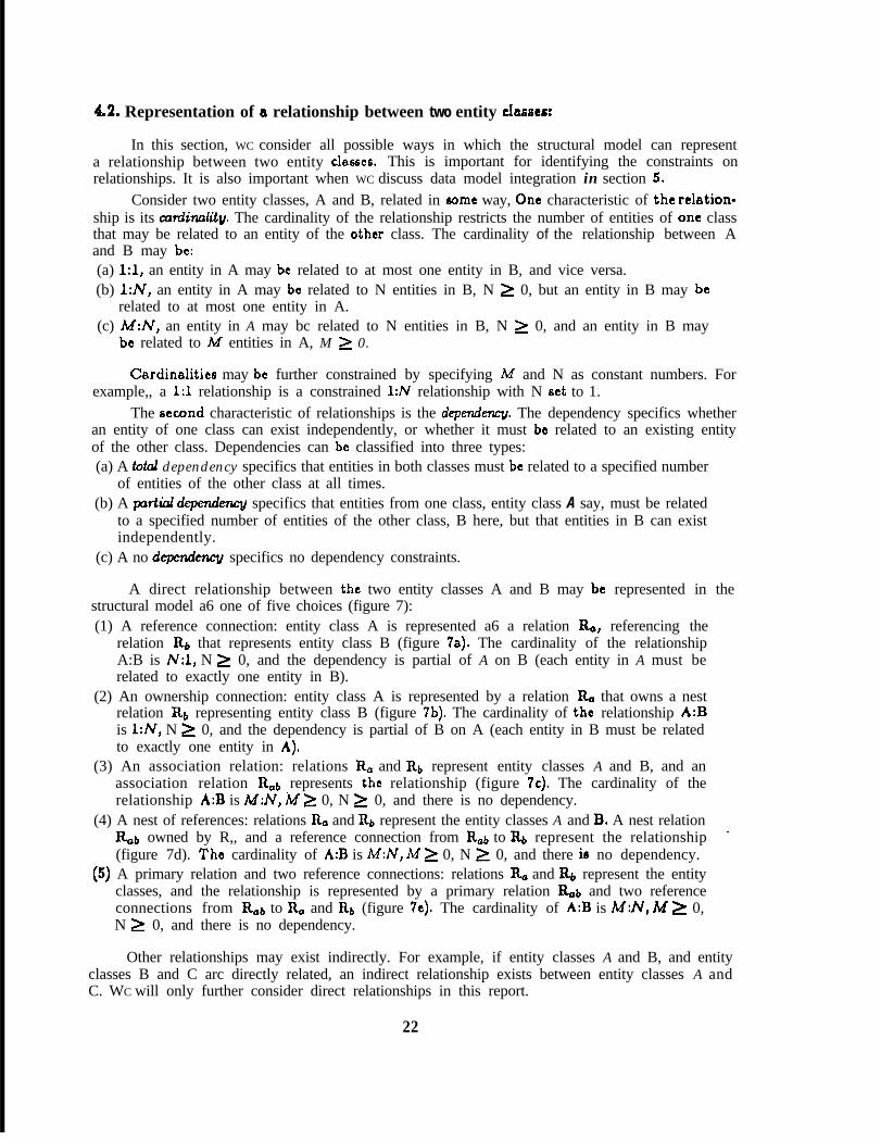
42. Representation of a relationship between two entity classes:
In this section, WC consider all possible ways in which the structural model can representa relationship between two entity clesscs. This is important for identifying the constraints onrelationships. It is also important when WC discuss data model integration in section 5.
Consider two entity classes, A and B, related in some way, Onc characteristic of the rclation-ship is its amiinulity, The cardinality of the relationship restricts the number of entities of one classthat may be related to an entity of the other class. The cardinality of the relationship between Aand B may be:(a) 1:1, an entity in A may be related to at most one entity in B, and vice versa.(b) l:N, an entity in A may be related to N entities in B, N > 0, but an entity in B may be
related to at most one entity in A.(c) M:N, an entity in A may bc related to N entities in B, N > 0, and an entity in B may
be related to M entities in A, M > 0.
Cardinalitics may be further constrained by specifying M and N as constant numbers. Forexample,, a 1:l relationship is a constrained 1:N relationship with N set to 1.
The second characteristic of relationships is the dependenq. The dependency specifics whetheran entity of one class can exist independently, or whether it must be related to an existing entityof the other class. Dependencies can be classified into three types:(a) A totd dependency specifics that entities in both classes must be related to a specified number
of entities of the other class at all times.(b) A partial depend- specifics that entities from one class, entity class A say, must be related
to a specified number of entities of the other class, B here, but that entities in B can existindependently.
(c) A no depmzcletzcy specifics no dependency constraints.
A direct relationship between the two entity classes A and B may be represented in thestructural model a6 one of five choices (figure 7):(1) A reference connection: entity class A is represented a6 a relation R,,, referencing the
relation &, that represents entity class B (figure 78). The cardinality of the relationshipA:B is N:l, N > 0, and the dependency is partial of A on B (each entity in A must berelated to exactly one entity in B).
(2) An ownership connection: entity class A is represented by a relation R, that owns a nestrelation R+ representing entity class B (figure 7b). The cardinality of the relationship A:Bis l:N, N > 0, and the dependency is partial of B on A (each entity in B must be relatedto exactly one entity in A).
(3) An association relation: relations R, and Rb represent entity classes A and B, and anassociation relation Rtlb represents the relationship (figure 7~). The cardinality of therelationship A:B is M:N, M > 0, N > 0, and there is no dependency.
(4) A nest of references: relations R. and Rb represent the entity classes A and B, A nest relationRab owned by R,, and a reference connection from &b to Rb represent the relationship -(figure 7d). The cardinality of A:B is M:N, M > 0, N > 0, and there ie no dependency.
(5) A primary relation and two reference connections: relations R, and Rb represent the entityclasses, and the relationship is represented by a primary relation Rob and two referenceconnections from Rob to R, and Rb (figure 7~). The cardinality of A:B is M:N, M ) 0,N > 0, and there is no dependency.
Other relationships may exist indirectly. For example, if entity classes A and B, and entityclasses B and C arc directly related, an indirect relationship exists between entity classes A andC. WC will only further consider direct relationships in this report.
22

(a) Referenceconnection
(b) Ownership (c) Associationconnection relation
(d) Nest ofreferences
(c) Primaryrelation
Figure 7, Representing two directly related entity classco
Data models that represent the same two related entity classes may USC different rcprc-scntations for the relationship according to the way they view the update constraints. Tworeasons for choosing different representations can be distinguished: difference in understandingand difference in representation. WC illustrate the differences with an example.(I) The two data models differ in their understanding of the 6amc real-world situation, Consider
the two entity classes DEPARTMENTS and EMPLOYEES. It is possible that one userassumes that the relationship between DEPARTMENTS and EMPLOYEES is 1:N (eachemployee work6 in only one department). A second user is aware of exceptions and con-siders the relationship M:N (an employee may work in more than one department). Adisagreement exists here about the actual situation being modcllcd, and one of the datamodels is in error, It may be that the first user knows only about employees that workin one department, If such a conflict occurs between the two data models, the real-worldsituation being modcllcd must be rc-examined to determine its actual characteristic& WC
will not consider this problem further.(2) The two data models represent the real-world situation differently, each user choosing the
representation which best suits his integrity control requirements. consider the DEPART-MENTS and EMPLOYEES example, and suppose the relationship is of cardinality 1:N.It may be represented in one of the following ways, among others:
(a) a reference connection from EMPLOYEES to DEPARTMENTS (figure 8a), .
(b) an ownership connection from DEPARTMENTS to EMPLOYEES (figurer 8b,8c),(c) an association relation restricted to 1:N (figure 8d),(d) a nest of references from EMPLOYEES to DEPARTMENTS (figure 8~).
The different representations reflect different integrity requirements:
The reference representation requires each employee represented in the data model to belongto a department, and restricts deletion of a department from the data model while it isreferenced by 6omc employee,
The ownership connection representation also requires that each employee belongs to adepartment, but that deletion of a department tuplc from the data model results in thedeletion of all the employee tuplcs who work in that department.
The association does not place any constraints on the existence of the actual entities represented, the employee and department tuplcs. However, an association can exist onlybetween tuplcs represented in the data model.
Finally, the nest of references restricts the deletion of a department while referenced by6ome employee, but allows employee tuplcs to exist in the data model that arc not relatedto any department.
23

[EMP-NO 11 A G E ISAL~DEP-NO ~--->IDEP-NO 1jLocl
(a)Rcfcrcncc connection
[DEP-NoIEMP-N~/~ AGE~SAL]
w(b)Nest with unique employee identification
[DEP-N0 II Lot I
rDEP-NOIEMP-IDiAGEkAL 1
(c)Nest with non-unique employee identification
1 D E P- N O 11 LOC 1 1~~~440 11 AGE 1 SAL 1
\ /[DEP-N~]EMP-N~[
UJ)(d)Association
1 EMP-NO 11 AGE t SAL 1
*[EMP-NO]DEP-NOf-->[DEP-NOIILOC]
(U)(c)Nest of references
Figure 8. Different representations of the DEP:EMP 1:N relationship
Since the association representation cBn be used to represent M:N relationships, but here theDEP:EMP relationship is l:N,’ the EMP-NO attribute must have a unique value for each tuplc inthe association relation, This is indicated in figure 8d by marking the attribute with a (U). Notethat this does not violate Boyce-Codd normal form.
The nest of references may also represent an M:N relationship, and to restrict it to l:N, WC
also mark the EM&NO attribute in the connecting nest relation by a (U) (figure 8~). WC will USC
this convention throughout the examples in section 5.In the ownership connection representation, WC must consider two cases. The identifying
attribute for each EMP tuplc in figure 8b is EM&NO, and has unique values for each employeeindependent of his department. Hence, WC mark it (U). In figure 8c, the identifying attributes foran EMP tuplc arc the two attributes DEP-NO and EMP-ID, where EMP4.D serves to define theemployee within his department, and hence is unique within a department but is not unique overall cmploycc6.
24

The different vicwo may all be equally valid, and hence more than one sat of views, andcorreeponding rcmantics, has to be retained in the integrated database model 60 that it cBn Bcrvain a variety of situations.
WC now consider the problem of integrating different data models, defined by independent usergroups and applications, into an integrated database model, to be used as the conceptual schema.WC assume a database system architecture similar to that described by the ANSI/XS/SPARCreport.
25

5, INTEGRATION OF DATA MODELS
WC now discuss integration of data modelf. First WC briefly define our terminology for logicaldatabase design.
A DATA MODEL is a representation of the requirements of a particular potential databaseuser group or application. The definition of data models for individual user groups that expect toUSC the database is the first step in the design of an integrated database.
The DATABASE MODEL is the integrated model created by merging the individual datamodels. During merging, differences in view arc bound to appear, The differences may be resolvedby transformations of the original data models, It is possible that unresolvable conflicts will emergeamong the original data models. Then managcmant dCCifiiOn6 have to be made to force data modelchanges, or to abandon the integration with respect to 6omc data models.
A DATAB4sE SUBMODEL is the user or application view that is consistent with the integrateddatabaec model. Hence, if no conflicts occurred between a user data model and the integrateddatabase model, the database submodcl for that user will be the 6amc as the data model. If someconflict had arisen, 6omc differences will exist between the data model and the database submodel.
In section 5.1 WC consider some general concepts of data model integration, and in section5.2 WC consider the integration of relations from different data models that represent the samereal-world entity class. In section 5.3 WC show how to integrate two different representations of arelationship between the same two real-world entity classes.
5.1. Concept8 of integration:
The data models WC integrate will represent real-world situations that partially overlap,otherwise there will be no need for integration. Hence WC expect to discover relations in separatedata models that represent the same entity classes. The first phase of integration is to recognizeeuch relations, This is not always a simple task, since different data models may USC differentnames for relation6 that represent the same entity class.
Recognition of relations that represent the aamc entity class in different data models is basedon matching ruling parts, since the ruling part defines the correspondence to an entity class. Therelation names and the ruling part attribute names can provide an initial hint to such corrcspon-dcnccs. If data exists, similar values within the ruling part attributes can further indicate candidatesfor entity matching, A match or overlap of the domain definition of ruling part attribute6 cBnestablish the necessary equivalence.
Ruling parts may be translated via lexicons, 60 the search for similar ruling parts must alsoconsider lexicons of ruling part6 in the data models. Since lexicons preserve the identity of rulingparts, WC will not specify throughout that lexicons can be used in the matching of ruling parts.Some examples of equivalence through lexicons wil! be given in section 5.2.
WC assume in this report that rigorous definitions exist for the domains that the attributescover. Definition of domains and attribute encoding can be a major effort, but is outside the scopeof this report. This problem is also addressed by people working on the requirements analysisphase of database design.
The second phase of integration, following the recognition of relations that represent thesame entity clasecr, is the recognition of differences in the representations. These differences arcof three types:(1) Representation of different properties of the same entity class. This ie reflected in different
dependent part attributes in the relations that represent the 6amc entity class.
26

(2) Rcprcscntation of different subsets of entities of the same entity class. Thie is reflected indifferent tuplcs in the relations that represent the same entity class,
(3) A combination of (1) and (2).
WC will cover integration of those cases in section 5.2.
The final phase is to integrate the representation of relationships between two entity classes.As shown in section 4.2, there arc five ways to rcprcscnt direct relationships in the structuralmodel. Data models may choose to represent the relationship between the same two entity classesdifferently, according to their view of the situation. Hence, the final phase of integration is tocreate an integrated database model which will support different representations of relationshipsin the data models. WC wvcr this phase in section 5.3.
Many data models may have to be integrated into a single database model. To avoid excessivecomplexity WC will analyze the integration of only two data models in detail. Successive integrationsteps can merge another data model with the database model being built, creating a new databasemodel. Since both data models and database models USC the same primitives, this should not posea problem.
We hence have two data models, data model 1 (dml) and data model 2 (dm2). Both datamodels will include relations that represent some common entity classes, as well as other classesof data. WC only look at one entity class A in section 5.2, and two entity classes A and B witha relationship between them in section 5.3, WC will denote the relations that represent entityclasses A and B in dml and dm2 by R, and Rb. If both representations arc the same, clearly thereis no need for any transformation, and the integrated database modal (idbm) will USC the samerepresentation. If representations differ, WC create an idbm to support both data models.
The idbm will then support database submodcll (dbsml) and database submodcl 2 (dbsm2),corresponding to dml and dm2 respectively. In moat c8aca, dml and dm2 will not be changed, sodbsml and dbsm2 will be equivalent to dml and dm2. In some casea, where conflicts appear, oneof the data models may have to be changed, and the corresponding database submodcl will reflectthose changes. When the database model is established, it may also be desirable for pragmaticreasons to change a database submodcl to achcivc a better agreement with the database.
In some cases, only a subset of the tuplcs in relation R. (or Rs) in the idbm correspond tothe R, (or Rb) relation included in dbsml or dbsm2. WC then USC a subrelation to represent thesubset, and an identity connection will join it to R, in the idbm. For example, if Ro in dbsmlcorresponds to a subrclation of R, in the idbm, WC denote this subrelation by R,l in the idbm, andR,l will have an identity reference to R,. This subrelation &1 of & contains only the ruling partattributes of R,, so that no duplication of information occurs in the idbm. All other attributes in& can be accessed through the identity reference to Roe
WC do not address the problem of authorization of users to perform insertion and deletion.We assume that every databe& submodcl has complete insert, delete, and update authorizationover the part of the database model it represents. Hcncc, if one submodcl, dbsml say, insertsa tuplc that does not violate the integrity constraints of dbsm2, the tuplc is inserted in both ofthem. If the tuplc violates the integrity constraints of dbsm2, it is inserted but remains invisible todbsm2. For deletion, if deletion of a tuplc is legal in dbsml, say, but the tuplc may not be deletedin dbsm2 because of integrity constraints, the tuplc will be kept in the idbm and in dbsm2, butwill become invisible to dbsml,
After integration, dbsml and dbsm2 arc both supported by the idbm. A mapping will existfrom each submodcl to the idbm, This mapping includes additional integrity rules, derived fromthe integration process, which will apply to the idbm. These rules are enforced when a databasesubmodcl performs an insertion, deletion, or update. WC will list thcsc additional rules with eachc8sc of integration.
27
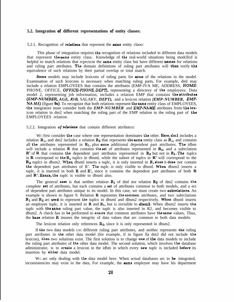
5.2. Integration of different representations of entity classes:
5.2.1. Recognition of relations that represent the same entity claoo:
This phase of integration requires the recognition of relations included in different data modelsthat represent the Bamc entity class. Knowledge of the real-world situations being modcllcd ishelpful to match relations that rcprcscnt the same entity class but have different names for relationsand ruling part attributes. The domain definitions of ruling part attributes will then verify theequivalence of such relations by their partial overlap or total match.
Some models may include lexicons of ruling parts for some of the relations in the model.Examination of such lexicons is necessary when matching ruling parts, For example, dml mayinclude a relation EMPLOYEES that contains the attributes (EMP-JVA ME, ADDRESS, HOME-PHONE, OFFICE, OFFICE-PIIOiVE, DEPT), representing a directory of the employees. Datamodel 2, representing job information, includes a relation EMP that contains the attribute8(EMP-WMBER, AGE, JOB, SALARY, DEPT), and a lexicon relation (EMP-NUMBER, EMP-lVA ME) (figure 9a). To recognize that both relations represent the game entity class of EMPLOYEES,the integrators must consider both the EMP-NUMBER and EM&NAME attributes from the lcx-icon relation in dm2 when matching the ruling part of the EMP relation to the ruling part of theEMPLOYEES relation.
5.2.2. Integration of relation8 that contain different attributco:
WC first consider the case where one representation dominates the other. Here, dml includes arelation RI, and dm2 includes a relation Rg that represents the same entity class as RI, and containsall the attributes represented in RI, plus Borne additional dependent part attributes. The idbmwill include a relation R that contains the set of attributes represented in RI, and a subrclationR’ of R that contains the dependent part attributes represented in R2 but not in RI. The tuplcsin R correspond to the R1 tuplcs in dbsml, while the subset of tuplcs in R’ will correspond to theR3 tuplcs in dbsm2. When dbsml inserts a tuplc, it is only inserted in R, since it does not containthe dependent part attributes of R’. The tuplc is only visible to dbsml. When dbsm2 inserts atuplc, it is inserted in both R and R’, since it contains the dependent part attributes of both Rand R’. Hence, the tuplc is visible to dbsml also.
The general ca6c is that neither relation R1 of dml nor relation R2 of dm2 contains thecomplete set of attributes, but each contains a set of attributes common to both models, and a ectof dependent part attributes unique to its model. In this case, we must create two subrelations. Anexample is shown in figure 9. Relation R represents the common attributes, and two subrclationsR1 and R2 arc used to represent the tuplcs in dbsml and dbsm2 respectively. When dbsml insertsan employee tuplc, it is inserted in R and RI, but is invisible to dbsm2. When dbsm2 inserts thetuplc with the same ruling part value, the tuplc is also inserted in R2, and becomes visible todbsm2. A check has to be performed to ensure that common attributes have the same values, Thus,the base relation R insures the integrity of data values that arc common to both data models.
The lexicon relation only references R2, since it is only represented in dbsm2.
If the two data models USC different ruling part attributes, and neither represents the rulingpart attributes in the other data model (for example, if in figure lla dm2 did not include thelexicon), then two solutions exist. The first solution is to change one of the data models to includethe ruling part attributes of the other data model. The second solution, which involves the databaseadministrator, is to create a lexicon in the idbm in which every new tuplc is included before itsinsertion by either data model.
WC arc only dealing with the data model here. When actual databases arc to be integrated,inconsistencies may exist in the data, For example, the game employee may have his department
28

relation R1 (EMPLOYEES)t EMP-NAME It ADDRESS-I HOME-PHONE 1 OFFICE 1 OFFICE-PHONE I DEP-NO 1
DMl (directory of employees)
relation R2 (EMP) (lexicon)[EMP-NO~~AGE~JOBISALIDEP-NO] [EMP-NoIIEMP-NAME/
DM2 (job information)(a)Lcxicon of a ruling part that must be considered
relation R subrelation R2 (subset in DBSMZ)[ EMP-NAME 11 DEP-NO 1 (<<< 1 EMP-NAME 11 AGE 1 JOB 1 SAL 1
2A subrclation RI (subset in DBSMl)
1 EMP-NAME II ADDRESS I HOME-PHONE 1 OFFICE 1 OFFICE-PHONE 1
(lexicon, visible to DBSM2 only)[EMP-NAME ]jEMP-NO1
(b)Intcgratcd database model
Figure 9, Integration of different sets of attributes (with lexicon)
listed as ‘foundry’ in one data model, and as ‘management’ in another. This problem is a postdesign issue, although WC note that the structural model would not allow this inconsistency if thedifferent submodcls insert their tuplcs representing the mrnc employee at different times.
WC also note that although many subrclations may exist for the same base relation in theintegrated database model, this is only at the model level. At the implementation level, the baserelation and all its subrelations may be placed in the same file, with a conditional field for eachsubrclation in each record to indicate whether the record is in the subrclation or not. It may alsobe worthwhile to change database submodcls by making them aware of a few additional attributesto simplify the database model.
5.2.3. Integration of relations that represent different sets of tuplcs:
WC know consider the cast where there arc differences in the selection of entities to be rcp-resented. For example, if one data model, dml, includes a relation RI, and dm2 includes a relationR2 that represents a 6Ub6ct of the tuplcs in RI. The idbm will then include a relation R and asubrelation R2 of R to represent the tuplcs in R2 of dbsm2, The subrelation R2 may be a restrictionsubrelation if the 6Ub6ct of tupl’cs in R2 is determined by attribute values in R, or a non-restrictionsubrelation if the eubsct of tuplcs in R.2 is determined externally, independent of the model.
For example, dml (for the payroll department) may represent all employees of a companyin an EMPLOYEES relation, while dm2 (for the sales department of the company) includesthe relation SALES FORCE, the cmployccs that work in the sales department. The idbm thenincludes a relation EMPLOYEES, and a subrelation SALES FORCE of EMPLOYEES. If theEMPLOYEES relation contains a DEPARTMENT attribute, the subrelation SALES FORCE isa restriction subrclation on the DEPARTMENT attribute, restricting the attribute to the valuesales. Jf EMPLOYEES does not contain a DEPARTMENT attribute, SALES FORCE would bea non-restriction subrclation. In either CBSC, after integration, dbsm2 is only allowed access totuplcs in the SALES FORCE subrclation, but could still access their attribute values from thebase relation EMPLOYEES, while dbsml would be allowed access to all employee tuplcs.
29

The general case is that the tuplce in the two relations partially overlap each other. Then dmlincldcs relation R1 and dm2 includes relation R2 that represent the same entity class, such thatthe tuplcs in the two relations obey the constraints RI n R2 fl 0, Rl-Rg # $, and R2 - R1 fl $.
The idbm then includes a relation R = R1 U RQ, and two subrelations of R, R1 and R2. Again,R1 or R2 could be either restriction or non-restriction subrclations, For example, rcfcring to auniversity database, dml (representing the computer science department of the university) includesa relation CSD PROFESSORS, and dm2 (representing information about permanent faculty) in-cludes a relation TENURED PROFESSORS. The idbm then includes a relation PROFESSORS,and two subrclations of PROFESSORS, CSD PROFESSORS and TENURED PROFESSORS.Each database submodcl is allowed access to his subset, and the base relation assures the integrityof common data represented in both models,
In the last example, it is possible that the relation in each data model contains attributescommon to both relations, and a set of it6 own attributes. Then, the base relation in the idbmwill contain the common attributes, and each subrclation will contain its own additional set ofattributes,
5.3. Integration of diff went representations of relationships:
In the following sections (5,3.1 - 5.3.4), WC assume that WC have two data models, dml anddm2, and that both data models represent two entity classes A and B, and a relationship betweenthem, R, and Rs will denote the relations that represent entity classes A and B. If the representationof the relationship between A and B involves an auxiliary relation (association, primary or nestrelation) WC will designate it Rob.
There arc five ways of representing a relationship between two entity classes in the structuralmodel (section 4.2). Thrcc of these representations arc not symmetric with respect to A and B(reference, nest, nest of references), and two arc symmetric (association, primary). If WC considerall possible combinations without looking at symmetries, the set of possible ~86~8 for combiningdifferent representations pairwisc is 2 X (5 + 4 + 3 + 2 + 1) = 30. WC remove 5 CBBCB wherethe representation is identical in both data models, and (5 -/- 4) cases because the association andprimary cases arc symmetric with rcspcct to & and Rb. Then 18 CBBCB remain to be considered.WC consider all possible combinations with the association representation first (4 cases) in section5.1.1. WC then consider the cases that remain with nest of references (8 cases, section 5.1.2), withreferences (4 casts, section 5.1.3), and with nest (2~6, section 5.1.4).
5.3.1, Integration with an association:
In thia section, WC consider integration of an association with other representations of arelationship. In those cases, dml represents the relationship A:B as an association relation, anddm2 will USC a different representation, The association may represent a relationship of cardinalityM:N, Our assumption (section 4.2) that both original data models accurately represent the samesituation implies that the cardinality of both representations is the same. Hence, the cardinalityof the relationship is restricted to the rcprcscntion in dm2.
the iIn order to demonstrate how two different data models may be integrated, WC will
ntcgration of an association with the nest of references (figure lOa).present
In this case, the only difference is that dml can freely delete tuplcs from Rb, while in dm2deletion is restricted by referencing tuplcs from nab. Hence, WC create two subrclations, Rbl andRable Those subrclations represent the tuplcs in Rb (and Rob) of dbsml. Tuplcs in Rb and &bin the idbm may include some tuplcs deleted from dbsml, but not deleted from Rb and Rob inthe idbm due to the deletion constraint of the rcfcrcncc in dbsm2, These tuples arc not visible todbsml.
30

dml dm2association nest of references
idbm
IRo
Figure 10a. Integration of association and nest of references
The database submodcls now obey the following rules. Insertion and deletion in R. from eitherdbsml or dbsm2 is unrestricted, as is deletion of Rab tuplcs, and unreferenced Rb tuplcs. If dbsmldeletes a referenced Rb tuplc (dbsm2 may not perform such a deletion), it is only deleted fromRbl (and the owned tuplcs arc deleted from RobI). These rules accurately reflect the constraintsimposed by the views represented in the original data models.
For brevity, WC will USC the following format for each integration case. WC first list thedifferences between the two data models, then list the additional integrity constraints that have toexist in the mapping from the database submodcls to the integrated database model. When listingthese additional constraints, ( ‘relation name” ) will mean: do the insertion or deletion specifiedon %clation” if allowed by the integrity constraints of the idbm.
WC will now present the demonstration case again in brief notation.
(a) ASSOCIATION AND NEST OF REFERENCES(figure loa):
Differences:
Dml may freely delete tuplcs from Rb, while in dm2, deletion of % tuplcs is restricted.
Additional constraints:dbsml:insert: (1) & - %Jbl, (2) Rob- (RobtRoddelete: (1) Rb - (Rb),Rbl
dbsm2:hcrt: (1) & - %,R~l, (2) Rob - (%b,(%bl))
The relation name to the left of the y-” refers to the database submodel, while those to theright refer to the database model. WC only consider cases which need additional control from theconstraints. Insert in & of dbsml hence means insert in R. of the idbm, since it is not listed. Indbsml, insert in Rb requires insertion of the tuplc in both Rb and Rbl of the idbm. Insert in Rabrequires insertion in (Rob,Robl) in the idbm, the ( ) brackets meaning if the integrity check of theidbm will allow it, here if both owner tuplcs exist. In dbsm2, insert in Rab requires insertion in(Robr(Robl)), which means: insert the tuplc in Rab if the integrity check of the ibdm holds (hereboth the owner tuplc in R, and the referenced tuplc in Rb exist), than insert the same tuplc inRob1 (if the other owner tuplc exists in Rb&
Following each integration case, WC will give an example with attributes to illustrate theintegration process. Example 1 illustrates the integration of association and nest of references.
31
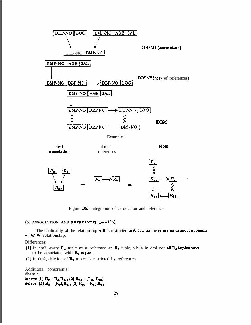
\ /
1 DEP-NO 1 EMP-NO 1DBSMl (association)
IEMP-NOI1 AGEISAL]
4IEMP-NO IDEP-NO/j---->[DEP-NO IILOC]
DBSMS (nest of references)
IEMP-NOliAGElSALj
[EMP-NO~DEP-NO+~DEP-N~IIL~C]
fiA
[EMP-NOIDEP-NO[
dml d m 2association references
Example 1
IDBM
idbm
+ 4Figure lob. Integration of association and reference
(b) ASSOCIATION AND REFERENCE(figurc lob):
The cardinality of the relationship A:B is restricted to N:l, since the reference cannot representan MN relationship,
Differences:(1) In dm2, every & tuplc must rcfcrcncc an Rb tuplc, while in dml not all b tuplco have
to be associated with Rb tupk
(2) In dm2, deletion of R+ tuplcs is restricted by references.
Additional constraints:dbsml:insert: (1) Rb - Rb,Rbl, (2) Rob - (%a%b)
dclcte: (1) Rb - (Rb)rRbl, (2) Rob - %2&b
32

DBSMl (association)
( E M P- NO II A G E I S A L 1 D E P- N O I->/ D E P- N O 11 LOC 1DBSM2 (reference)
1 EMP-NO It AGE 1 SAL 1
[EMP-NO 1 DEP-No 1 B3BM
&J>
Example 2
dml dm2association nest
idbm
Figure 10~. Integration of association and nest
dbsm2:insert: (1) & - (&,Ra2,(&b)), (2) Rb - Rb,Rbl
The requirement that every R, tuplc must reference an II.6 tuplc in dm2 leads to the creationof the subrelation Ro2, while the unrestricted deletion of Rb tuplcs in dml leads to the creationof Rbl (example 2).
(c) ASSOCIATION AND NEST(figurc 10~):
The cardinality of the relationship A:B is restricted to l:N, since the ownership connectioncBn only represent 1:N relationships.
Diff crcnccs:(1) In dm2, existence of a tuple in Rb requires the existence of the owner tuplc in &, while
in dml, Rb tuplcs can exist independently.(2) In dm2, deletion of a tuplc from R, requires the deletion of the owned tupler in &,, while
dml does not require these deletions.
Additional constraints:dbsm2:insert: Rb - (Rb,Rbl)
33

1 DEP.NO II LOC ] LEMP-N0 II AGE I SAL 1
\ /1 DEP-NO 1 EMP-NO u
(U)
DBSMl (arsociation)
1 DEP-NO 11 LOC j
I1 DEP-NO 1 EMP-NO 11 AGE 1 SAL 1 DBSM2 (nest with unique identification)
w>
[ DEP.NO II LOC 1 [EW-NO 11 AGE 1 SAL ]
1 DEP-NO 1 EMP-NO u
UJ)
Example 3
dml dm2association primary
IRob
IDBM
idbm
Figure 10d. Integration of association ana primary
The Rb tuplcs of dbsm2 arc only those in Rb2 in the idbm, since they require the existenceof the owner tuplc. In the idbm, Rob will also represent the subset of Rb tuplcs in Rb3.
Here, WC must consider two examples, since the nest relation may represent different tuplcidentification attributes than the association. First, WC consider the case where the identificationis the same. In example 3, EMP-NO identifies the employee in both dbsml and dbsm2. Sincethe cardinality of DEPARTMENT:EMPLOYEE is l:N, the EMP-NO attribute must have uniquevalues in tuplcs of the relations marked (U). Note that this does not violate Boyce-Codd normalform. In this cam, the integration is straightforward.
In example 4, the identifying information is different. Dbsm2 uses the two attributes (EMP-NO, CHILD-NAME) as ruling part, while dbsml uses only CHILD-ID. CHILD-ID uniquelyidentifies every child tuplc, but CHILD-NAME does not. Here, if dbsm2 does not represent theattribute CHILD-ID, he has to be made aware of it to maintain the correct mapping betweenCHILD-ID and CHILD-NAME on ins&ion of child tuplcs.
(d) ASSOCIATION AND PRIMARY(figurc 10d):
The cardinality of the relationship A:B is M:N.
Differences:In dm2, deletion of & and Rb is restricted by references
34
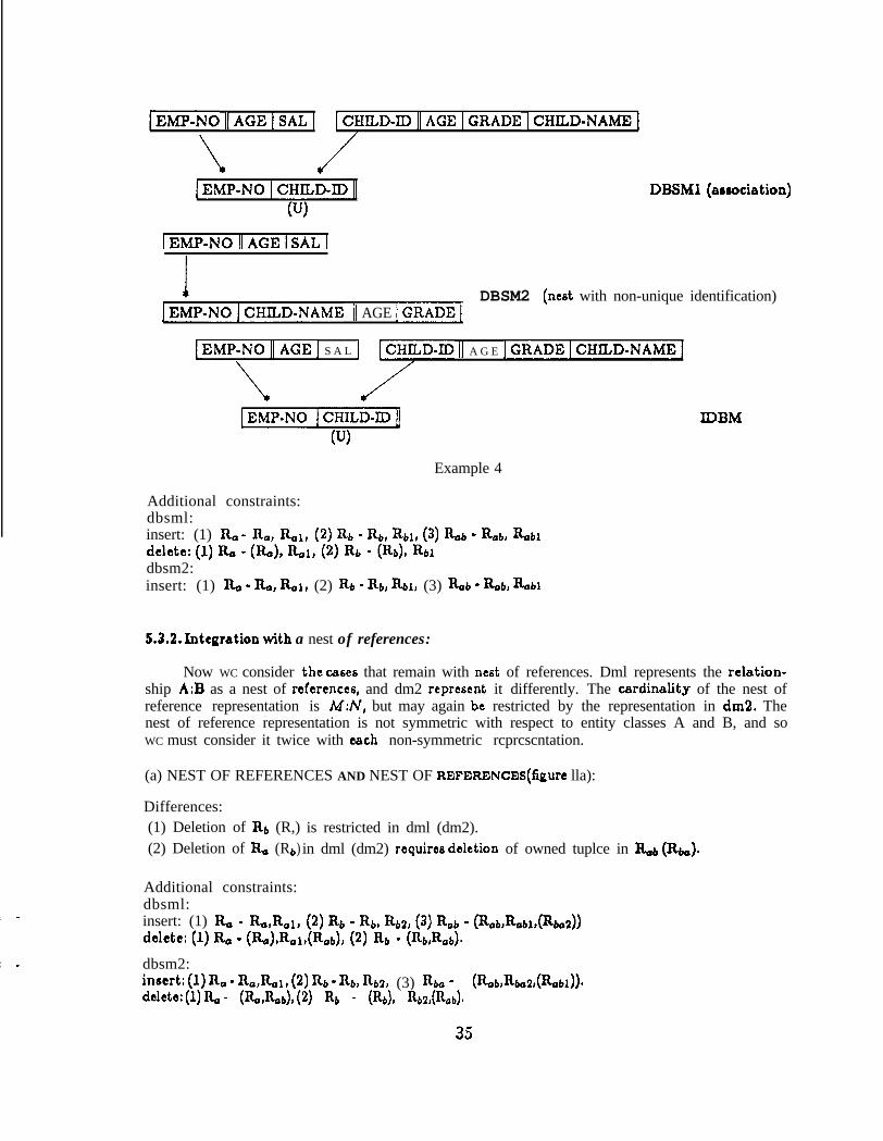
[EMP-NO 11 AGE 1 SAL ] ICHILD-IDIIAGEIGRADE ICHILD-NAME1
\
IEMP-NOICHILD-ID[
(U)
DBSMl (aeaociation)
IEMP-NOIIAGEI sALI
IIEMP-NOjCHXLD-NAME 11 AGE /GRADE1
DBSM2 (nest with non-unique identification)
[EMP-NOI~AGEI S A L ] LCHILD-D II A G E IGRADEICHILD-NAMEI
\
[EMP-N0 I~HILD-~JI] XDBM
P>
Example 4
Additional constraints:dbsml:insert: (1) R, - no, Rol, (2) &a - Rtn Rbl, (3) %b - Rob, Rob1ddctc: (1) Ro - @a), %A, (2) Rb - (%), Rbldbsm2:insert: (1) & - &, &I, (2) RI, - Rb, Rbl, (3) kb - Rob, Robi
5.3.2. Integration with a nest of references:
Now WC consider the ca~tx that remain with nest of references. Dml represents the rclation-ship A:B as a nest of rcfcrcnccs, and dm2 reprcscnt it differently. The cardinality of the nest ofreference representation is M:N, but may again be restricted by the representation in dm2. Thenest of reference representation is not symmetric with respect to entity classes A and B, and soWC must consider it twice with each non-symmetric rcprcscntation.
(a) NEST OF REFERENCES AND NEST OF REFERENCES(figurc lla):
Differences:(1) Deletion of Rb (R,) is restricted in dml (dm2).(2) Deletion of Rg (Rb in dml (dm2) requires deletion of owned tuplce in &b (k).)
Additional constraints:dbsml:insert: (1) R, - Ro,Rol, (2) Rb - b Rb2, (3) Rob - (&brRoblt(Rbo2))dclctc: (1) Ro - (%),Rol,(Rob), (2) & - (%Rob)~
dbsm2:hwrt: (1) &a - RotRol, (2) Rb - Rbr %2, (3) ho - (Rodbo2,(Rou))~delctc: (1) Ro - (%,Rob)r (2) % - (h), Rb2,(%d
35

dmlnest of references
dm2nest of reference6
idbm
Figure 11s. Integration of nest of references and nest of references
[ EMP-NO [I AGE 1 SAL ]
I1 EMP-NO 1 DEP-NO ~------>I DEP-NO 11 LOC ]
DBSMl (nest of rcfercnccr)
1 DEP-NO 11 LOC ]
IIDEP-NO~EMP-NO +>[EMP-NOIIAGEI SAL]
DBSM2 (nest of references)
/EMP-NO 1 DEP-NO 1)) [ EMP-NO ] DEP-NO 1 << 1 EMP-NO I DEP-NO [
Example 5
When dbsml tries to delete an R, tuplc in the idbm that is referenced from Rb3, it is onlydeleted from R,l. If the tuplc is not referenced from Rbo2, the tuplcs in &b that correspond tothose deleted from R&l (due ti the deletion of R,) should also be deleted, since they no longerexist in either RobI or &b2. Rob exists to ensure that the tuplcs associating tuplce from & withtuplc from Rb arc consistent.
Example 5 illustrates this case.
(b) NEST OF REFERENCES AND REFERENCE(figurc lib, 11~):
Both nest of references and reference arc non-symmetric, 60 WC murt examine two CBBCB.
Case 1 (figure lib):
The cardinality of the relationship A:B is restricted to N:l, since the reference cannot rcprcecntan N:M relationship.
36

dmlnest of references
Figure 11 b. Integration of nest of references and reference (Case 1)
dm2 idbmreference
+
[Rob R 02( R )f ed
1 EMP-NO 11 AGE 1 SAL )
I[ EMP-NO I DEP.NO +)[DEP-NO II LOC 1 DBSMl (nest of references)
UJ)
DBSM21 EMP-NO 11 AGE 1 SAL 1 DEP-NO /--->I DEP-NO 11 LOC]
(reference)
[ EMP-N0 11 AGE I SAL ]A
1( i81 EMP-NO 1 DEP-NO D-->l DEP-NO 11 LOC 1 IDBM
w
Example 6
dml dm2nest of references reference
idbm
ElRo
I
+
Figure llc, Integration of nest of references and reference (Case 2)
Differences:
A tuplc in & in dm2 must be associated with an Rb tuplc.
Additional constraints:dbsm2:insert: & - (&,%Q)
~6t3 2 (figure llc):
Again, the cardinality of the relationship A:B is restricted to l:N.
37

IDEP-NOIILOC]
I[DEP.NO IEMP-NO I-->[ ~h4p-N0 11 AGE 1 SAL 1 DBSMI (nest 0f references)
u4
[ EMP-NO 11 AGE [ SAL 1 DEP-NO +>I DEP-NO 11 LOC 1DBSM2 (reference)
11 AGE 1 SAL 1
/[ DEP-NO 1 EMP-NO 0 )) 1 DEP-NO 1 EMP-NO I]
(U> (U)
Example 7
dml dm2nest of references nest
t I I1
W
<< [EMP-N~ IIDEP-No1 xrx3M
idbm
Figure lid, Integration of nest of rcfcrcnces and nest (Casa 1)
Differences:(1) Deletion of Rb (h) tuplcs is restricted in dml (dm2).(2) Every Rb tuple in dm2 must be related to an & tuple.
Additional constraints:dbsml:ins&: (1) &J - &&al, (2) Rab - (R-obl, %btRbZ) l
delete: (1) &a - (Ro)r~t&.a~), (2) &t - (&ubJ, (3) Rob - &au, (%t$
dbsm2:insert: (1) R, - RJb, (2) Rb - (% &db,Robl)~dclctc: (1) Ra - (RJb,), (2) Rb - (Rb, %b),Rb
Example 7 illustrates this case.
(c) NEST OF REFERENCES AND NEST(figurc lid, 11~):
Again, both nest of rcfcrcnccs and nest arc non-symmetric, M) WC must examine two CMCS.
Case 1 (figure lid):
The cardinality of the relationship A:B is restricted to l:N, since the reference cannot rcprcecntan N:M relationship.
38

I DEP-NO 11 LOC 1
[PEP-NO 1 EMP-NO /j
w
>[ EMP-NO II AGE 1 SAL ] DBSMl (neat of rcfcrcnccs)
1 DEP-NO 11 LOC 1
[ DEP.NO ] EMP-N0 11 AGE 1 SAL 1 msM2 (nest)
&J)
~~D~~~-No//Loc]
IEMP-NO ilDEP-NO]>> IEMP-NOIDEP-NOi IDBMUJ)
Example 8
Differences:(1) Rb tuplcs may exist independently in dml.
(2) Deletion of R+ tuplcs is restricted in dml.
Additional constraints:dbsml:insert:. Rob - (Rlrb,R&
dbsm2:inscrt: Rb - (Rb,Rob,Rbg).delete: Rb - (Rb),Rb2.
WC again consider two examples, because of the different ways the nest relation may rcprc-sent the tuplc identifying information. In example 8, WC consider the c8sc where the identifyinginformation is the 6amc.
In example 9, WC now consider the case where the identifying information is different. Here,WC must slightly change dm2 by introducing an additional attribute.
tiSC 2 (figure llc):
The ardinality of the relationship A:B is restricted to N:l.
Diff crcnccs:
(1) In dml, R, tuples can exist independently, while in dm2 an owner tuplc Rb tuplc mustexist.
(2) In dml, deletion of Rb tuplcs is restricted by rcfcrcncc6, while in dml, deletion of an R+, ’tuplc requires deletion of related & tuplcs.
39

[ DEP-NO 11 LOC ]
1 DEP-NO 1 EMP-NO j->[ EMP-NO 11 AGE 1 SAL ] DBSMl (nest of references)w
!IDEP-NOIEMP-IDIjAGEISAL] -1
DBSM2 (nest)
IEMP-NOIIAGE] SAL]
[EMP-NOIIDEP-NO IEMP-ID] >) [EMP-NO IDEP-NOI IDBM
Example 9
dml dm2nest of references nest
idbm
Figure 11~. Integration of nest of rcfcrcnccs and nest (Case 2)
Additional constraints:dbsml:insert: (1) Rb - %db2, (2) Rob - (%u (&32))4
dbsm2:ins&: (1) R, - (Ro,Ra2,Ra~), (2) Rb - &Jbdelete Rb - (Rb),Rb2.
WC will only consider one example for this case, example 10, with different identification.
(d) NEST OF REFERENCES AND PRIMARY(figurc llf):
The ardinality of the relationship A:B is M:N.
Differences:In dm2, deletion of R, is restricted by rcfcrcnccs
40

1 EMP-NO 11 AGE 1 SAL 1
1 EMP-NO I DEP.NO 1)--->I DEP-NO II LOC 1 DBSMl (neat of rcfcrcncce)w
1 DEP-NO 11 LOC 1
!1 DEP.NO 1 EMP-ID 11 A G E 1 SAL ] p]
DBSM2 (nest)
IEMP-NOjjAGE]SAL]
[EMP-N~]DEP-No&-->[DEP-~0 IILocj
k w> AA A IDBM
IEMP-NOIIDEP-NOjEMP-ID]~~[
Example 10
dmlnest of references
L-J&I +
dm2primary
idbm
Figure llf. Integration of n&of rcfcrcnccs and primary
Additional constraints:dbsml:insert: (1) R, - Rx, %I, (2) nab - nab, nab1delete: (1) & - (R,), Raldbsm2:insert: (1) R, - Ra, &al, (2) Rob - Rab, Rob1
5.3.3. Integration with a reference:
Dml represents the relationship A:B as a rcfcrcncc connection from IL to &, and dm2represents it using a different structure. The cardinality of the relationship A:B is N:l, possiblyrestricted by the dm2 representation.
(a) REFERENCE AND REFERENCE(figurc 128):
The cardinality of A:B is restricted to l:l, since in dml it is JV:l, and in dm2 it is 1:/V. Itwould be unusual to encounter thcsc two rcprcscntations of the game a 1:l relationship. Howcvcr,it can be integrated,
41

dml dm2reference rcfcrcncc
+
pt+--~~Rb]pq--+pq
idbm
Figure 12a. Integration of rcfcrcncc and reference
IDEP-NO/ LOC /M A N A G E R-N O /--->[MANAGER-NO]/AGE[ SAL] DBSMl (reference)
PI
[ M A N A G E R- NO 11 AGE /SAL [DEP.NO~--)[DEP-NO (BLOC] DBSMZ(rcfcrcncc)W)
1 DEP-NO 11 LOC 1 MANAGER-NO 11 AGE 1 SAL ]
Artr
A1 DEP-NO 11 MANAGER-NO AGER-NO 11 DEP-NO 1 IDBM
(U) UJ) (U) UJ)
Example 11
dml dm2reference nest
+ c lRb
pii-/-+~l I
4
idbm
El&I pi++RbljFigure 12b. Integration rcfcrcncc and nest (Case 1)
Differences:
(1) In dml (dm2), every R, (Rb) tuplc must rcfcrcnce an I& (R,) tuple.
(2) Deletion of Rb (R,) tuplcs is restricted in dml (dm2).
Additional constraints:dbsml:insert: R, - (Ra~Ral~Rabrhtl)*delete: R, - (&),~o&Lt$
dbem2:insert: Rb - (Rb,Rb2,Rob,R&delete: Rb - (Rb),Rb2,(Rob).
(b) REFERENCE AND NEST(figure 12b,12c):
case 1 (figure 12b):
The cardinality of the relationship A:B is NJ.
42

1 EMP-NO 11 AGE 1 SAL ] DEP-NO /--->[ DEP-NO 11 LOC ]DBSMl (rcfcrcncc)
[ DEP-~0 II LOC ]
1 DEP-NO 1 EMP-NO 11 AGE 1 SAL ] DBSM2 (nest)
RJ>
[ EMP-NO 11 AGE ] SAL ] DEP-NO j----->[ DEP-NO 11 LOC ]
[EMP-NO 1 DEP-NO jj*
(U>
{ DEP-NO jj IDBM
Example 12
dmlreference
dm2nest
idbm
Figure 12~. Integration of reference and nest (Case 2)
Differences:(1) In dbsml, deletion of Rb tuplcs is restricted by referencing.(2) In dbsm2, deletion of an Rb tuple requires deletion of related tuplco in It,,.
Additional constraints:d bsml:insert: (1) & - (L(h)), Rb - Rb, Qs
dbsm2:insert: Ra - (Ra,Ro2), Rta - Rta, Rb2edelete: Rb - (Rb),Rb2.
Example 12 illustrates this case by a 1:N relationship between DEPARTMENTS:EMPLOYEES.
cJ36t¶ 2 (figure 12c):
The cardinality of the relationship h:B is restricted to l:l, since in dml it is N:l, and indm2 it is l:N,
Differences:(1) Every R. tuplc in dml must reference an Rb tuplc, while in dm2 every & tuplc must be
owned by an R, tuple.(2) Deletion of Rb tuples is restricted in dml.(3) Deletion of an R. tuplc in dm2 requires deletion of owned & tuples.
43

1 DEP-NO 11 LOC 1 MANAGER-NO}->/ MANAGER-NO 11 AGE 1 SAL 1 DBSMl (reference)
&J>
1 DEP-NO 11 LOC ]
I[ DEP-NO I MANAGER-NO 11 AGE ] SAL ] msM2 (nc6t)
uJ> (U)
1 DEP--1 MANAGER-NO 11 AGE 1 SAL]AA
[ DEP-NO 11 MANAGER-NO I-+-[ MANAGER-NO I] IDBM
(U)
Example 13
dml dm2reference primary
idbm
+
Figure 12d. Integration of reference and primary
Additional constraints:dbsml:inmrt: Ro - (&JL1,Rb2)
dbsm2:insert: Rb - (Rb,R,,l,Rbs)delete: Rb - (Rb),Rbl
Example 13 illustrates this case,
(c) REFERENCE AND PRIMARY(figurc 12d):
The cardinality of the relationship A:B is N:l,
Differences:In dm2, deletion of & is restricted by references
Additional constraints:dbsml:insert: Rb - IQ,, (Rbldelete: (1) Rb - (Rbl, (Rb))dbsm2:insert: (1) Rb - Rb, Rbf, (2) Rob - Rob, R,l
44

dml dm2 idbmnest nest
+
Figure 13a. Integration of nest and nest
[ DEP-N0 II Lot ]
1 Dip-NO I MANAGER-NO II AGE 1 SAL 1 DBSMl (reference)
UJ) w
1 MANAGER-NO 11 AGE ] SAL j
[MANAGER-NO ]DEP-NO II LOC 1 DBSM2 (nest)
&J> PI
[ DEP-NO 11 MANAGER-NO ] IDBM
(U> WI
Example 14
5.3.4. Integration with a neft:
(a) NEST AND NEST(figure 138):
The cardinality of A:B is restricted to 1:l.
Diff crenccs:(1) In dml (dm2), every Rb (Ri) tuplc must be owned by an I&, (Rb) tuplc.
(2) Deletion of an R, (Rb) tuplc in dml (dm2) requires deletion of the owned &, (I&) tuplc.
Additional constraints:dbsml:insert: R+ - (&&I)
dbsm2:insert: & - (Re,&2)
Example 14 illustrates this UUX.
45
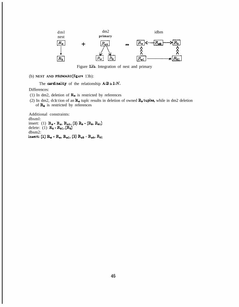
dml dm2nest primary
idbm
IIRb
+
Figure 13b. Integration of nest and primary
(b) NEST AND PRIMARY(figurc 13b):
The cerdinality of the relationship A:B is 1:N.
Differences:(1) In dm2, deletion of & is restricted by references(2) In dm2, d 1 tc c ion of an R, tuplc results in deletion of owned Rb tuples, while in dm2 deletion
of Rb is restricted by references
Additional constraints:dbsml:insert: (1) R, - R,, %I, (2) Rb - (R,, %I)delete: (1) R6 - Rbl, (Rb)dbsm2:insert: (1) Ra - Ra, &I, (2) R,b - Rob, Ru
46

dataIn this section,models.
6, RELATIONSHIP TO OTHER MODELS
we examine some of the similarities batwean the structural model and other
6.1. The relational model:
In relational model theory, the concepts of functional [Codd72] and multivalued Fagindependency among attributes arc important for normalization of relations and data model design.A functional dependency between two attributes Al and As, denoted by Al - AQ, means that foreach value of DOM(Al), a unique corresponding value of DOM(A2) can be determined. Functionaldependency between two sets of attributes is defined correspondingly. Attributes of a relation Rin Boyce-Codd normal form obey the constraint: if any attribute A in R is functionally dependenton a set of attributes X in R, and A is not in the set X, then all attributes in R arc functionallydependent on X.
All relations in the structural model arc in Boyce-Codd normal form, and hence obey the aboveconstraint. A functional dependency will also exist between each attribute in a referenced relation,and the ruling part of the referencing relation. Hence, a reference connection from a relation Rto another relation R’[Al, . . . A;] defines i functional dependencies K(R) g Aj; j = 1,. . .i. Thisis so because a functional dependency K(R) 9 Xr will exist in relation R, where X, is the setof referencing attributes in R. WC will also have the functional dependencies X, = K(R’) andK(R’) m Aj;j - 1 , , . .i, From the transitivity rule for functional dependencies, it follows thatK(R) - A j; j - 1,. . .i.
Since the structural model is constructed from relations, a relational query system based onthe relational algebra or the relational calculus cBn be used on the structural model. However,additional capabilities exist in the structural representation to simplify expression of queries bymaking u6e of represented connections. For example, consider the structural schema in figure8a. A query such as ‘FIND THE WORK LOCATION OF EMPLOYEE NUMBER 5” does nothave to be expressed a6 a join between two relations, since the reference connection specifics thedepartment tuplc that corresponds to the tuple representing employee number 5.
In the relational model, OAC has to specify integrity constraints to maintain tuples in differentrelations in a consistent state. IA the structural models, such constraints may bc specified implicitlyvia connections.
6.2. The hierarchical model:
A hierarchical model can. be expressed using relations as record types and ownership con-nections as hierarchical arcs. Hence, if a structural model is restricted such that only ownershipconnections are used, and such that all relations arc connected together in a tree structure, ahierarchical definition tree would result. The difference in representation is the redundancy createdby repetition of the ruling part attribute of the owner relations in the owned relations. However,such redundancy need not be implemented in a hierarchical implementation.
6.3. The network model:
The link set concept of the network model CBA be represented in the structural model. Anautomatic set can be defined using an ownership connection. Again, the only difference is theredundant representation of the ruling part attributes from the owner relation in the owned relation.
47

However, the existence of the connecting attributes implicitly specifies the set occuranca whena new member tuplc is inserted in the data model without requiring an additional procedure tospecify the correct owner.
A manual set can be represented by a 1:N association between two relations, as in the cx-ample of figure 8d. Here, the DEPARTMENTS relation corresponds to the owner type, and theEMPLOYEES relation to the member type. Employee tuplcs can exist without belonging to anydepartment tuple, and the set of members of each department owner tuplc is specified via theassociation.
The implementation oriented features of the hierarchical and network models arc implcmcn-tation dependent, and hence arc best left to the implementation phase. WC note that the structuralmodel may represent structures that are not part of any of the three other models, as shown insection 4.2.
48

7, THE DATABASE DESIGN PROCESS
This section eummarizcs the process of designing the database with the aid of the structuralmodel, and provides a brief discussion of wn6idCratiOn6 for model implementation. The approach,which WC only outline here, provides much of the motivation for concepts presented in the structuralmodel. A detailed description and analysis of the remaining steps of the database design processwill bc the eubjcct of a later report.
An overview of the entire dc6ign process for an integrated database system is given in figure14, WC define three group6 of people that partake in the design process: the potential u6cr6, theintegrators, and the implementors. These group6 will interact during the database design process.The vertical axis in figure 14 defines the activities of each group relative to a time frame.
A potential u6cr is a group of pcoplc or application program6 that expect to u6c the databasesystem. Many such potential u6cr6 will exist since WC arc designing a large, integrated database.Each potential u6cr must analyst hi6 requirements, and dcfinc a data model with expected loadestimates. Since a database typically 6crvc6 many diverse but potentially related interests, manysuch data models can be established.
In section 4.1, WC showed how the structural model guide6 the design of data models. Additionalinformation is solicited from the potential u6cr about hi6 expected u6c of hi6 data model. Thisinformation is not part of the data model, but is attached to the relations and connections ofhi6 data model. This includes additional integrity constraints, and expected retrieval and updatecharacteristics for the data model. Load estimates will be classified into several update and retrievalcomponents on the relations and connection6 of the data model.
The database integrators then undertake to combine these data models into an integrateddatabase model. In the process of combining the data models, conflict6 may arise which have tobe resolved by changing 6omc of the data models. There may be data models which turn out tobe unrelated, or weakly related, to the core of the integrated database model 60 that they arc notincluded. The result of the data model integration is to define preliminary database submodels forthe u6cr groups. This process will need consultation with the u6cr6 if their data model ha6 to bechanged.
The integrators then combine the load estimates from the individual u6cr data model6 andproduce load cstimatcs for the database model. When the transformation from data models todatabase model is simple, the load estimates can simply be added together. In complex situations,load data will have to be transformed to correspond to the transformation from the data modelsto the database model.
The implcmctors then u6c the cummulative load estimates on relations and connections todesign the file structures and accc66 methods. They take into account the expected update andretrieval load6 for the databasc.modcl. Connections that arc expected to be used frequently shouldbe explicitly rcprcscntcd in the implementation. A methodology for designing the file structuresand access methods based on the expected update and retrieval characteristics of relations andconnections will be described in a later report.
When usage patterns change, it is reasonable to change implemented file structures and accc66methods without affecting the structural database model. Only the performance of retrieval andupdates along model relations and connections whose implementation is changed will be affected.Provisions should be made in the implementation for such a restructuring.
Provisions must also be made for changing u6cr data models, or for deletion of existingsubmodels and addition of new data models. This may cau6c a change in the database model.Structural model changes which only affect rarely used connections will be easier to accomodatcthan changes which affect very critical and tightly bound connections.
49

Ti
mC
Y
in a
USERS XNTEGRATORS
Requirements analysie
Data models construction
Load estimates on datamodels
Data models integrationinto database model
Database submodels dc-fined on database model
Load integration ontodatabase model
Alternative performance Filc design decisionestimates
IMPLEMENTORS
Alternative file selectionsanalysis
Performance prediction
Figure 14. The integrated database design process
WC will address the issue of database design and implementation using the structural modelseparate report. WC will give a quantitative approach to database design, and discues possible
implementation choices for the structural model constructs.
50

8. Conclusions:
The model WC have presented provides a bridge between the simplicity of the relational modeland the explicitness of the network model. On the one hand, all structures in the model arc relationsin Boyce-Codd normal form 60 that the uniformity of the relational model is maintained. Querytcchniqucs devised for relational models can be easily incorporated into the structural model. Onthe other hand, important structural information about the real-world situation is incorporatedin the data model, and provides important knowledge both for potential u6cr6 and for databasesystem implementors.
W C then showed how the different rcprcscntations in two data models can be integrated,leading to the construction of an integrated database model which correctly supports the differentdata models of the u6cr6. The integrated database model then supports the u6cr submodels.
Our point of view of the implementation process is that connections between relations haveto be carefully considered. Binding of important connections will cau6c reasonable 1cvcls of pcr-formancc to be achieved, At the same time, unbound connections remain recognized, and may beemployed when restructuring due to changing demands becomes necessary. The decision of whichconnections to bind is best supported by inclusion of connections which arc candidates for bindingin the database model.
51

Ref cmmcetz
[Abrial74] Abrial, J,R., ‘Data Semantics”, in J.W.Klimbia and K.L.Koffcman (cds.), “DataBase Management” (Proc. IFIP Conf. on Data Base Management), North-Holland, 1974,pp.l-60
[Chang78] Chang, S.-K, and W.-H.Cheng, “Database Skeleton and its Application to LogicalDatabase Synthesis”, IEEE Trans. on Software Engineering, VolSE-4, No.1, January1978, pp.18-30
[ChcnllB] Chcn, P.P.S., ‘The Entity-Relationship Model - Towards a Unified View of Data”,ACM Trans. on Database Systems, Vol.1, No.1, March 1976, pp.9-36
[Codd’lO] Codd, E.F., “A Relational Model for Large Shared Data Banks”, Comm. ACM,Vo1.13, No.& June 1970, pp.377-387
[Codd72] Codd, E.F., “Further Normalization of the Data Base Relational Model”, in R.Rustin(cd.), “Data Base Systcm6”, Courant Comp. Sci. Symp., Volume 6, Prentice-Hall, 1972,pp.33-64
[CODASYL74] CODASYL Data Description Language, Journal of Development (June 1973),National Bureau of Standards Handbook 113, Gov. Printing Office, Wash.D.C.,Jan. 1974,155 pp.
pcBlasi677] DcBlasis, J.P. and T&Johnson, “Data Base Administration - Classical Pattern,Some Experiences and Trends”, Proc. NCC, 1977, AFXPS Vol.46, pp.l-7
[Eswaran75] Eswaran, K.P. a n d D.D.Chambcrlin, ‘Functional Specifications of a Subsystemfor Database Integrity”, in D.S.Kcrr (cd.), ‘Very Large Data BascB", (Proc. Intl. Conf.on VLDB), ACM, 1975
Fagin Fagin, Ronald, ‘Multivalued Dependencies and a New Normal Form for RelationalDatabases”, ACM Trans. on Database Systems, Vol.2, No.3, Sept. 1977, pp.262-278
Fry761 Fry, J.P. and E.H.Siblcy, “Evolutionof Data-Base Management Sy6tcm6”, ACM Comp.Surveys, Vo1.8, No.1, March 1976, pp.7042
[Hammer781 Hammer, M. and D.McLcod, ‘The Semantic Data Model: A Modclling Mechanismfor Data Base Applications”, in E,Lowenthal and N.B.Dalc (cd&), ACM SIGMOD Intl.Conf. on Management of Data, Austin, Tcxa6, 1978, pp.26-36
[Kent771 Kent, W., “New Criteria for the Conceptual Model”, in P.C.Lockcmann and E.J.Ncuhold(cde.), “Systems for Large Data Bases” (Proc. 2nd Intl. Conf. on VLDB), North-Holland,1977, pp.l-12
[Manachcr75] Manachcr, S., “On the Feasibility of Implementing a Large Relational Data Basewith Optimal Performance on a Mini-Computer”, in DS.Kcrr (cd.), ‘Very Large DataBases” (Proc. Intl. Conf. on VLDB), ACM, 1975, pp.175-201
[Mylopoulos75] Mylopoulos, J. And N.Roussopoulos, ‘Using Semantic Networks for Data BaseManagement”, in DS.Kcrr (cd.), “Very Large Data Ba6C6”, (Proc. Intl. Conf, on VLDB),ACM, 1975, pp.
[Navethe Navathc, S.B. and MSchkolnick, “View Representation in Logical DatabaseDesign”, in E.Lowcnthal and N.B.Dalc (cd&), ACM SIGMOD Intl. Conf. on Managementof Data, Austin, Texas, 1978, pp,144-156
[Schmid75] Schmid, H.A. and J.R.Swcnson, ‘On the semantics of the relational model”, inW,F.King (cd.), ACM SIGMOD Intl. Conf. on Management of Data, San Jo~c, California,1975, pp.211-223
[Si blcy76j Sibley, E.H., ‘The Devclopmcnt of Database Technology”, ACM Computing Surveys,Vo1.8, No,l, March 1976, pp.l-7
52

[Smith771 Smith, J.M. and D.C.P.Smith, ‘Database Abstractions: Aggregation and Generalization”,ACM Trans. on Database Systems, Vol.2, No.2, June 1977, pp.105-133
[Stccl75] Steel, T,B.,Jr., ‘ANSI/X3/SPARC Study Group on Data Base Management SystemsInterim Report”, FDT (pub. ACM SIGMOD), Vo1.7, No.2, 1975
[Stoncbrakcr74] Stoncbrakcr, M., “High level integrity assurance in relational data base managc-mCnt 6)‘6tCIll6”, Electronic Research Lab. report ERL-M473, University of California,Berkeley, California, May 1974
[Taylor761 Taylor, R.W. and R.L.Frank, “CODASYL Data-Base Management Sy&cm6”, ACMComputing Surveys, Vo1.8, No.1, March 1976, pp.670104
[Teichritzis76] T ’ h ‘t61c rl zig, D,C. and FKLochovsky, ‘Hierarchical Data-Base Management”,ACM Comp. Surveys, Vo1.8, No.1, March 1976, pp.105-124
[Tsichritzis’l’l] Tsichritzis, D. and FLochovsky, uVicw6 on Data”, in D,Jardinc (cd.), ‘TheANSI/SPARC DBMS Model”, North-Holland, 1977, pp.51-65
[Wicdcrhold77] Wicdcrhold, G., ‘Database Dcfjign”, McGraw-Hill, 1977, Chapter 7, pp.329-367
[Wicdcrhold78] Wicdcrhold, G,, ‘Management of Semantic Information for Databases”, Proc.3rd USA-Japan Camp, Conf., AFIPS & IPSJ, San Fransiscq California, 1978, pp.192-197
53


![722-3 722-4[1]](https://img.dokumen.tips/doc/110x75/577d23d71a28ab4e1e9aeaad/722-3-722-41.jpg)