Embed Size (px)
Citation preview

A STATISTICAL METHOD OF IDENTIFYING GENERAL BUCKLING
MODES ON THE CHINOOK HELICOPTER FUSELAGE
Brandon Wegge – The Boeing Company
Lance Proctor – MSC.Software

Identifying Global Buckling Modes
• Introduction• Motivation• Statistical Approach to Identify Buckling• Test Case• Identifying Buckling modes for Chinook• Conclusions• Limitations

Introduction• Local buckling is characterized by a small
portion of the structure buckling– Skin wrinkling– Tertiary struts– Not necessarily catastrophic

Introduction• Global buckling is characterized by the
entire structure (or a large portion of the structure) undergoing buckling.
– Often catastrophic.

Introduction
• Helicopter fuselage– Lightweight Skin
• tertiary load path• buckling expected and allowed
– Structural Space Frame• primary load path• buckling could be catastophic

Motivation• Determine General Stability of Chinook Fuselage
– Identify “global” vs “local” modes• Too many tertiary skin buckling configurations at limit load
for quick ID of global modes
– Eventually use in design optimization for new projects

Theory
• Quantify “global” modes– Modal characteristics different between
dynamic modes and buckling modes• cannot use Modal Effective Mass
– Buckling Eigenvectors normalized to +/-1.0 for maximum displacement
• Statistical trends can be used to identify global modes for space frame structures with “reasonable” mesh distributions
Theory
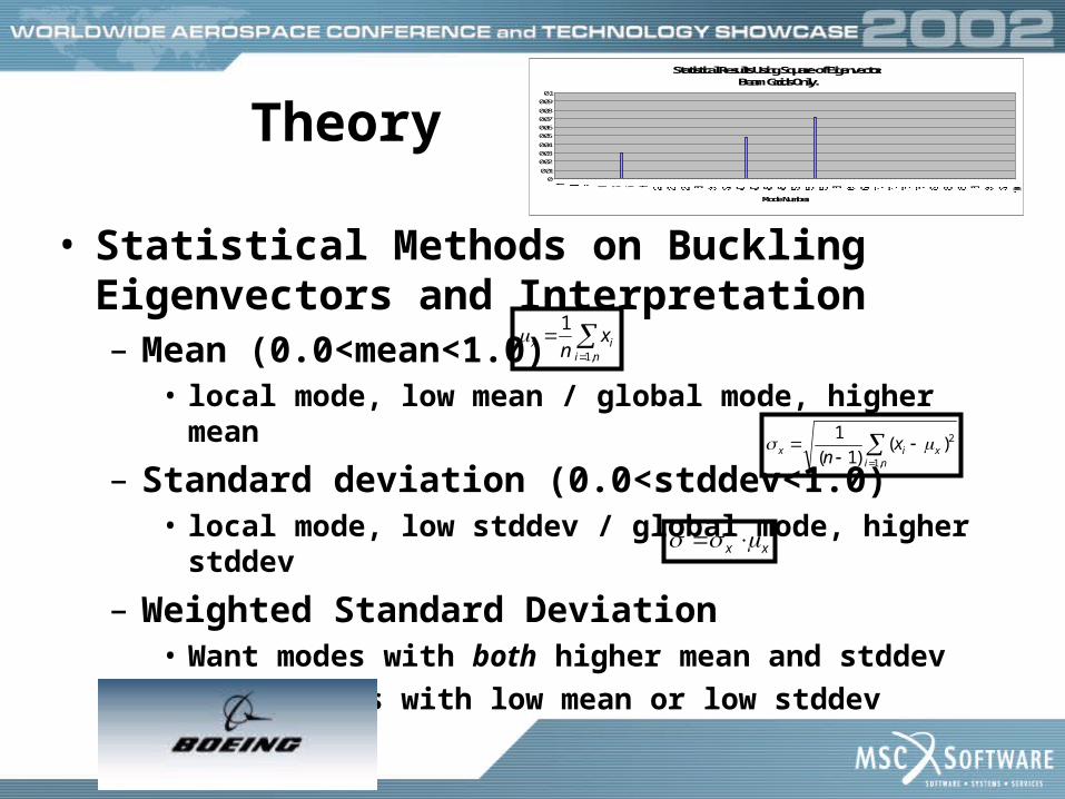
• Statistical Methods on Buckling Eigenvectors and Interpretation– Mean (0.0<mean<1.0)
• local mode, low mean / global mode, higher mean
– Standard deviation (0.0<stddev<1.0)• local mode, low stddev / global mode, higher stddev
– Weighted Standard Deviation • Want modes with both higher mean and stddev• Drops modes with low mean or low stddev
Statistical Results Using Square of Eigenvector.Beam Grids Only.
0
0.01
0.02
0.03
0.04
0.05
0.06
0.07
0.08
0.09
0.1
Mode Number
niix x
n ,1
1
ni
xix xn ,1
2)()1(
1
xx

Computational Strategy
• Convert Eigenvectors to BASIC C.S.– average in the same direction.
• Separate into Translational Components
– high rotation indicate local modes
• Make Eigenvectors positive.
– Absolute Value or Square each term

Computational Strategy• Reduce to a subset of “hard-points”
(optional)
• Compute statistics
– in each direction (X, Y, and Z)
– optionally, statistics on the magnitude
• Print results.

Test CaseStiffened Panel,First 100 Modes(longitudinal compression)

Test Case
Buckling Modes 1, 15, 21, 42, and 57 (in ascending order left to right)
Mode 1,(local)
Mode 15,(1st global)
Mode 21,(mixed/
local)
Mode 42,(1st torsion)
Mode 57,(second
bending)

Test Case ResultsStatistical Results Using Absolute Value of Eigenvector.
0
0.02
0.04
0.06
0.08
0.1
0.12
0.14
Mo d e N u m b e r
Statistical Results Using Square of Eigenvector.Beam Grids Only.
00.01
0.02
0.030.04
0.050.06
0.070.08
0.090.1
Mode Number
Statistical Results Using Square of Eigenvector.
0
0.02
0.04
0.06
0.08
0.1
Mode Number
Statistical Results Using Square of Eigenvector.Intersection Grids Only.
0
0.010.02
0.03
0.04
0.050.06
0.07
0.080.09
0.1
Mode Number

Test Case Conclusions• Squaring Eigenvector prior to statistics
isolates global modes more effectively• Limiting GRIDs to “hard points” identifies
global modes more clearly– More than two orders of magnitude separation
between “global” and “local” modes was observed when squaring eigenvector and using hard points for statistics.

Identifying Fuselage ModesArea of Interest
Frame Configuration of
Fuselage

In general instability, failure is not confined to the region between two adjacent frames or rings but may extend over a distance of several frame spacings… In panel instability, the transverse stiffeners provided by the frames on rings is sufficient to enforce nodes in the stringers at the frame support points… [Bruhn]
Identifying Fuselage Modes
Panel Instability
General Instability
Frame Frame FrameFrame
Skin
Panel Instability
General Instability
Frame Frame FrameFrame
Panel Instability
General Instability
Panel Instability
General Instability
Frame Frame FrameFrame
Skin

Identifying Fuselage Modes
-12000000
-10000000
-8000000
-6000000
-4000000
-2000000
0
2000000
4000000
20 120 220 320 420 520
Fuselage Station
Vertical
Ben
din
g M
omen
t
Critical Load Condition: Running Load of Vertical Bending Moment

Identifying Fuselage Modes
Fine Grid Model
Model Used for Proof of Concept

Identifying Fuselage Modes
M a x i m u m V e r t i c a l M o m e n t - F i r s t G e n e r a l E i g e n v a l u e
- 0 . 5 0
- 0 . 3 0
- 0 . 1 0
0 . 1 0
0 . 3 0
0 . 5 0
0 . 7 0
0 . 9 0
1 6 0 2 0 0 2 4 0 2 8 0 3 2 0 3 6 0 4 0 0 4 4 0
S t a t i o n
Eig
enve
cto
r
M a j o r F r a m e L o c a t i o n s

Identifying Fuselage Modes
0.00E+00
1.00E-06
2.00E-06
3.00E-06
4.00E-06
5.00E-06
6.00E-06
0 200 400 600 800 1000
Mode Number
Me
asu
re
701
Conclusions• A statistical method presented here
quickly identifies the nature of buckling modes for a space frame structure
• Validated on a simple test case.
– Using Eigenvector Square and “hard points” demonstrated better identification and separation of “local” vs “global” modes

Conclusions• Further validated on a model of the
Chinook helicopter.
– The first global mode of the Chinook helicopter was determined by manual sorting of the MSC.Nastran results (mode shape plots), then used to verify the statistical method. The two techniques yielded the same result.

Conclusions• The method showed time savings of three
days to one hour. – Before: mundane manipulation of large data (mode
plots)
– After: simple concise chart (single bar graph)
• Specifying the area of interest yields more conclusive results.
Limitations• Mesh Density/Continuity
– Should be used on a model with reasonably space nodes
– Highly refined regions can skew results
• Good Results for Space Frames and Stiffened Plates– Other models untested, but meeting mesh
density/continuity consideration above, the method should work fine.