Embed Size (px)
Citation preview
A STATE OF THE ART REPORT ON STRUCTURALCONCRETE BLOCK MASONRY
A.R. SANTHAKUMAR
ABSTRACT Masonry is one of mankind's oldest building materials, and one which is leastunderstood. Misconceptions regarding its behaviour has lead, over the years, toa serious misuse of the material through inadequate or even nonexistent designprocedures. Added to this, the poor construction practices have worsened thesituation. However,perhaps.because of considerable amount of information anddata available today, both as to its properties and structural performance, sound
design techniques and. improved manufacturing process, vastly improved construction practices have evolved in the recent years. From the traditional day
blocks, yoer the years, new forms of hollow structural masonry blacks have evol
ved. A wall.doesmo~e than enclosed"'~~..b\lilding in an attractive form. It musthave. strength to support floors a~d roofs and should resist wind and seismiceffects. It must give adequate protection against noise, heat or cold and fire damage.This article traces the history and development of structural hollow blockmasonry.
HISTORICALDEVELOPMENT
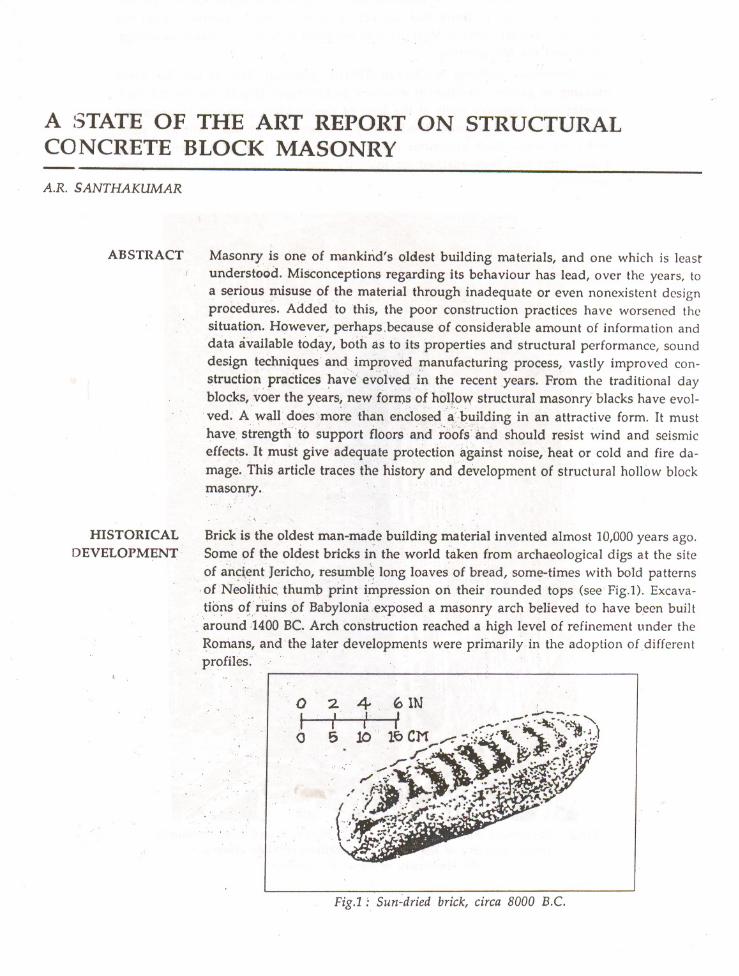
Brick is the oldest man-made building material invented almost 10,000 years ago.
Some of the oldest bricks i~ the world taken from archaeological digs at the site. of ailCi~nt Jericho, resumble long loaves of bread, some-times with bold patternsof Neolithic thumb print· impression on their rounded tops (see Fig.l). Excavations of ruins of Babylonia exposed a masonry arch believed to have been built
. around 1400 Be Arch construction reached a high level of refinement under theRomaris, and' the later developments were primarily in the adoption of differentprofiles.
oto
2. 4r--r5
Fig.l : Sun~dried brick, circa 8000 B.C.
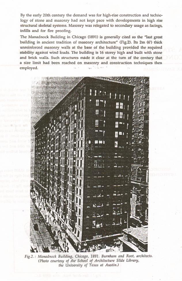
By the early 20th century the demand was for high-rise construction and technology of stone and masonry had not kept pace with developments in high risestructural skeletal systems. Masonry was relegated to secondary usage as facingslinfills and for fire proofing.
The Manadnock Building in Chicago (1891) is generally cited as the "last greatbuilding in ancient tradition of masonry architecture" (Fig.2). Its 2m (6') thickunreinforced masonry walls at the base of the building provided the requiredstability against wind loads. The building is 16 storey high and built with stoneand brick walls. Such structures made it clear at the turn of the century thata size limit had been reached on masonry and construction techniques thenemployed .. ," '." ..
u~--?~Fig.2.: Monadnock Building, Chicago, 1891. Burnham and Root, architects.
(Photo courtesy of .the School of Architecture Slide Library,the University of Texas at Austin.)
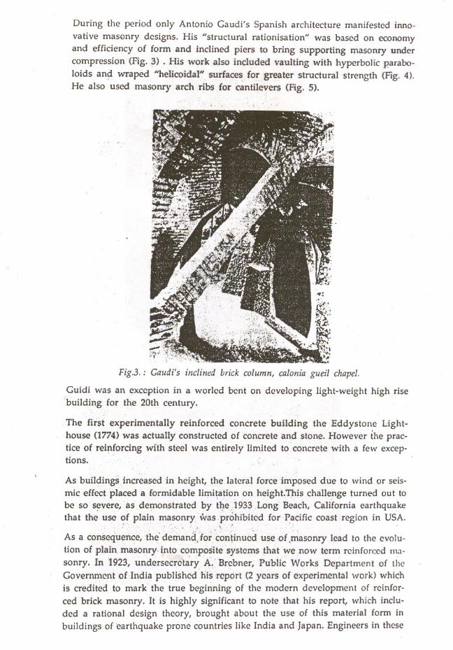
During the period only Antonio Gaudi's Spanish architecture manifested inno
vative mas~mry designs. His "structural rationisation" was based on economyand efficiency of form and inclined pier~ to bring supporting masonry undercompression (Fig. 3) . His work also included vaulting with hyperbolic parabo
loids an~ wraped "helicoidal" surfaces fo~greater structural strength (Fig. 4).He also used masonry arch ribs for cantilevers (Fig. 5).
Fig.3.: Gaudi's inclined brick column, calonia gueilchapel.
Guidi was an exception in a worled bent on developing light-weight high risebuilding for the 20th century.
The first experimentally reinforced concrete building the Eddystone Lighthouse (1774) was actually constructed of concrete and stone. However the practice of reinforcing wIth steel was entirely limited to concrete with a few exceptions.
As buildings increased in height, the lateral force imposed due to wind or seis
mic effect placed a formidable limitation on height.This challenge turned out tobe· so scvere~as.demonstratcd by tl}e1933 .Long Beach, California earthquake
that the use ~f plain m~sonrywa~,~r~hibited for Pacific coast region in USA.As a consequence, .the' demanc({orcon~inued use of .masonry lead to the evolu
tion of plain masonry into composite systems that we .nowterm reinforced masonry. In 1923, undersecretary A~ Brebner, Public Works Department of theGovernment of India published his report (2 years of experimental work) whichis credited to mark the true beginning of the modern development of reinforced brick masonry. It is highly significant to note that his report, which included a rational design theory, brought about the use of this material form inbuildings of 'earthquake prone countries like India and Japan. Engineers in these

FigA.: Wraped masonry roof Sagrada Familia Ch'urch.
Fig.5.: Masonry arch ribs Casa Mila.

countries found that reinforced masonry, if properly constructed offered exec, .ent resistance to seisntic forces. Brcbner indicated that nearly 3 million squarefeet of reinforced brick masonry was constructed in three years prior to 1922.
S. Kanamori, Civil Engineer, Department of Home Affairs, Imperial JapaneseGovernment, reported in July 1930 that "There is no question that reinforcedbrick work should be used instead of unreinforced brick work when any tensilestress would be incurred in the structure. We can make them more safe and
strong, saving much cost. Further, I have found.that reinforced brick work is
more convenient and economical in buildirg t~arreinforccd concrete and what
is still more important, th~rcis, always very ap~reciable saving in time". Thoseearly years of application' included a variety of structures: public, private buildings~ retaining and sea walls, chimneys, bridges and culverts and storage bins.
MODERN TRENDS J The present con.cept ofrCinforced masonry utilises the floors and roofs as diaphragms acting as horizontal flanged gird~rs to distribute lateral loads to wallswhich inturn provide horizontal shear resistance needed in addition to carryingthe normal vertical live and dead loads. This type of structure may be defined
as a box system or shear w"u "ystem. (Fig. 6). These walls if constructed of plainmasonry would be incapable of resisting themagnitude of horizontal shear andbending forces imposed on them. For this reason, modern reinforc~d masonrycontains reinforcing steel to resist the shear and tensile stresses so developed.When these walls are subjected to lateral forces ac~ing normal to them, they behaveas flexural members spanning vertically between floors and horizontally betweenpillasters. Therefore reinforcement must also be provided to develop resistanceon the tension face.
Combined
bearing andshear wall
Floors serveas horizontal,diaphramstransfer windand seismicloads toshear walls
Corridor wall-bearingtransfers lateral loadsparallel to it
Floor/wall connectionmust be capable oftransferring lateral forces
Fig. 6: Concept of shear wall system
Verticalload onwalls usedto developresistance to
overturning

If these techniques and construction methods were available in the olden days,the designers of Monadnock might have used instead of 2m (6'-0") thick only30cm (1'-0") thick or less of masonry walls. Compare that massive stru<:turewith the modern Hanalei Hotel in San Diego, California with only 8 in thickwalls at bottom storey (Fig. n
Fig. 7: Hanalei Hotel, San Diego
MODERN MASONRY Modern masonry may take one of several forms. Structurally, it may be dividedinto load bearing, non load-bearing and Veneer construction. They may be solid
masonry, solid walls of hollow unit or cavity walls. Finally they may be nHnforced, partially reinforced or plain. They may be designed empirically oranalytically.
Load bearing masonry supports its own weight as well as the dead and liveloads of the structure and all lateral wind and seismic forces. Non-load bearing
masonry (including veneers) also resist lateral loads aI1d may support its ownweight for the full height of the structure or be wholely supported by the structure at each floor level. Solid masonry is built of, solid units -Or fully grouted
hollow units in multiple wythes with the collar joint between wythes filled with
mortar or grout. Solid walls of hollow units have open core:s in units but groutedcollar joints. Cavity walls have two or more wythes of solid or hollow units,
separated 'by an open collar joint or cavity (Fig. S).
The concrete masonry manufacturing process consists of six standard phases of
production
1. receiving and storing raw materials
2. batching and mixing
3. moulding unit. shapes
4. curing

(A) SOLID MASONRY WALLS
SOLID WALLS OF HOLLOW UNITS
Tlf'> IN beo JOINT
CAVITY
(C) CAVITY WALL
Fig. 8: Typ~s of Masonry construction

5. cubing and storage and
6. delivery of finished units (Fig. 9).
P.>ATCHINC,
CUP-lING
AND':>TOF-ING
MOLDIN~ UNIT?
LOW - Pltf<7<'UltfC;Tr.AM CU~INC.
CONCRETEMASONRY
STRUCTURALTESTING
HIGH - RISEMASONRY
Fig. 9: Concrete masonry manufacturing process.
Extensive testing of concrete masonry assemblages by various laboratories overa period of many years has established concrete masonry wall construction asa reliable and predictable structural system.
In designs, allowable compressive and flexural stresses are related to ultimate
net compressive strength of masonry f . The value used for the design is gene-m .
rally based on compressive strength test on prisms using the blocks and mortarcontemplated for the job (Fig. 10). If the structure is to have grouted cores, thecores of prisms are filled with grout. Prisms are cured in accordance with the
field practice. After tests the value of fm is calculated by dividing the ultimatetest load by the solid cross sectional area of the prism.
Reinforced masonry bearing walls are ideally ·suited for high-rise construction.The developmellt of high strength masonry block along with improvements ingrouting and reinforcing techniques, have made masonry bearing walls practicalfor su.ch multi-storey construction especially when combined with precast floor~ ,
or roof slabs. The basic concept here involves that of 4-esignirig every floor to
act as a horizontal diaphragm in transferring wind ot seismic loads to transverseshear walls, which in turn carry these forces to the foundation as shown in Fig.11. The shear walls are reinforced to develop the moment and shear forces broughtabout ,through this action.
High-rise ~sonry construction has several desirable features. The important ofthese are:
(i) simplicity of design
(ii) excellent environmental characteristics
(iii) .speed and ease of construction
(iv) reduced building costs

(a) Hollow concrete block prisms
(b) Solid grouted concreteblock prism
(c) Concrete brick prism
Fig. 10: Concrete masonry compression-test prisms

Floors serve ashorizontal
diaphragmstransfer wind
and seismic loadsto shear walls
Corridor wallbearing, transfers
lateral loadsparallel 10 it
Floor wall connectiOI1 mU5t
be capable oftran"sferring
lateral forces. ~/'
EXCELLENTENVIRONMENTAL
CHARACTERISTIC?OF BLOCKMASONRY
Fig. 11: High-rise concept in block masonry
Building may be rectangular square or circular. in plan, however, it is highlydesirable to maintain as much symmetry as possible to preclude difficulties whenproviding seismic resistance.
Since all exterior waIls need not be load-bearing or shear Nsisting, glass or v,e
neers of various types may be used in achieving the desired architect,ural effects.A wide variety of architectural styles and plan layouts are readily qchieved,Such versatility provides for the formation of many interesting patterns in whichmasonry units may be laid. The Holiday Inn Motel, a round bearing waIl structure shown in Fig. 12, provides an excellent example of the versatility.
It would be appropriate at this point to mention briefly some of the qualitiesof the conc~ete block which are superior to conventional brick.
The sound-absorbing qualities of concrete masonry surfaces are rated well abovethe effective levels recommended by sound engineers. Sound transmitted fromroom to room through waIls, ceiling ,and floors, can be minimised through theuse of masonry wall construction.
Reinforced masonry possesses those inherent fire resistance characteristics thatmake the fire ratings for multistorey buildings easily achievable.

CONSTRUCTIONADVANTAGEOUS
VARIOUSAPPLICATION OF
CONCRETE BLOCKMASONRY
Fig. 12: Holiday Inn Motel, a round bearing-wall multi-story 51n;,':;lI,'
In the design of heating and air-condi tioning systems for a bu ild ing, t h: I!,,:' ::1,; iinertia of the building material is important. This means that the iYI3(l':, '.: !,,;,,)('S-;
the ability to reduce the effect of maximum heat gain or loss in cyeli,' ,i~~;:H~L'S,The greater the heat storage capacity (thermal inertia), the sl11illlcrthe in~;;1 '1t:I~('(lUS
rate of flow into the interior (conductivity),
Construction time is minimised, primarily because of typic.11 [,COC!: "';1":'\
of layout. When the walls are placed, floors Ciln be built of(t:riIl3 ,'", :~:li,;ity 0'work. The floors next provide work area reducing the cost of l'xt',,-:e'r scaffolding.
There are no columns or projecting beams to form. The elimination of b(';';n1 n::Juces the floor to floor height by at least 30cm. This could add up to 3m heightfor a 10 storey building.
The structural masonry walls have a surface ,that can be pJi~,ll..'dstaild:"i ',Ir 12ftnatural. No plastering is really required.
Last but not the least, occupancy of lower stories is possible even before upper
stories are completed.
The most common application of concrete masonry is for built-in-placc walls for
buildings of all kinds. However, there are a number of other common applications as described below:
1. One storey commercial buildings: The structural masonry blocks J rc verymuch ·suitable for use in one storey industrial buildings. The typical pbn ofthe industrial building completed with structural masonry block is given in
Fig. 13.

·'.il ;••.•;.',~ ..
Diaphragm level- - - - - - - - -- -- - --_. -.- -- .-. -- - - - -~-1t
Plan
'-
~~-.-
I i I . ~ ~ :r
T . 0
I I ~I 1 •
-il}- .~ .t:I--:. ~. , . ~
1 I I 10
I I i ~.•. .a1 . N
--.-------- .
1
5 bays at 20'-0" " 100',0·
,
1I
~-'
D-----, '4'
I+' .__ h __ •H_+ + ~.~+.---\20' 8' 5' 6' 5' 3' q' 12' j-----,
80'-0"
East wall elevation
Fig. 13: One storey commercial building
2. High rise buildings: High rise buildings have to resist wind and earthquake
using shear walls. The bearing walls also function as shear walls. Fig. 14.shows some examples two directional bearing shear wall layouts. Fig. 15 'shows multidirectional shear/bearing walls used for typical non-rectangularhigh rise structures.
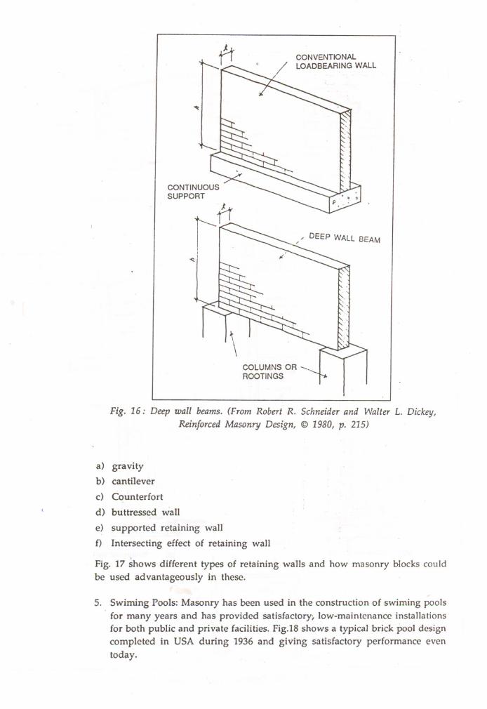
3. Medium rise buildings (up to 4 storeys): In medium ~se bl~i!dings, the con- :cept of deep wall beams are used extensively. The concept is based on wall :spanning between columns or footings instead of having continuous line sup- 1
port (Fig. 16). If soil bearing capacities permit this type of concentrated load'the wall may be d~signed as flexural member. Bearing wall, non load bearing :wall and shear walls may employ this principle to advantage. Deep wallbeams may also be used to advantage to open up the ground floor of a loadbearing structure. The bearing wall on the floor above can be supported oncolumns to act as a deep wall beam and transfer its load to the supports.
4. Masonry retaining wall: There are several basic shapes or forms that are readily adaptable to masonry retaining wall construction. These would includethe following types:

BEARING WALLS
TRANSVERSE SHEAR WALLS
Fig. 14: Some examples of two-directional bearing/shear waIl layouts
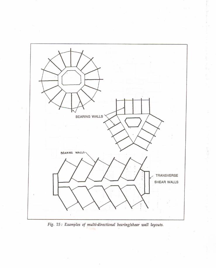
BEARING WALLS
TRANSVERSE
. SHEAR WALLS
Fig. 15: Examples of multi-directional bearing/shear wall layouts,
CONVENTIONALLOADBEARING WALL
CONTINUOUSSUPPORT
DEEP WALL BEAM
~
\COLUMNS OR --,ROOTINGS
Fig. 16: Deep wall beams. (From Robert R. Schneider and Walter L. Dickey,
Reinforced Masonry Design, © 1980, p. 215)
a) gravity
b) cantilever
c) Counterfort
d) buttressed wall
e) supported retaining waIl
f) Intersecting effect of retaining waIl
Fig. 17 shows different types of retaining waIls and how masonry b10cks could
be used advantageously in these.
5. Swiming Pools: Masonry has been used in the construction of swiming pools
for many years and has provided satisfactory; low-maintenance installations
for both public and private facilities. Fig.18 shows a typical brick pool designcompleted in USA during 1936 and giving satisfactory performance even
today.

Propertyline
(a) Gravity wall
(b) Types of cantilever walls
IIII
II.II
-Vertical load(may not always occur.
---.Tension
., .,
Buttressed wall(d)
Load-Compression
strut
----
---
Earth
Lateral earth pressure
Plan
~ ~I'
t Reactions f,.,
Plan
-
-----
Counterfort wall(c)
Fig, 17: Different types of retaining wall

LONGITUDINAL SECTION
TRANSVERSE SECTION
(,. (,. " GolUC.E
WIJ.t Me.,~
WALL SECTION AT DIVING AREA
'>tALAHT,
"
""~" neTALTlt~ 411I(."O.c..ven. t.WO llO~n.
• 1"_ c ,~. o.c. ~0~1t.
('"
WALL SECTION AT SHALLOW AREA
IVARIOUS WALL HEIGHT REQUIREMENTS
H'
Reinforcing steel§
ttLt
(ft)(in.). (ft)Bar sizeSpacing (in)
3.0
103.0No.4 483.5-
103.5No. 5 4840
104.0No. 5 3245
104.5No. 6 325.0
105.0No. 7 325.5
1055No. 5 166.0
106.0No.6 16
t5.5
106.5No. 7 167.0
107.0No.8 167.5
107.5No . .8 16
'Wall h"'ght measured from tall of footing to proposedwater level
tFootlng thickness measured vertically
~Footlng length measured horizontally.§Marn reinforcing steel: vertical steel rn wall bent .nto
footing
Fig, 18; Brick pool design example. (From Brick Institute of America, Technical Note 17K, BIA, McLean, Va.)

~~tf
III
If
11'0.
~ FOUNDATIONSLAB·SECTION A-A
l
j 1'- 411' 1-
x
VERTICALREINE"
+4--+-0+-Z+-~4--
•...•
+-0('+-"'-:=~..-
.~+---0+--:z:-~+-- ••.:=£~~-4--+--Q-z:::~- ...._i:=s
>"-1':
t--tinI I I
I 'I I, I: I," AA I
mJ
I
II
I
r-TI
I
~ /')
I1/ I'.>
I!
ELEVATION SECTION B-B DETAIL
.---.-----.-----------------------------------J~ !I."
Fig. 19: Reinforced masonry industrial chimney
j
·1
I
4'
it
1,j1
ie, Of! /.4' rJI;"?CE 1Ai')! ~ '::.
/(fOUII1W tM~tr)'"1E.tlf·':lEt TAI':>LE C
t
--------.------ WALL SPAN I~ ...ill,:q j,.----t - ...
, . ~\'$\\\"''''''''\\\\'"\\'1\\\\ \,\\\\ \\ ''''''.,. ~.. ' _':~ .~" I~'()!l. II.' . ':>~E iArJlE I'.> /- ~\«~\<\\< .", -'- ', .. , " . L
PLAN \ rWALL SAPN
ELEVATION SECTION ALTERNATE PIERS
Fig. 20.a: Brick pier-and-panel garden walls.
(From Brick Institute of America, Technical Note 29A, BIA, McLean, Va)
LEANTH 21'-6"
WAI.L PLAN
(A) BRICK WALL
';t..-CItAOe N ~LOCj(.O~ CA~l·\N,pL.ACeCONe., beLOW GllAoe
WALL ';lC.TloN
(B)
WALL SECTION
WALL PLAN
CONCRETE BLOCK WALL
Fig. 20.b : Serpentine walls. (From Brick Institute of America, Technical Note 29A, BIA, McLean, Va..;and Frank A. Randall and- William C. Panarese, Concrete Masonry Handbook for Architects, Engineers,
and Builders, Portland Cement Association, Skokie, Ill" 1976,)
CONCLUSION
REFERENCES
6. Chimney: Even commercial chimney of nearly 25m height has been success·
fully built with concrete block masonry. Fig. 19 shows the example of aReinforced masonry industrial chimney completed and functioning satisfa·corily.
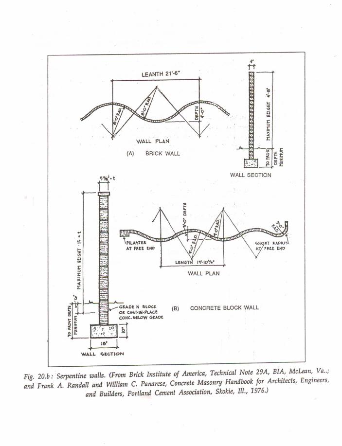
7. Compound walls: Brick garden walls may take different forms. A straight
wall with pillasters must be designed with reinforcements. Fig.2I9.a. showsBrick pier and panel garden -wall. Serpentine and folded plate wall provide
more lateral 'stability. A typical serpentine wall is shown in Fig.20. b.
The structural concrete block masonry has innumerable applications. Its paten·
tia~ has been exploited only to a limited extent in India. In the years to come,more applications are bound to come to the fore. The applications are only limited by designers imagination and use of this versatile material.
1. Christine Beall, Masonry Design and Detailing for Architects, Engineers and
Builclers, Prentice-Hall Englewood chiffs, New Jersey, 1984.
2. Frank A Randall and William C. Panarese "Concrete Masonry" Hand book
for Architects, Engineers and Builders, Portland Cement Association, Illinois1976.
3. Robert. R. Schneider and Walter L. Dickey"Reinforced Masonry Design",prentice-Hall Englewood cliffs, New Jersey, 1987.


![V ^`XcWdjimTa]bY[h - Wing On Travel · `jgou[ irls@j gpxi[q,m\pji\][culpoj gwktxx grkrxx l `jgou\ ir@j gpxi[q,m]pji\][culwj gwksxx grkrxx l `jgou] iq@j gpxi[q,m]qn]rji\][culpokpqj](https://img.dokumen.tips/doc/110x75/5cf97b8088c99315288c576e/v-xcwdjimtabyh-wing-on-travel-jgou-irlsj-gpxiqmpjiculpoj-gwktxx.jpg)