Embed Size (px)
Citation preview

Chapter IV
AOD Processing
Some claim the introduction of the AOD Process for
the refining of specialty steels and alloys represents
the most significant advance in the manufacture of
these materiais. The five and six-hour heat times
associated with producing a final carbon content below
0.030% in the electric are furnace have been replaced
by routine production of extra-low carbon (ELO
stainless heats in less than two hours in the AOD
vessel.
The production of an aircraft guality low-alloy
heat in the are furnace. with its sluggish slag-metal
reactions, hás been replaced by a four-minute reduction
(deoxidation) stir in an AOD vessel. Twenty years ago,
extensive furnace deoxidation procedures, coupled with
lime-magnesium injection, were required to make 0.005%
maximum sulfur. Today, even 0.001% sulfur can easily
be produced with AOD.
Given below are generalized processing techniques
for stainless steel and for low-alloy EAF-AOD
duplexing. These are not intended as rigorous
practices, but rather to give an overview of AOD
procedures. It should be noted that AOD vessels accept
molten metal transfers from not only electric are
furnaces, but have also routinely treated molten steel
(or ferroalloys) from: induction furnaces, LD (or BOP)
converters, and submerged are smelting furnaces. On an
intermittent basis, metal from hot metal sources
including blast furnaces and cupolas have also been
refined in AOD vessels.
A. Stainless Steel
o Electric Are Furnace (EÃF)
Accurate end-point control begins in the EAF.
That statement is not surprising, but it deserves
emphasis. It is very easy to relax attention
given to the electric furnace when an AOD vessel
is introduced, The quality of the furnace charge
is almost always decreased after the installation
of an AOD unit, even while product specifications
are being tightened. Raw materiais charged to the
furnace should be selected on the basis of least
cost, AOD-refined steel. In general, alloying
elements such as manganese, chromiun, nickel and
molybdenum are charged to melt in very close to
specification requirements. The carbon content of
the hot metal transferred to the AOD vessel will
be a function of the scrap:alloy ratio which in
turn is dependent on rei ative economics and/or
residual element (e.g., phosphorus. copper,
cobalt) requirements. EAF silicon leveis at tap
should be sufficient to ensure good metallic
reduction but not só high to result in severe AOD
lining wear; typical aim tap silicon contents
range from 0.15-30%.
The objective for the EAF is to miníinize
metallic oxidation of chromium, manganese. iron,
etc. during melt-down and provide a fluid bath as
quickly as possible for transfer to the AOD.
Oxygen can be used to assist in melting, bath
homogenization, temperature incrense and also to
control silicon content.
Details of the electric are furnace practice
will vary from shop to shop depending on furnace
configuration, heat size, charge make-up, and
power costs. The bath temperature mus t be
elevated to a levei sufficient to provide hot
metal in the AOD vessel at roughly 2800"F
(1540°C). The degree of super-heat required in
the EAF is a function of the temperature loss
during tapping, transfer activities and charging
• ••
• • • :
.•;•
l
PNEUMATIC STEELMAKING - VOLUME TWO - 15

to lhe vessel. TM s again will vary by shop vi th
the number of furnaces involved, transfer l adi e
refractory composition, and transfer ladle and
vessel preheat. EAF tap temperatures between
3000°F (1650°C) and 3100°F (1700°C) are common.
A typical EAF practice would be to melt-down
under a basic, reducing slag, followed by a
chemistry sample to determine melt-down silicon
levei. Quite possibly the chemical analysis will
be extensive to determine the levei of tramp and
residual elements and to verify that major
alloying elements are within acceptance limits.
An oxygen blow may be used to lower the silicon
levei and raise the temperature. The bath is
heated to tap temperature and tapped into the
transfer ladle.
o Transfer Ladle
Before transferring the molten metal to the
vessel, the furnace slag is coimonly removed as
completely as practical. Slag carried into the
refining vessel and not removed before
decarburization will result in unpredictable final
composition and will adversely effect AOD lining
life.
Deslagging can be performed from either the
furnace and/or the transfer ladle, depending on
shop layout. If silicon is to be added for alloy
recovery, then deslagging from the ladle is
preferable, to take advantage of tap stream
•ixing. In some cases, are furnace slag is
transferred with the crude stainless steel into
the AOO vessel and is first stirred for alloy
recovery and then the slag is removed prior to the, . , , (64)start of decarburization
After slag removal, the ladle plus metal and
any renaining slag is weighed. An accurate
weighing method is desirable since this
measurenent will directly affect the subseguent
processing calculations.
At some point during the transfer cycle, a
chemistry sample is obtained. This complete
analysis is used as the starting composition for
AOD processing.
o AOD
Stainless production in the vessel can be
broken into three phases as summarized below:
i) Decarburization
- From any carbon levei to specification
levei
- Control of bath temperature
- Additions to adjust heat weight, bath
and slag composition, and control
temperature
ii) Reduction/Desulfurization
- Recover virtually ali oxidized
metallies
- Degas
- Sulfur control to any levei from
0.001% to 0.020% with a single or
double slag practice as appropriate
iii) Trii
- Minor adjustments to chemistry and
temperature
i) Decarburization
Once the heat hás been transferred to the AOD
vessel, bath temperature is usually sampled.
Based on the starting temperature, chemistry and
weight, a series of calculations to guide
processing is made either by the operator or by
computer. Results of these calculations include:
- Amount and timing of alloy additions
- Duration of a given oxygen:inert gás
ratio
- Inert gás selection (nitrogen or
argon)
- Estimated quantity of reduction
material required
16 - PNEUMATIC STEELMAKING - VOLUME TWO
The above determinatíons are lade within the
constraints of temperature control below some
upper limit (e.g., 3100°F or 1700°C), minimization
of metallic oxidation, and composition adjustients
to aim analysis.
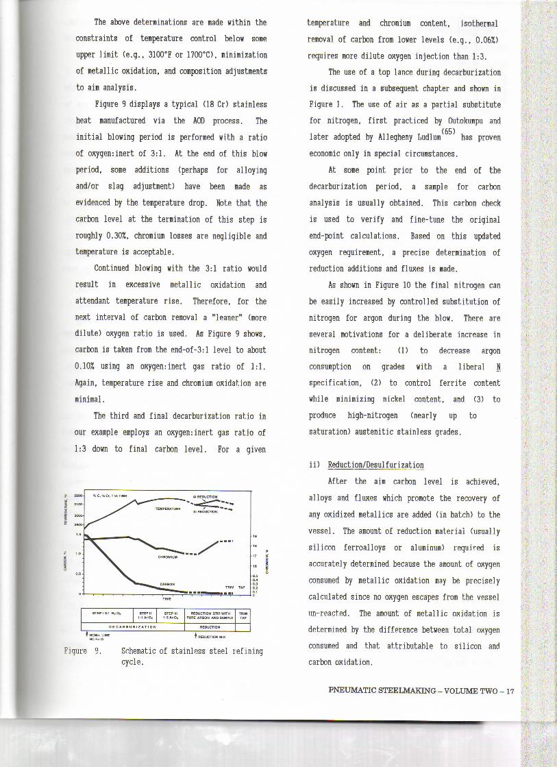
Figure 9 displays a typical (18 Cr) stainless
heat manufactured via the AOD process. The
initial blowing period is performed with a ratio
of oxygen:inert of 3:1. At the end of this blow
period, some additions (perhaps for alloying
and/or slag adjustient) have been made as
evidenced by the temperature drop. Note that the
carbon levei at the teriination of this step is
roughly 0.30%, chromium losses are negligible and
temperature is acceptable.
Continued blowing with the 3:1 ratio would
result in excessive letallic oxidation and
attendant temperature rise. Therefore, for the
next interval of carbon removal a "leaner" (more
dilute) oxygen ratio is used. As Figure 9 shows,
carbon is taken from the end-of-3:l levei to about
0.107, using an oxygennnert gás ratio of 1:1.
Again, temperature rise and chromium oxidation are
minimal.
The third and final decarburization ratio in
our example employs an oxygen:inert gás ratio of
1:3 down to final carbon levei. For a given
STEP 1 3:1 N2:Ox STEP II1 :1 AnOx
STEP III1 :3 Ar:0x
DE C A R B U R I Z AT l 0 N
REDUCTlON STIRWITHPURÉ ARGON AND SAMPLE
REDUCTlON
TRIMTAP
T HCMn, LIMEHC Fe Cr
REDUCTlON MIX
Figure 9. Schematic of stainlnss steel refiningcycle.
temperature and chromium content, isothermal
removal of carbon from lower leveis (e.g., 0.06%)
requires more dilute oxygen injection than 1:3.
The use of a top lance during decarburization
is discussed in a subsequent chapter and shown in
Figure 1. The use of air as a partial substitute
for nitrogen, first practiced by Outokumpu and
later adopted by Allegheny Ludlum ' hás proven
economic only in special circumstances.
At some point prior to the end of the
decarburization period, a sample for carbon
analysis is usually obtained. This carbon check
is used to verify and fine-tune the original
end-point calculations. Based on this updated
oxygen requirement, a precise determination of
reduction additions and fluxes is made.
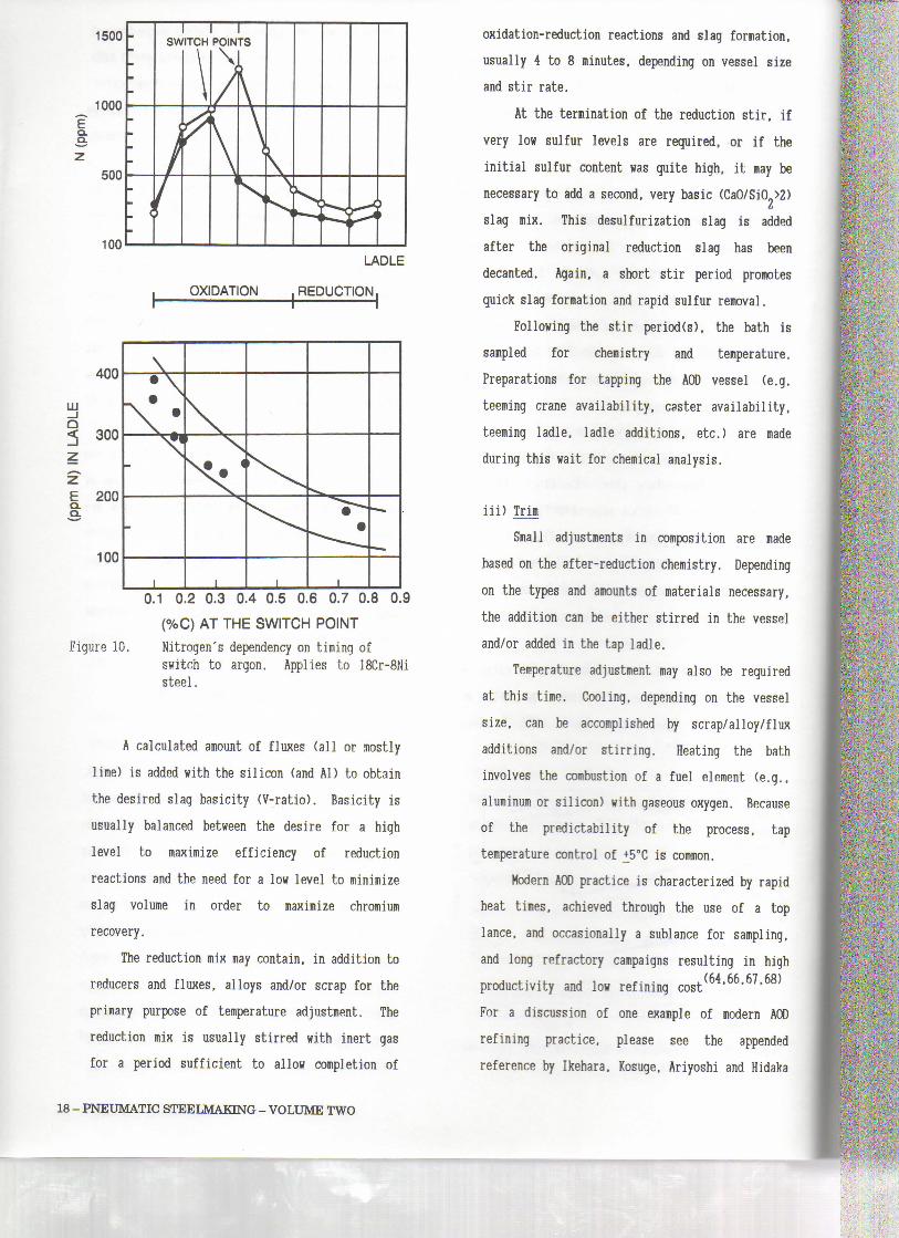
As shown in Figure 10 the final nitrogen can
be easily increased by controlled substitution of
nitrogen for argon during the blow. There are
several motivations for a deliberate increase in
nitrogen content: (1) to decrease argon
consumption on grades with a liberal N
specification, (2) to control ferrite content
while minimizing nickel content, and (3) to
produce high-nitrogen (nearly up to
saturation) austenitic stainless grades.
ii) Reduction/Desulfurization
After the aim carbon levei is achieved,
alloys and fluxes which promote the recovery of
any oxidized metallics are added (in batch) to the
vessel. The amount of reduction material (usually
silicon ferroalloys or aluminim) required is
accurately determined because the amount of oxygen
consumed by metallie oxidation may be precisei y
calculated since no oxygen escapes fron the vessel
un-react.ed. The amount of metal lie oxidation is
determined by the difference between total oxygen
consumed and that attributable to silicon and
carbon oxidation.
PNEUMATIC STEELMAKING - VOLUME TWO - 17
1500 -
1000
Q.Q.
LADLE
OXIDATION .REDUCTION.
IllQ
400
300
E 200CLQ.
100
\1 0.2 0.3 0.4 0.5 0.6 0.7 0.8 0.9
(%C) AT THE SWITCH POINT
Figure 10. Nitrogen's dependency ou timing ofswitch to argon. Applies to 18Cr-8Nisteel.
A calculated amount of fluxes (ali or mostly
lime) is added with the silicon (and Al) to obtain
the desired slag basicity (V-ratio). Basicity is
usually balanced between the desire for a high
levei to maximize efficiency of reduction
reactions and the need for a low levei to minimize
slag volume in order to maximize chromium
recovery.
The reduction mix may contain, in addition to
reducers and fluxes, alloys and/or scrap for the
primary purpose of temperature adjustment. The
reduction mix is usually stirred with inert gás
for a period sufficient to allow completion of
oxidation-reduction reactions and slag formation,
usually 4 to 8 minutes, depending on vessel size
and stir rate.
At the termination of the reduction stir, if
very low sulfur leveis are required, or if the
initial sulfur content was quite high, it may be
necessary to add a second, very basic (CaO/SiO >2)ti
slag mix. This desulfurization slag is added
after the original reduction slag hás been
decanted. Again, a short stir period promotes
quick slag formation and rapid sulfur removal.
Following the stir period(s), the bath is
sampled for chemistry and temperature.
Preparations for tapping the AO) vessel (e.g.
teeming crane availability, caster availability,
teeming ladie, ladie additions, etc.) are made
during this wait for chemical analysis.
iii) Trim
Small adjustments in composition are made
based on the after-reduction chemistry. Depending
on the types and amounts of materiais necessary,
the addition can be either stirred in the vessel
and/or added in the tap ladle.
Temperature adjustment may also be required
at this time. Cooling, depending on the vessel
size, can be accomplished by scrap/alloy/flux
additions and/or stirring. Heating the bath
involves the combustion of a fuel element (e.g.,
aluminum or silicon) with gaseous oxygen. Because
of the predictability of the process, tap
temperature control of +5°C is common.
Modera AOD practice is characterized by rapid
heat tires, achieved through the use of a top
lance, and occasionally a sublance for sampling,
and long refractory campaigns resulting in high
productivity and low refining cost(64>66>67>68)
For a discussion of one example of modern AM)
refining practice, please see the appended
reference by Ikehara, Kosuge, Ariyoshi and Hidaka
l
18 - PNEUMATIC STEELMAKING - VOLUME TWO

which describes Nippon Steel 's operation . The
flexibility of the AOD process is displayed by
Pacific Metals refining of liquid high carbon
ferrochromium and ferronickel to low carbon
stainless steel in their 30 ton AOD vessel. A
complete description of this operation is covered
in the appended reference by Yamada, Azuma, Hiyama
and Nishimae . AOD operation in a specialty
steel shop, producing both stainless and tool
steels, often demands varying heat sizes and
severe compositional restraints which are reviewed
(70)Byrnes
The use of small AOD vessels in foundries,
especially investment foundries, leads to special
operating concerns, including the need for a
movable vessel to minimize the heat loss
associated with transfer. A description of small
vessel operation is covered in the appended. (71)reference by Sarlitto
B. LovhAllox
The melt-down of EAF charges of carbon/ low-
alloy grades for subsequent AOD refining can be
performed with one of two techniques: (1)
completely open, with the addition of ore. scale
or oxygen to dephosphorize (and oxidize chromium
and manganese), or (2) dead-melted for the
retention of ali metallics. In the latter case,
composition is controlled to specification aims
for most elements, with the exception of carbon
and silicon. The choice between these EAF
procedures depends, in part, on scrap composition
relative to specification requirements, but mainly
on the need for dephosphorization. The transfer
ladle practice for these grades is similar to that
described for stainless transfers, Slag removal
prior to vessel charging is especially criticai if
reversion from an oxidizing, phosphorus-bearing
slag is to be avoided,
Starting carbon and silicon contents in the
vessel as well as the timing of adjustments to the
starting carbon and silicon are determined by heat
size, EAF practices, transfer temperatura,
composition and quality requirements, and other
shop-specific circumstances. For these grades,
the blowing schedule is simplified to a single,
oxygen-rich (3:1) ratio. This ratio is used for
two purposes:
- Decarburization (generally at least 0.2 -
0.4% carbon for degassing)
-lemperáture élevation íhrough oxidation of
a fuel element
After decarburization and initial fueling, a
"reduction" desulfurization mix (if necessary) is
stirred for two to three minutes. Following
sampling of chemistry and temperature, final
adjustments to chemistry and temperature are made
and the heat is tapped. Typical single-slag
low-alloy heats, as shown in Figure 11, have AOD
heat times of 25-40 minutes.
Temperature control during AOD refining is
accomplished by controlling the peak temperature
at the end of the oxygen blow (see Figure 11).(72)Data in Figure 12 for a 40-ton vessel indicate
that on 95% of AOD heats sufficient temperature is
reached at that stage to enable the heat to coast
T,°F3000
2900
2800
T Ur—3n 02/Ar -j-J C/J Ur—Ar » |« Chsm —»J . Ai
TRIM
Tap
O 5 10 15 20 25 30
TIME, min.
0.50
0.40
0.30
0.20
0.10
0.00
Figure 11. Schematic of carbon/low-alloy refiningcycle.
PNEUMATIC STEELMAKING - VOLUME TWO - 19

LUXLLOLU
lLU
PEAK TEMPERATURE CONTROLAIM
83%
5%12%
<2960 2960-2990
TEMPERATURE, °F
>2990
down to tap temperatura. Only 5% of the heats,
plus any heats which are delayed by other problems
in the shop such as a crane outaqe, need to be
reblown. For small vessels, especially those
smaller than 10 tons. a reheat step prior to tap
may be required. Final teeminq temperature
control of +8°F is achieved on carbon and low
alloy steels ingot teemed at 2816°F.
Figure 12. Peak Temperature Control. (Andreini andFarmer (77))
20 - PNEUMATIC STEELMAKING - VOLUME TWO