Embed Size (px)
Citation preview
A Small 4-wheeler EV Propulsion System UsingDTC Controlled Induction Motor
Deepak Ronanki, A Hemasundar and P Parthiban, Member, IEEE
Abstract—With the increasing need of electric vehicles (EV),necessary development is required to get reliable, efficient andeconomical drives for electric propulsion. Electric propulsionsystem using Induction Motor drive (IM) is becoming sopopular because of its reliability, technological maturity andlow cost. Field Orientation Control (FOC) is so popular incontrolling the IM, but it has disadvantages like sensitive toparametric variation, external disturbance, load variation andalso algorithm takes more time for execution, hence it requiresa very fast microprocessor with high millions of instructionsper second (MIPS) for implementation. In this paper, IM iscontrolled by using Direct Torque Control (DTC) techniquebecause of its simple configuration and gives quick response.The mathematical model takes into account of the inverter, IMdynamics and vehicle aerodynamics. In this paper, the responseof the IM with DTC for EV load for driving cycle consists ofstarting, acceleration, constant speed and deceleration modesare explained and validated using MATLAB/SIMULINK.
Index Terms—Direct Torque Control (DTC), Electric Vehicle(EV), Induction Motor (IM), MATLAB
I. INTRODUCTION
IN developing countries like India, urban transportation isthe prime issue on environmental and economic aspects.
Air pollution, global warming, the rapid depletion of theearth’ s petroleum resources and also rapid increase infuel rate are the major concerns, so there is a need todevelop an efficient, clean and safe transportation. EVis only an alternative to replace conventional InternalCombustion Engine (ICE) for urban transportation since ithas advantages like high efficiency, free from petroleum,absence of emissions, quiet and smooth operation [1].
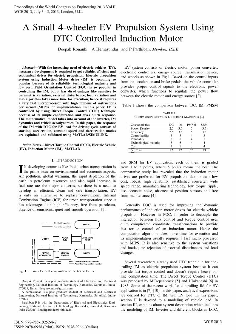
Fig. 1. Basic electrical composition of the 4-wheeler EV
Deepak Ronanki is a post graduate student of Electrical and ElectricalEngineering, National Institute of Technology Karnataka, Surathkal, India-575025, Email: [email protected].
A hemasundar is a post graduate student of Electrical and ElectricalEngineering, National Institute of Technology Karnataka, Surathkal, India-575025.
Parthiban P is with the Department of Electrical and Electronics Engi-neering, National Institute of Technology Karnataka, surathkal, KarntakaIndia-575025, Email:[email protected].
EV system consists of electric motor, power converter,electronic controllers, energy source, transmission device,and wheels as shown in Fig.1. Based on the control inputsfrom the accelerator and brake pedals, the vehicle controllerprovides proper control signals to the electronic powerconverter, which functions to regulate the power flowbetween the electric motor and energy source [2].
Table I shows the comparison between DC, IM, PMSM
TABLE ICOMPARISON BETWEEN DIFFERENT MACHINES [3]
Characteristics DC IM PMSM SRMPower Density 2.5 3.5 5 3.5Efficiency 2.5 3.5 5 3.5Controllability 5 5 4 3Reliability 3 5 4 5Technological maturity 5 5 4 4Cost 4 5 3 4∑
Total 22 27 25 23
and SRM for EV application, each of them is gradedfrom 1 to 5 points, where 5 points means the best. Thecomparative study has revealed that the induction motordrives are preferred for EV propulsion, due to their lowcost, robust, high reliability, established converter, widespeed range, manufacturing technology, low torque ripple,less acoustic noise, absence of position sensors and freefrom maintenance [4].
Generally FOC is used for improving the dynamicperformance of induction motor drives for electric vehiclepropulsion. However in FOC, in order to decouple theinteraction between flux control and torque control usesquite complicated coordinate transformations to providefast torque control of an induction motor. Hence thecomputation algorithm takes more time for execution andits implementation usually requires a fast micro processorwith MIPS. It is also sensitive to the system variationsand inadequate rejection of external disturbances and loadchanges.
Several researchers already used DTC technique for con-trolling IM as electric propulsion system because it canprovide fast torque control and doesn’t require heavy on-line computation time. The Direct Torque Control (DTC)was proposed by M.Depenbrock [5] and I.Takahashi [6] in1985. Some of the recent work for controlling IM for EVapplication is in [7]-[10]. In this paper, analytical expressionsare derived for DTC of IM with EV load. In this paper,section II is devoted to a modeling of vehicle load. Insection III, explains about system description which includesthe modeling of IM, Inverter and different blocks in DTC.
Proceedings of the World Congress on Engineering 2013 Vol II, WCE 2013, July 3 - 5, 2013, London, U.K.
ISBN: 978-988-19252-8-2 ISSN: 2078-0958 (Print); ISSN: 2078-0966 (Online)
WCE 2013
Simulation results for DTC of IM in acceleration mode,constant speed mode and deceleration modes are presentedin section IV.
II. VEHICLE MODEL
The straight line motion of a vehicle can be approximatelymodeled using following equation [1]
mdv
dt= Ft − ΣFr (1)
where,v=speed of the vehicle (m/s)m=mass of the vehicle (kg)Ft=Tractive effort of the vehicle (N)Fr are the forces resisting vehicle’s motion. These include:• Force due to rolling friction of the tyres with the road
surface given by
Ffriction = µrmgcosθ (2)
where, µr=coefficient of rolling friction, g=9.8m/s2=gravitational acceleration.
• Aerodynamic drag as vehicle tries to move through airgiven by
Fdrag =1
2CdρAv
2 (3)
where, Cd=coefficient of drag, A=aerodynamic refer-ence area (m2), ρ=density of air (1.2 kg/m3 at 20oc).
• Grading resistance when vehicle tries to climb up ordown the slope. The mass of a vehicle creates compo-nent given by
Fgradient = mgsinθ (4)
In case of electric vehicle, the relation between vehicle speedto motor speed (rpm) is given by
v =πNmr
30Gηt(5)
where, r=wheel radius, G=gear transmission ratio,ηt=transmission efficiency (0.97 to 0.98).Substituting all above equations in equation (1), the overalldynamic equation of motion of the vehicle on flat road isgiven in [1] is
(m+J
r2)dv
dt=Tmr− µrmg −
1
2CdρAv
2 (6)
where, J=moment of inertia of vehicle, it can be accountedfor by increasing the mass by 5% [11].Using the equations (5 & 6), the vehicle load is modeledin the Matlab/simulink. The power rating (Pm) of the motorcan be given by
Pm = Ftv = Tm2πNm
60(7)
For the max speed of 80 kmph, the motor rating is obtainedas 2.1 kW
III. SYSTEM DESCRIPTION
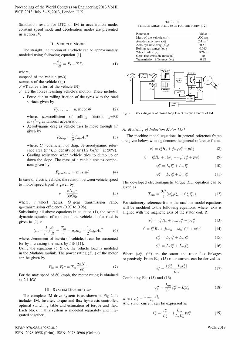
The complete IM drive system is as shown in Fig 2. Itincludes IM, Inverter, torque and flux hysteresis controller,optimal switching table and estimation of torque and flux.Each block in this system is modeled separately and inte-grated together.
TABLE IIVEHICLE PARAMETERS USED FOR THE STUDY [12]
Parameter ValueMass of the vehicle (m) 500 kgAerodynamic area (A) 2.4 m2
Aero dynamic drag (Cd) 0.51Rolling resistance (µr) 0.015Wheel radius (r) 0.26mGear Transmission Ratio (G) 10Transmission Efficiency (ηt) 0.98
Fig. 2. Block diagram of closed loop Direct Torque Control of IM
A. Modeling of Induction Motor [13]
The machine model equations in general reference frameare given below, where g denotes the general reference frame.
vgs = igsRs + jωgψgs + pψgs (8)
0 = igrRr + j(ωg − ωg)ψgr + pψgr (9)
ψgs = Lsigs + Lmi
gr (10)
ψgr = Lrigr + Lmi
gs (11)
The developed electromagnetic torque Tem equation can begiven as
Tem =3P
4(ψgsdi
gsq − ψgsqi
gsd) (12)
For stationery reference frame the machine model equationswill be modified to the following equations, where axis isaligned with the magnetic axis of the stator coil, R.
vαs = iαsRs + jωαψαs + pψαs (13)
0 = iαrRr + j(ωα − ωα)ψαr + pψαr (14)
ψαs = Lsiαs + Lmi
αr (15)
ψαr = Lriαr + Lmi
αs (16)
Where (ψαs , ψαr ) are the stator and rotor flux linkagesrespectively. From Eq. (15) rotor current can be derived as
iαr =(ψαs − Lsiαs )
Lm(17)
Combining Eq. (15) and (16)
ψαs =LmLr
ψαr + L∗siαs (18)
where L∗s =LsLr−L2
m
Lr
And stator current can be expressed as
iαs =ψαsL∗s− (
LmLrL∗s
)ψαs (19)
Proceedings of the World Congress on Engineering 2013 Vol II, WCE 2013, July 3 - 5, 2013, London, U.K.
ISBN: 978-988-19252-8-2 ISSN: 2078-0958 (Print); ISSN: 2078-0966 (Online)
WCE 2013

The developed electromagnetic torque Tem equation can begiven as
Tem =3P
4
LmLrLs
(ψαs × ψαs ) (20)
Tem =3P
4
LmLrLs
(|ψαs ||ψαs |sinα) (21)
where α = δs − δr denotes the angle between them whilerotating in synchronous speed.The mechanical torque equation can be given as
Fig. 3. Phasor diagram of stator and rotor flux linkage space vector
Tem − TL = Jdω
dt+Bω (22)
B. Inverter Modeling
Fig.4 shows the inverter which supplies the input voltagefor the three phases of IM assuming that it is star connected.Each phase leg comprises of two power semiconductordevices.
Fig. 4. Three phase IGBT based Inverter
VAo = (S1) ∗ Vdc2− (S6) ∗ Vdc
2(23)
VBo = (S3) ∗ Vdc2− (S4) ∗ Vdc
2(24)
VCo = (S5) ∗ Vdc2− (S2) ∗ Vdc
2(25)
where VAo, VBo & VCo are pole voltages
VAN =2
3VAo −
1
3VBo −
1
3VCo (26)
Similarly for the other phases VBN & VCN where VAN ,VBNand VCN are line-neutral voltages and Vdc is dc-link voltageHere we assumed switch-on state for upper switches istreated as 1 and lower switches as -1.
C. Torque and Flux hysteresis comparatorsIn this block, the reference and estimated values of torque
and flux linkage vector are compared. If the reference torqueis larger than the actual value, the comparator output as state1 or otherwise -1. If the reference flux is larger than actualvalue, the comparator output state 1 or otherwise 0.
Fig. 5. Torque and Hysteresis Comparators
D. Optimal switching Table
Fig. 6. Definition of voltage vectors and sectors
The estimated torque and flux values are compared withthe reference values, the error is compared in hysteresiscomparator and the output of the comparators along with theflux vector angle (θ) are together used in switching table todetermine the appropriate voltage vector. The voltage vectorobtained from the switching table is then applied to theVoltage Source Inverter (VSI). The phase voltages can berepresented in switch states and space vector for voltage as
vs =2
3V (Sa + Sb exp j
2Π
3+ Sc exp−j 2Π
3) (27)
Where vs is the primary voltage space vector, Sa, Sb andSc represent three-phase switching states.
There are six active vectors V1 to V6 which are apartfrom 60o in space and the two zero voltage vectors V0 andV7 are located in the center of the space-vector plane. Fora stator flux space vector that lies in the kth sector, thevoltage vectors vk, vk+1 and vk−1 are chosen to increase themagnitude of the flux vk+2, vk−2 and vk−3 can be chosen todecrease the flux magnitude [13]. In general, switching tableis shown in Fig.7.
Proceedings of the World Congress on Engineering 2013 Vol II, WCE 2013, July 3 - 5, 2013, London, U.K.
ISBN: 978-988-19252-8-2 ISSN: 2078-0958 (Print); ISSN: 2078-0966 (Online)
WCE 2013
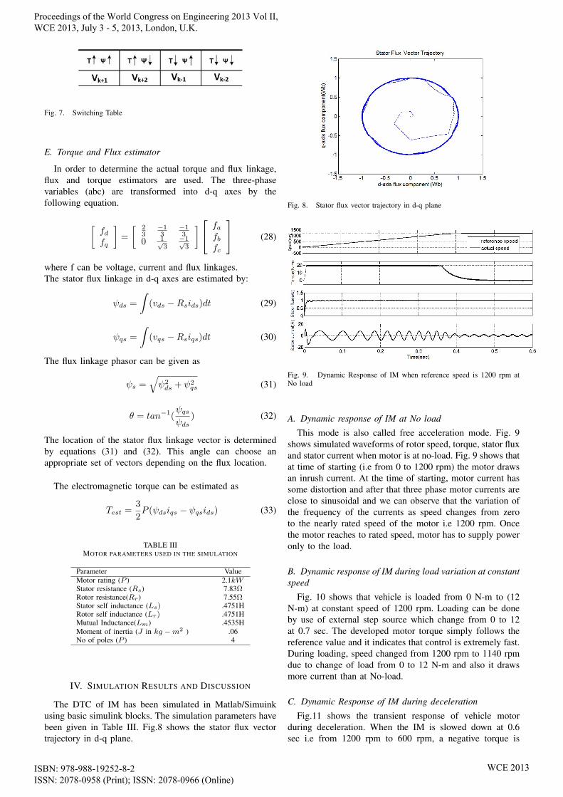
Fig. 7. Switching Table
E. Torque and Flux estimator
In order to determine the actual torque and flux linkage,flux and torque estimators are used. The three-phasevariables (abc) are transformed into d-q axes by thefollowing equation.
[fdfq
]=
[ 23
−13
−13
0 1√3
−1√3
] fafbfc
(28)
where f can be voltage, current and flux linkages.The stator flux linkage in d-q axes are estimated by:
ψds =
∫(vds −Rsids)dt (29)
ψqs =
∫(vqs −Rsiqs)dt (30)
The flux linkage phasor can be given as
ψs =√ψ2ds + ψ2
qs (31)
θ = tan−1(ψqsψds
) (32)
The location of the stator flux linkage vector is determinedby equations (31) and (32). This angle can choose anappropriate set of vectors depending on the flux location.
The electromagnetic torque can be estimated as
Test =3
2P (ψdsiqs − ψqsids) (33)
TABLE IIIMOTOR PARAMETERS USED IN THE SIMULATION
Parameter ValueMotor rating (P ) 2.1kWStator resistance (Rs) 7.83ΩRotor resistance(Rr) 7.55ΩStator self inductance (Ls) .4751HRotor self inductance (Lr) .4751HMutual Inductance(Lm) .4535HMoment of inertia (J in kg −m2 ) .06No of poles (P ) 4
IV. SIMULATION RESULTS AND DISCUSSION
The DTC of IM has been simulated in Matlab/Simuinkusing basic simulink blocks. The simulation parameters havebeen given in Table III. Fig.8 shows the stator flux vectortrajectory in d-q plane.
Fig. 8. Stator flux vector trajectory in d-q plane
Fig. 9. Dynamic Response of IM when reference speed is 1200 rpm atNo load
A. Dynamic response of IM at No load
This mode is also called free acceleration mode. Fig. 9shows simulated waveforms of rotor speed, torque, stator fluxand stator current when motor is at no-load. Fig. 9 shows thatat time of starting (i.e from 0 to 1200 rpm) the motor drawsan inrush current. At the time of starting, motor current hassome distortion and after that three phase motor currents areclose to sinusoidal and we can observe that the variation ofthe frequency of the currents as speed changes from zeroto the nearly rated speed of the motor i.e 1200 rpm. Oncethe motor reaches to rated speed, motor has to supply poweronly to the load.
B. Dynamic response of IM during load variation at constantspeed
Fig. 10 shows that vehicle is loaded from 0 N-m to (12N-m) at constant speed of 1200 rpm. Loading can be doneby use of external step source which change from 0 to 12at 0.7 sec. The developed motor torque simply follows thereference value and it indicates that control is extremely fast.During loading, speed changed from 1200 rpm to 1140 rpmdue to change of load from 0 to 12 N-m and also it drawsmore current than at No-load.
C. Dynamic Response of IM during deceleration
Fig.11 shows the transient response of vehicle motorduring deceleration. When the IM is slowed down at 0.6sec i.e from 1200 rpm to 600 rpm, a negative torque is
Proceedings of the World Congress on Engineering 2013 Vol II, WCE 2013, July 3 - 5, 2013, London, U.K.
ISBN: 978-988-19252-8-2 ISSN: 2078-0958 (Print); ISSN: 2078-0966 (Online)
WCE 2013
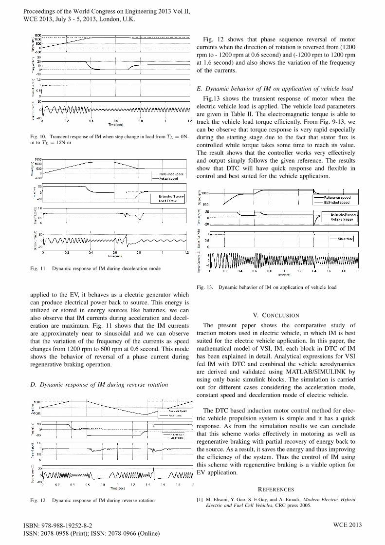
Fig. 10. Transient response of IM when step change in load from TL = 0N-m to TL = 12N-m
Fig. 11. Dynamic response of IM during deceleration mode
applied to the EV, it behaves as a electric generator whichcan produce electrical power back to source. This energy isutilized or stored in energy sources like batteries. we canalso observe that IM currents during acceleration and decel-eration are maximum. Fig. 11 shows that the IM currentsare approximately near to sinusoidal and we can observethat the variation of the frequency of the currents as speedchanges from 1200 rpm to 600 rpm at 0.6 second. This modeshows the behavior of reversal of a phase current duringregenerative braking operation.
D. Dynamic response of IM during reverse rotation
Fig. 12. Dynamic response of IM during reverse rotation
Fig. 12 shows that phase sequence reversal of motorcurrents when the direction of rotation is reversed from (1200rpm to - 1200 rpm at 0.6 second) and (-1200 rpm to 1200 rpmat 1.6 second) and also shows the variation of the frequencyof the currents.
E. Dynamic behavior of IM on application of vehicle load
Fig.13 shows the transient response of motor when theelectric vehicle load is applied. The vehicle load parametersare given in Table II. The electromagnetic torque is able totrack the vehicle load torque efficiently. From Fig. 9-13, wecan be observe that torque response is very rapid especiallyduring the starting stage due to the fact that stator flux iscontrolled while torque takes some time to reach its value.The result shows that the controller works very effectivelyand output simply follows the given reference. The resultsshow that DTC will have quick response and flexible incontrol and best suited for the vehicle application.
Fig. 13. Dynamic behavior of IM on application of vehicle load
V. CONCLUSION
The present paper shows the comparative study oftraction motors used in electric vehicle, in which IM is bestsuited for the electric vehicle application. In this paper, themathematical model of VSI, IM, each block in DTC of IMhas been explained in detail. Analytical expressions for VSIfed IM with DTC and combined the vehicle aerodynamicsare derived and validated using MATLAB/SIMULINK byusing only basic simulink blocks. The simulation is carriedout for different cases considering the acceleration mode,constant speed and deceleration mode of electric vehicle.
The DTC based induction motor control method for elec-tric vehicle propulsion system is simple and it has a quickresponse. As from the simulation results we can concludethat this scheme works effectively in motoring as well asregenerative braking with partial recovery of energy back tothe source. As a result, it saves the energy and thus improvingthe efficiency of the system. Thus the control of IM usingthis scheme with regenerative braking is a viable option forEV application.
REFERENCES
[1] M. Ehsani, Y. Gao, S. E.Gay, and A. Emadi,, Modern Electric, HybridElectric and Fuel Cell Vehicles, CRC press 2005.
Proceedings of the World Congress on Engineering 2013 Vol II, WCE 2013, July 3 - 5, 2013, London, U.K.
ISBN: 978-988-19252-8-2 ISSN: 2078-0958 (Print); ISSN: 2078-0966 (Online)
WCE 2013

[2] Mehrdad Ehsani, Khwaja M. Rahman and Hamid A. Toliyat, “Propul-sion System Design of Electric and Hybrid Vehicles,” IEEE Tran. OnIndustrial Electronics ,Vol.44, Feb 1997.
[3] M. Zeraoulia, M. E. H. Benbouzid and D. Diallo, “Electric motor driveselection issues for HEV propulsion systems: a comparative study”,IEEE Tran. on Industrial Electronics, Vol.44, No.6, pp.1756-1764,November 2006.
[4] Chang, L.; “Comparison of AC drives for electric vehicles-a report onexperts’ opinion survey”, Aerospace and Electronic Systems Magazine,IEEE , vol.9, no.8, pp.7-11, Aug. 1994.
[5] Depenbrock, M., “Direct self control for high dynamics performanceof inverter feed AC machines” ETZArchiv, Vol. 7, pp.211-218,1985.
[6] Takahashi, I. Noguchi, “A new quick response and high efficiencystrategy of an induction motor”Conf. Rec. IEEE-IAS Annual Meeting,pp.495-502, 1985.
[7] J. Faiz, M. B. B. Sharifian, Ali Keyhani, and A. B. Proca, “SensorlessDirect Torque Control of Induction Motors Used in Electric Vehicle”IEEE Trans. Energy Conversion, Vol.18, No.1, Mar 2003.
[8] J. Faiz, M. B. B. Sharifian, Ali Keyhani, and A. B. Proca,, “DirectTorque Control of Induction Motor for Electric Propulsion Systems”Electric Power Systems Research, Vol.51, pp 95-101, Aug 1999.
[9] Bhim Singh, Pradeep Jain, A.P.Mittal, Member and J.R.P.Gupta, “DirectTorque Control: A Practical Approach to Electric Vehicle” Power IndiaConference, 2006 IEEE, Vol.4, 2006.
[10] Singh, B.; Jain, P.; Mittal, A.P.; Gupta, J.R.P, “Speed sensorless electricvehicle propulsion system using DTC IM drive” Power Electronics,2006. IICPE 2006. India International Conference on vol., no., pp.7-11, 19-21 Dec. 2006.
[11] JamesLarminie, John Lowry, “Electric Vehicle Technology Ex-plained”, John Wiley and Sons Ltd.
[12] Trovao, J.P.; Pereirinha, P.G.; Jorge, H.M.;“Simulation model and roadtests comparative results of a small urban electric vehicle”IndustrialElectronics, 2009. IECON ’09. 35th Annual Conference of IEEE, pp836-841, 3-5 Nov. 2009
[13] P.C. Krause,“Analysis of electric Machinery”, McGraw-Hill Bookcompany, 1987.
[14] G. Buja, D. Casadei, and G. Serra,“Direct stator flux and torque controlof an induction motor: Theoretical analysis and experimental results”in Proc. IECON 98, 24th Ann. Conf. IEEE Ind. Electron. Soc, Vol.1,pp.50-64, 1998.
[15] Peter Vas “Sensorless Vector and Direct Torque Control”, OxfordUniversity Press 1998.
[16] Chee Mun ONG “Dynamic Simulation of Electric Machinery”, Pren-tice Hall 1998.
[17] N. R. N. Idris, A.H. M. Yatim, “Direct Torque Control of inductionMachines with constant switching frequency and Reduced TorqueRipple ” IEEE Tran. on Industrial Electronics, Vol.51, No.4, 2004.
Proceedings of the World Congress on Engineering 2013 Vol II, WCE 2013, July 3 - 5, 2013, London, U.K.
ISBN: 978-988-19252-8-2 ISSN: 2078-0958 (Print); ISSN: 2078-0966 (Online)
WCE 2013