Embed Size (px)
Citation preview

This article was downloaded by: [UQ Library]On: 05 November 2014, At: 03:27Publisher: Taylor & FrancisInforma Ltd Registered in England and Wales Registered Number: 1072954 Registered office: Mortimer House,37-41 Mortimer Street, London W1T 3JH, UK
Fuel Science and Technology InternationalPublication details, including instructions for authors and subscription information:http://www.tandfonline.com/loi/lpet19
A SINGLE-STAGE, LIQUID-PHASE DIMETHYL ETHERSYNTHESIS PROCESS FROM SYNGAS III. DUAL CATALYSTCRYSTAL GROWTH, DEACTIVATION, AND ACTIVITYCONSERVATION STUDIESMakarand R. Gogate a , Annabelle Foos a , Sunggyu Lee a & Conrad J. Kulik ba Department of Chemical Engineering , The University of Akron Akron , Ohio, 44325b Fuel Science Program , Electric Power Research Institute , Palo Alto, California, 94304Published online: 27 Apr 2007.
To cite this article: Makarand R. Gogate , Annabelle Foos , Sunggyu Lee & Conrad J. Kulik (1991) A SINGLE-STAGE, LIQUID-PHASE DIMETHYL ETHER SYNTHESIS PROCESS FROM SYNGAS III. DUAL CATALYST CRYSTAL GROWTH, DEACTIVATION, ANDACTIVITY CONSERVATION STUDIES, Fuel Science and Technology International, 9:8, 949-975, DOI: 10.1080/08843759108942306
To link to this article: http://dx.doi.org/10.1080/08843759108942306
PLEASE SCROLL DOWN FOR ARTICLE
Taylor & Francis makes every effort to ensure the accuracy of all the information (the “Content”) containedin the publications on our platform. However, Taylor & Francis, our agents, and our licensors make norepresentations or warranties whatsoever as to the accuracy, completeness, or suitability for any purpose of theContent. Any opinions and views expressed in this publication are the opinions and views of the authors, andare not the views of or endorsed by Taylor & Francis. The accuracy of the Content should not be relied upon andshould be independently verified with primary sources of information. Taylor and Francis shall not be liable forany losses, actions, claims, proceedings, demands, costs, expenses, damages, and other liabilities whatsoeveror howsoever caused arising directly or indirectly in connection with, in relation to or arising out of the use ofthe Content.
This article may be used for research, teaching, and private study purposes. Any substantial or systematicreproduction, redistribution, reselling, loan, sub-licensing, systematic supply, or distribution in anyform to anyone is expressly forbidden. Terms & Conditions of access and use can be found at http://www.tandfonline.com/page/terms-and-conditions

FUEL SCIENCE AND TECHNOLOGY INT'L., 9(8), 949-975 (1991)
A SINGLE-STAGE, LIQUID-PHASE DIMETHYL ETHER SYNTHESIS PROCESS FROM SYNGAS
111. DUAL CATALYST CRYSTAL GROWTH, DEACTIVATION, AND ACTIVITY CONSERVATION STUDIES
Makarand R. Gogate, Annabelle Foos*, Sunggyu ~ee+, and Conrad J. ~ulik#
Department of Chemical Engineering The University of Akron
Akron, Ohio 4 4 3 2 5
#Fuel Science Program Electric Power Research Institute
Palo Alto, California 94304
ABSTRACT
In the liquid phase dimethyl ether (DME) synthesis process, both the methanol synthesis catalyst (composed of CuO, ZnO, and A1203) and the methanol dehydration catalyst (composed of gamma-alumina) are slurried in the inert oil phase. Various long-term activity checks were conducted on these dual catalysts to characterize the crystal growth and the thermal aging behavior. X-ray powder diffraction, X-ray fluorescence and elemental intensity compositions, and the crystallite size distributions of the aged catalysts were examined. Based on the current investigation, it was established that the crystal growth and the catalyst deactivation problems in the methanol synthesis catalyst are less severe when it is used along with the methanol dehydration catalyst.
I
+TO whom all correspondence should be directed. *currently with the Department of Geology.
Copyright O 1991 by Marcel Dekker, Inc
Dow
nloa
ded
by [
UQ
Lib
rary
] at
03:
27 0
5 N
ovem
ber
2014
GOGATE ET AL.
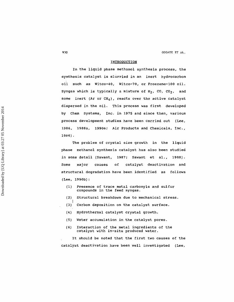
INTRODUCTION
In the liquid phase methanol synthesis process, the
synthesis catalyst is slurried in an inert hydrocarbon
oil such as Witco-40, Witco-70, or Freezene-100 oil.
Syngas which is typically a mixture of Hz, CO, C02, and
some inert (Ar or CH4), reacts over the active catalyst
dispersed in the oil. This process was first developed
by Chem Systems, Inc. in 1975 and since then, various
process development studies have been carried out (Lee,
1986, 1988a, 1990a; Air Products and Chemicals, Inc.,
1986).
The problem of crystal size growth in the liquid
phase methanol synthesis catalyst has also been studied
in some detail (Sawant, 1987; Sawant et al., 1988).
Some major causes of catalyst deactivation and
structural degradation have been identified as follows
(Lee, l99Ob) :
(1) Presence of trace metal carbonyls and sulfur compounds in the feed syngas.
(2) Structural breakdown due to mechanical stress. I
(3) Carbon deposition on the catalyst surface.
(4) Hydrothermal catalyst crystal growth.
(5) Water accumulation in the catalyst pores.
(6) Interaction of the metal ingredients of the catalyst with in-situ produced water.
It should be noted that the first two causes of the
catalyst deactivation have been well investigated (Lee,
Dow
nloa
ded
by [
UQ
Lib
rary
] at
03:
27 0
5 N
ovem
ber
2014

DIMETHYL ETHER SYNTHESIS PROCESS. 111 951
1990b), and can almost entirely be eliminated. The
presence of carbon deposition on the catalyst surface is
very difficult to envisage when the methanol synthesis
catalyst is immersed in oil, as in the liquid phase
methanol synthesis process. Further, although very much
suspected, this fact has never been corroborated with
concrete experimental evidence before. The remaining
three causes are, however, very much present in the
liquid phase methanol synthesis process, and all of
these focus on the role of water in promoting the
crystal growth and mineral leaching from the synthesis
catalyst.
In the liquid phase methanol synthesis process,
water is inevitably produced along with methanol,
although the overall selectivity towards methanol is
always kept very high by the forward water gas shift
reaction. The reactions which occur in the liquid phase
methanol synthesis process under normal CO-rich syngas
conditions are (Lee, 1990b):
When this reaction system is modified to co-produce
methanol and DME (Lee et al., 1988b, 1990~). the
reaction chemistry includes the DME synthesis reaction
via methanol dehydration and is represented by:
Dow
nloa
ded
by [
UQ
Lib
rary
] at
03:
27 0
5 N
ovem
ber
2014

GOGATE ET AL.
Thus, this system has one more source of water
generation. However, again, since the water gas shift
reaction (4) proceeds faster than the methanol synthesis
reaction (3) and the methano1,dehydration reaction .(5),
the selectivity towards methanol and DME is always
maintained very high (Lee et al., 1990~). ~x~eriments
also show that very little water is produced in net
amount.
Although the selectivity towards the products (DME
and methanol) is very high, it is generally realized
that the presence of water is very important in
modifying the reaction environment and in increasing the
rate of methanol synthesis. However, at the same time,
water can damage the catalyst by any of the causes (d)
through (f) listed above. Since the co-production of
DME and methanol has two sources of water generation,
the effect of these causes can be more critical and
significant. Thus, the crystal growth and deactivation
problems have to be extensively reexamined in this
process. The current study attempts to clarify some of
these important issues relating to catalyst life and
activity conservation.
Dow
nloa
ded
by [
UQ
Lib
rary
] at
03:
27 0
5 N
ovem
ber
2014

DIMETHYL ETHER SYNTHESIS PROCESS. I11 953
EXPERIMENTAL
A laboratory scale pilot plant was designed and
built as a part of this and other ongoing research. All
the activity measurements of niethanol and DME synthesis
were made on a one-liter, mechanically agitated slurry
reactor. The sketch of the slurry reactor system along
with all the peripheral units is given elsewhere (Lee,
1990a, 1990b) . A CO-rich syngas having compositions which simulate
closely to those of typical Texaco or Koppers-Totzek
syngas was used for this study. In particular, the
nominal composition of the syngas was H2:CO:C02:CH4 =
36:48:8.5:7.5. Commercial methanol synthesis catalyst
composed of CuO, ZnO, and A1203 and designated as EPJ-19
by the manufacturer United Catalysts, Inc., was used.
Methanol dehydration catalyst composed of pure
gamma-alumina and designated as AL-3916P by the
manufacturer Harshaw-Filter01 Partnership, Inc., was
used along with EPJ-19. The inert liquid phase employed
for this inverstigation was the Witco-40 white mineral
oil, manufactured by Witco Corporation. This inert oil
could be easily replaced by Witco-70, Witco-100, or
Freezene-100 oils.
After each long-term activity check was over, the
slurry containing the active catalyst was pumped out.
This active catalyst, when exposed to air, could be
Dow
nloa
ded
by [
UQ
Lib
rary
] at
03:
27 0
5 N
ovem
ber
2014

Dow
nloa
ded
by [
UQ
Lib
rary
] at
03:
27 0
5 N
ovem
ber
2014

DIMETHYL ETHER SYNTHESIS PROCESS. I11 955
methanol dehydration catalyst). In the co-production of
methanol and DME, these two catalysts are slurried
together in the oil. Gamma-alumina was found to be
perfectly stable at the nominal reaction conditions
employed for the dehydration of methanol to DME (Gogate,
1990). The copper-based methanol catalyst was, however,
suspected to be far more sensitive to hydrothermal
crystal growth (Sawant et al., 1988). The purpose of
this investigation was thus to study whether the crystal
growth in the copper-based methanol synthesis catalyst
is alleviated by using it along with gamma-alumina in
the liquid phase, for the co-production of methanol and
DME, i-e., to check whether gamma-alumina exhibits any
synergistic beneficial effect on the methanol synthesis
catalyst. If so, this could be a very significant
side-benefit of the co-production approach, the primary
benefit being the fact that it has been shown to improve
reactor productivities and syngas conversions by as much
as 60% (Lee et al., 1988b, 1990~).
To qualify and quantify the problems of catalyst
crystal growth, deactivation, and hydrothermal leaching,
the following techniques were used:
(1) Thermal aging of the methanol synthesis catalyst under both continuous and batch reaction conditions, for methanol synthesis and dual catalysis (Co-production of methanol and DME).
(2) X-ray diffraction patterns for the aged catalysts.
Dow
nloa
ded
by [
UQ
Lib
rary
] at
03:
27 0
5 N
ovem
ber
2014

GOGATE ET AL. '
(3) X-ray fluorescence patterns and elemental intensities of the aged catalysts and process oils.
(4) Crystallite size distributions of the aged catalysts by the Fourier Line Profile Analysis.
(5) Average crystallite size determination.
The experimental scheme employed for this study has
been summarized in Table I. Three experiments were
conducted in a batch mode and two in a continuous mode.
The average crystal size of the freshly reduced catalyst
was 3.9 nm. The crystallite size distribution of this
catalyst is shown in Figure 1. The crystallite size
distribution has two distinct peaks, at 3 nm and at 7
nm; respectively. All the copper crystallites are in
the size range of 2-4 nm and 6-8 nm. There are
absolutely no crystallites in the 10-14 nm size range.
Crystallites in the size range 2-4 nm have a weight
function intensity of 0.5.
The crystallite size distributions of the aged
catalysts in a batch mode are shown in Figures 2-4. The
nominal compositions of the normal syngas, the CO-free
syngas, and the COZ-free syngas under which the
catalysts were aged are given in Table I. The average
crystal sizes of these three aged catalysts is 4.4 nm,
5.0 nm, and 4.6 nm, respectively. The average crystal
size is thus significantly greater than that for the
freshly reduced catalyst. Crystallites in the size
Dow
nloa
ded
by [
UQ
Lib
rary
] at
03:
27 0
5 N
ovem
ber
2014

DIMETHYL ETHER SYNTHESIS PROCESS. 111
Table I
Summary of Crystal Size Growth Experiments for Dual Catalysts
Sample EDME14 EDME18 EDME19 EDME15 EDME16 EDME17 ........................................................ Mode of Operation R C C B B B ........................................................ Temp. (OK) 523 523 523 523 523 ........................................................ Pres. (MPa) 0.345 5.585 5.688 5.792 5.722 5.722 ........................................................ Feed Gas Composition Mole % ........................................................ Hz 5.0 59.3 33.6 37.4 59.3 33.6 N2 95.0 0.0 0.0 0.0 0.0 0.0 CO 0.0 0.0 55.4 46.3 0.0 55.4 co2 0.0 35.4 0.0 7.7 5.3 0.0 CH4 0.0 5.3 11.4 8.6 35.4 11.4 ........................................................ Time (Hours) 60 6 0 64 5 5 6 6 ........................................................ Crystal Size (nm) 3.9 5.2 5.5 4.4 5.0 4.6
Notes: 15 g MeOH Synthesis Catalyst and 1 g Gamma-Alumina was used as dual catalyst. 550 ml of Witco-40 oil was added to make the slurry. Continuous operating mode is indicated by C, and the batch operating mode is indicated by B. R indicates catalyst reduction.
range of 10-14 nm are present in all these aged
catalysts. At the same time, the weight function of the
crystallites in the size range of 2-4 nm is decreased
accompanied by a simultaneous increase in the weight
function of the crystallites in the size range of 6-8
and 10-ld nm
Dow
nloa
ded
by [
UQ
Lib
rary
] at
03:
27 0
5 N
ovem
ber
2014

Average Crystal Size = 3 . 9 nm
0 2 4 6 8 10 12 14 16
Cryetallite Sire (nm)
Figure 1 . C r y s t a l l i t e S i z e Dis tr ibut ion of Freshly Reduced Dual Cata lys t .
Figure 2 . C r y s t a l l i t e S i z e ~ i s t r i b u t i o n of An Aged Catalyst i n Normal Syngas f o r 64 Hours i n a Batch Mode.
16
0.5
0.4 -
c 0 .- .4
0.3 - c I: u .r .- ff 0.2 -
0.1 -
0 ,
Average Crystal S i z e = 4 . 4 nm
0 0
0
0 O
0 0 0
0 D 0
, C, n -
I I I I I 3 I I I I I - I = 0 2 4 6 8 10 12 14
Dow
nloa
ded
by [
UQ
Lib
rary
] at
03:
27 0
5 N
ovem
ber
2014

0'5 r- Average Crystal Size = 5 . 0 nt
0 2 4 6 8 10 12 14
Ctystollite Size (nm)
Figure 3 . C r y s t a l l i t e S i z e Dis tr ibut ion of An Aged Cata lys t i n No-CO Syngas f o r 5 5 Hours i n a Batch Mode.
I Average Crystal S i z e = 4 . 6 nm
Crystallite Size (nm)
Figure 4 . C r y s t a l l i t e S i z e Dis tr ibut ion o f An Aged Catalyst i n No-C02 Syngas f o r 66 Hours i n a Batch Mode.
Dow
nloa
ded
by [
UQ
Lib
rary
] at
03:
27 0
5 N
ovem
ber
2014

960 GOCATE ET AL.
The crystallite size distributions of the aged
catalysts in a continuous mode are shown in Figures 5
and 6. The catalyst in Figure 5 was aged for 60 hours
in the C02-free syngas having a nominal" composition of
H2:CO:CH4 = 33.6:55.3:11.1. The average crystal size of
this catalyst was 5.4 nm. The crystallite size
distribution of this catalyst falls in two distinct size
ranges of 2-6 and 8-12 nm. The catalyst in Figure 6 was
aged for 60 hours in the CO-free syngas having a nominal
composition of H2:C02:CH4 = 59.2:35.5:5.3. The average
crystallite size was 5.2 nm. The crystallite size
distribution of this catalyst was nearly trimodal in the
sense that it had three distinct peaks in the size
ranges of 2-6, 6-10, and 12-14 nm.
It was very apparent that the copper catalyst
crystals had undergone a pronounced increase in the
crystal size over only 60 hours of use, under both the
CO-free and the C02-free environment. The crystallite
size distribution also had underwent a very significant
shift in the sense that the crystals in the lower range
Of sizes (2-6 nm) had now a lower weight function and
those in the higher range (6-10 nm) were of much higher
weight function. Crystals in the size range of 10-14 nm
also appear for the first time in the aged catalysts.
To explain this shift in the crystallite size
distributions, the atomic migration model has been
applied before (Lee, 1989).
Dow
nloa
ded
by [
UQ
Lib
rary
] at
03:
27 0
5 N
ovem
ber
2014

Crystollite Size (nm)
0.4 -
C 0 0.3 - - " C
I: - L D - 0.2 - :
0.1 -
0
Figure 5. Crystallite Size Distribution of An Aged Catalyst in No-C02 Syngas for 70 Hours in a Continuous Mode.
Average Crystal S i z e = 5 . 4 nm
0 0
0
0 D
0 D
0 0
0 0 - D 0 " - I -4 I I I I I I I I I I -
0.50
Average Crystal S i z e = 5 . 2 nm
Crystollite Size (nm)
Figure 6. Crystallite Size Distribution of an Aged Catalyst in a No-CO Syngas for 60 Hours in a Continuous Mode.
Dow
nloa
ded
by [
UQ
Lib
rary
] at
03:
27 0
5 N
ovem
ber
2014

GOGATE ET AL.
Table I1
Summary of Crystal Size Growth Experiments for Methanol synthesis'
Sample EPJ 905 903 904 908 910 911 ........................................................ Mode of Operation R C C B B B
Temp. (OK) 523 523 523 523 523 ........................................................ Pres. (MPa) 6.998 6.998 5.516 5.516 5.516 5.516 ........................................................ Feed Gas Composition Mole %
H2 5.0 59.3 33.6 36.0 36.0 36.0
N2 95.0 0.0 0.0 0.0 0.0 0.0 CO 0.0 0.0 55.4 48.0 48.0 48.0
co2 0.0 35.4 0.0 7.6 7.6 7.6
CH4 0.0 5.3 11.4 8.4 8.4 8.4 ........................................................ Time (Hours) 60 6 0 100 75 5 0 ........................................................ Crystal size (nm) 2.9 10.5 8.0 4.4 4.3 4.6
(+: Sawant et al., 1988)
The crystal size growth data for the methanol
synthesis catalyst, aged under conditions of purely
methanol synthesis, have been presented in Table 11.
his and the experimental scheme in Table I were carried out under very similar reactor operating conditions.
Comparing the average crystal size for these two cases,
dual catalysts are shown to offer a very favorable
scenario for the crystal size growth and catalyst
Dow
nloa
ded
by [
UQ
Lib
rary
] at
03:
27 0
5 N
ovem
ber
2014

DIMETHYL ETHER SYNTHESIS PROCESS. I11
Table I11
Dual Catalyst Activity in Normal Syngas, No-CO Syngas and No-C02 Syngas
Operating Conditions: Catalyst 15 g of EPJ-19
I g of Gamma-Alumina Temperature 250°C Pressure 5.792 MPa Oil 550 ml of Witco-40 oil Impeller speed : 1500 rpm Feed flow rate : 1 SLPM
Syngas Type ~ormal# No-CO NO-C02 ........................................................ Reactor Feed Flow Rate and Mole Fractions
Flow, mol/h 2.6786 2.6787 2.6787
Hydrogen 0.3616 0.5920 0.3307 CO 0.4836 0.0000 0.5556 Methane 0.0790 0.0530 0.1137 Carbon dioxide 0.0757 0.3550 0.0000 ........................................................ Reactor Exit Flow Rate and Mole Fractions
Flow, mol/h 1.9557 2.5496 2.0681
Hydrogen 0.1956 0.5329 0.1949 CO 0.4469 0.0261 0.5232 Methane 0.1082 0.0557 0.1439 Carbon dioxide 0.1425 0.3257 0.0585 Water 0.0012 0.0408 0.0005 Methanol 0.0755 0.0189 0.0343 DME 0.0300 0.0000 0.0485 ....................................................... Reaction Rates (mol/kg cat (MeOH). h)
Hydrogen -39.0705 -15.1313 -33.1707 CO -28.0853 +4.4331 -26.5433 Carbon dioxide +5.0546 -8.0387 +8.0678 Water +O. 1560 +6.9281 +O. 0690 Methanol +9.8473 +3.2109 +4.1972 ....................................................... Reaction Rate (mol/kg cat (DME). h)
DME +58.6191 0.0000 +100.2266
Note: # : The data for normal syngas is at 7.0 MPa.
Dow
nloa
ded
by [
UQ
Lib
rary
] at
03:
27 0
5 N
ovem
ber
2014

964 GOGATE ET AL.
Figure 7. X-ray Diffraction Pattern of an Unreduced Methanol Synthesis Catalyst.
deactivation. This simply means that methanol synthesis
catalyst could conserve its original activity longer,
when aged along with the methanol dehydration catalyst.
This bears a very important implication: not only
higher productivities were obtained in the co-production
of methanol and DME, these productivities could be
maintained much longer than those for methanol synthesis
alone.
Dow
nloa
ded
by [
UQ
Lib
rary
] at
03:
27 0
5 N
ovem
ber
2014

DIMETHYL ETHER SYNTHESIS PROCESS. I11 965
Figure 8. X-ray D i f f r a c t i o n P a t t e r n o f Freshly Reduced Dual C a t a l y s t .
To assess the influence of reaction environment on
the average crystal size and the crystallite size
distribution, the reaction rate data from the CO-free
and the C02-free syngas case are given in Table 111. For
the CO-free syngas case, the selectivity to methanol was
only 32%. The selectivity to water was unusually high
at 68%. Absolutely no DME was formed for this case. For
the C02-free syngas case, however, the selectivity to
Dow
nloa
ded
by [
UQ
Lib
rary
] at
03:
27 0
5 N
ovem
ber
2014

COGATE ET AL.
F igu re 9. X-ray D i f f r a c t i o n P a t t e r n o f Dual Ca ta l ys t Aged i n Normal Syngas f o r 64 hours i n a Batch Mode.
methanol was almost 99.9%. Both DME and C02 had
significant positive synthesis rates. Thus, the
reaction environment in CO-free syngas case was
water-rich, whereas that in the C02-free syngas case was
methanol and CO-rich. The average crystal size for the
C02-free syngas case was 5.4 nm, whereas that for the
CO-free syngas case was 5.2 nm. This insignificant
difference in the crystal size of these two cases night
have been due to insufficient aging time (60 hours).
Dow
nloa
ded
by [
UQ
Lib
rary
] at
03:
27 0
5 N
ovem
ber
2014

DIMETHYL ETHER SYNTHESIS PROCESS. 111
Figure 10. X-ray Diffraction Pattern of Dual Catalyst Aged in No-CO Syngas for 55 hours i n a Batch Mode.
The X-ray diffraction patterns for the aged
catalysts are given in Figures 7-15. It is shown that
all the copper peaks in the aged catalysts have become
sharper and have more intensity when compared to that
for the freshly reduced catalyst. The best graphic
comparison is illustrated in Figures 13 and 15. In
Figure 13, the X-ray diffraction peak for the Cu(ll1) is
Dow
nloa
ded
by [
UQ
Lib
rary
] at
03:
27 0
5 N
ovem
ber
2014

GOGATE ET AL.
Figure 1 1 . X-ray Diffraction Pattern of Dual Catalyst Aged in NO-C02 Syngas for 66 hours in a Batch Mode.
compared among the freshly reduced catalyst, the
catalyst aged in the C02-Tree syngas for 60 hours in a 1
batch mode, and the catalyst aged in the COZ-free syngas 1
for 60 hours in a continuous mode. In Figure 15, a
similar comparison is made for the CO-free syngas case.
It is shown that when compared to that of the freshly
reduced catalyst, the Cu(ll1) peaks for the catalyst
aged in both batch and continuous mode are sharper and
Dow
nloa
ded
by [
UQ
Lib
rary
] at
03:
27 0
5 N
ovem
ber
2014

DIMETHYL ETHER SYNTHESIS PROCESS. I11
Figure 12. X-ray Diffraction Pattern of Dual Catalyst Aged i n No-LO2 Syngas for 60 hours in Continuous Mode.
have a much higher intensity. At the same time, the
catalyst aged in a continuous mode has a higher
intensity than that for the batch mode. This is
indicative of the fact that the thermal aging problems
are more severe in the continuous mode than in the batch
mode. This might be due to the fact that in the batch
mode, the synthesis reactions come to equilibrium very
quickly as opposed to that for the continuous mode. A
Dow
nloa
ded
by [
UQ
Lib
rary
] at
03:
27 0
5 N
ovem
ber
2014

GOGATE ET AL.
F i g u r e 13. Comparative X-ray D i f f r a c t i o n P a t t e r n s f o r Cu (111) Peak For F r e s h l y Reduced. Aged f o r 60 hours i n Batch Mode, and Aged f o r 60 hours i n Continuous Yode, i n No-COZ Syngas.
x103
similar fact is ,borne out by the average crystal size
comparison for' these cases.
The X-ray fluorescence (XRF) patterns for the fresh
and aged catalysts as well as the used process oils have
been given in Figures 16-18. The most interesting
2.00 -
1.80 '
1 .i.0
1.40 '
l.20 .
observat'ion was that in the used process oils, trace
amounts of copper and zinc were detected. The elemental
- '
No-C02 Syngas, 60 Hours, C
n
Dow
nloa
ded
by [
UQ
Lib
rary
] at
03:
27 0
5 N
ovem
ber
2014

DIMETHYL ETHER SYNTHESIS PROCESS. I11 971
Figure 14. X-ray D i f f r a c t i o n P a t t e r n o f Dual C a t a l y s t Aged i n No-CO Syngas f o r 60 Hours i n Continuous Mode.
intensities for these in Witco-40 oil are, however, very
small when compared to that for either aged or freshly
reduced catalysts. The hydrothermal leaching problems
are thus almost negligible, over the aging periods
considered in this study. However, by ' looking at the
trend in the values for the copper intensities, the
copper intensity in used Witco-40 oil was the most under
the CO-free syngas case. This case was also an
Dow
nloa
ded
by [
UQ
Lib
rary
] at
03:
27 0
5 N
ovem
ber
2014

1 .80
1.60
No-CO Syngas. 60 Hours. C 1.40 No-CO Syngas. 55 Hours, B
1.20
1 .OO
0 . m
0.60
G .40
0.28
F igu re 15. Comparative X-ray D i f f r a c t i o n Pat te rns f o r Cu (111) Peak f o r F resh l y Reduced Ca ta l ys t , Aged i n 60 Hours i n Continuous Mode. and Aged i n 55 Hours i n Batch Mode, i n No-CO Syngas.
F igu re 16. X-ray Fluoroscence P a t t e r n and Elemental I n t e n s i t i e s f o r a Fresh ly Reduced Dual Cata lys t .
Dow
nloa
ded
by [
UQ
Lib
rary
] at
03:
27 0
5 N
ovem
ber
2014

DIMETHYL ETHER SYNTHESIS PROCESS. I11
CuKu
1 S1K.x i 5 C N T 10.m , 20.00 , . -, . , 3@.@0 , I , ,
I 9 . E 4 K E V 10eV/ch A E D R X
I u A E D R X
I
Figure 17. X-ray Fluorescence Pattern and Elemental Intensities for an Aged Catalyst in No-C02 Syngas for 70 Hours in a Continuous Mode.
water-rich environment, since the catalyst selectivity
to water was 68%. Thus, water-rich environment in the
methanol-DME synthesis is suspected to be detrimental in
both ways, viz., it promotes the structural degradation
of the catalyst by hydrothermal leaching, and second, it
promotes the crystallite size growth of the copper
crystallites, as evidenced by the crystal growth data.
CONCLUSIONS
The crystal size growth in the methanol synthesis
catalyst when aged in presence of the methanol
dehydration catalyst was investigated for the first
Dow
nloa
ded
by [
UQ
Lib
rary
] at
03:
27 0
5 N
ovem
ber
2014

COGATE ET AL.
Figure 18 . X-ray Fluoroscence Pattern and Elemental Intensities o f Copper and Zinc i n Witco-40 Oil f o r an Aged Catalyst under no-CO Syngas f o r 60 Hours i n a Continuous Mode.
time. Water and methanol-rich liquid phase were found
to promote catalyst crystal growth. The crystal growth
problems in the copper-based methanol catalysts when
used in the dual catalyst mode were found to be far less
severe than when the catalysts were used for methanol
synthesis alone. Thus, the co-production of methanol
and DME renders yet another advantage in the catalyst
activity maintenance.
ACKNOWLEDGEMENTS
This work was fully sponsored by the Electric Power
Redearch Institute through its research contract
RP317-6. The authors are greatly indebted to Howard, E.
Lebowitz of the Electric Power Research lnstitutelfor
his continued support and encouragement.
Dow
nloa
ded
by [
UQ
Lib
rary
] at
03:
27 0
5 N
ovem
ber
2014

DIMETHYL ETHER SYNTHESIS PROCESS. 111
REFERENCES
Air Products and Chemicals, Inc.. 1986. Liquid-Phase Methanol Process Development Unit (PDU) - 40 Day Run at LaPorte, Texas, Final Report AP-4430, Electric Power Research Institute, Palo Alto, California.
Gogate, M. R.. 1990. Kinetics of Methanol Dehydration to Dimethyl Ether. M. S. Thesis, The University of Akron.
Lee, B. G.. 1989. Regeneration and Post-Treatment of Industrial Co-precipated Methanol Synthesis Catalyst. Ph. D. Dissertation, The University of Akron.
Lee, S.. 1986. Research to Support Development of Liquid Phase Methanol Synthesis Process. Interim Report AP-4429, Electric Power Research Institute, Palo Alto, California.
Lee, S.. 1988a. Mass transfer in the Liquid Phase Methanol Synthesis ( L P M ~ O H ~ ~ ) Process. Interim Report EPRI AP-5758. Electric Power Research Institute, Palo Alto, California.
Lee, S., Parameswaran, V. R., Lee, B. G., and Gogate, M. R.. 1988b. Novel Developments and Enhancements in Methanol Synthesis. Proc. of Indirect Liquefaction Contractors' Review Meeting (USDOE/PETC), Pittsburgh, Pennsylvania, November 15-17.
Lee, S.. 1990a. Reaction Mechanisms in Liquid Phase Methanol Synthesis, Interim Report ER/GS-6715, Electric Power Research Institute, Palo Alto, California.
Lee, S.. 1990b. Methanol Synthesis Technology, CRC Press, Boca Raton, Florida, 1990.
Lee, S., Gogate, M. R., and P. Vijayaraghavan. 1990c. Development of Single-Stage, Liquid-Phase synthesis Process of Dimethyl Ether from CO-rich Syngas. Invited Paper Presented at the 15th Annual EPRI Contractors' Conference on Fuel Science and Conversion, Electric Power Research Institute, Palo Alto, California.
Sawant, A. V.. 1987. The Effect of Thermal Aging, Water, and C02 on the Liquid Phase Methanol Synthesis Catalyst. Ph.D. Dissertation, The University of Akron.
Sawant, A. V., Lee, S., and Foos, A.. 1988. Crystal Size Growth in the Liquid Phase Methanol Synthesis Catalyst. Fuel Sci. and Tech. Inttl, 6(5), 569-589.
RECEIVED: September 24, 1990 ACCEPTED: October 15 , 1990
Dow
nloa
ded
by [
UQ
Lib
rary
] at
03:
27 0
5 N
ovem
ber
2014