Embed Size (px)
Citation preview

Journal of KONES Powertrain and Transport, Vol. 23, No. 1 2016
A SIMULATION ANALYSIS OF BEHAVIOUR OF SHIP-BORNE HELICOPTER MAIN ROTOR DUE TO SHIP MOTION
Jarosław Stanisławski
Institute of Aviation Krakowska Avenue 110/114, 02-256 Warsaw, Poland
tel.: +48 228460011, ext. 362 e-mail: [email protected]
Abstract
The paper presents a simulation method of analysis of the couplings between rotor blades motion and helicopter fuselage standing on ship deck at the phase of take-off or landing when whirling rotor generates thrust less than weight of the helicopter. The oscillating motion of the ship deck due to waves is considered. The physical model includes the helicopter fuselage treated as the stiff body supported by units of springs and dampers corresponding to landing gear characteristics. The rotor blades are modelled by elastic axes with distributed lumped masses of blade segments. The equations of fuselage and rotor blades motion are solved applying Runge-Kutta method. According to the Galerkin method, parameters of rotor blades motion are assumed as a resultant combination of considered blade torsion and bending eigen modes. Data of the light helicopter with three-bladed rotor are applied for the simulation of the rotorcraft behaviour aboard the ship. The calculations concerning helicopter standing on the fixed plane and on oscillating ship deck show influence of ship movement on fuselage motion and rotor blades deflections, flapping, and lead-lag motion. Moreover, simulations show influence of the side wind and control of the rotor swash-plate deflections. The additional unit of blade eigen modes and frequencies is applied to model the blade hitting to the flapping limiter, which can occur at the low rotation speed of the rotor. Temporary contact of the articulated blade with limiter changes its boundary conditions, which can rapidly increase the blade bending moments. The simulation method enables to determine conditions of safe operations of ship-borne helicopters without exceeding the limits and generating the excessive blade loads.
Keywords: helicopter, rotor blade, ship deck operation
1. Introduction
The safety of helicopter operations is considered the most important factor taken into account during designing and usage of rotorcraft. Helicopter offshore operations including shipboard take-off and landing create a potentially higher level of dangerous circumstances in comparison to helicopter tasks over land. Small area of ship decks, different layout of ship obstacles, variable weather conditions, motion of a flight deck due to sea state increase risk of shipboard helicopter operation. Prepared by the Civil Aviation Authority (UK) review [1] identifies problems of offshore helicopter transport in the North Sea area and analyses the helicopter accidents during period 1976 to 2013. Collected experiences of helicopter offshore flights were published in the US Coast Guard manual [5], which gathers information for safe operation procedures of shipboard helicopters. For deck operations the limitations of ship roll are defined according to type of helicopter, size of ship and the special helicopter deck lock tie-down system. The rules of proper helicopter usage on shipboard can be found in NATO publication on helicopter ship qualification tests [3] which points out the deck dangerous situations like: blade sailing, strong tail wind or wind area of inadequate helicopter yaw control. To limit the dangerous flight tests of helicopter at ship deck conditions the Flight Research Laboratory (part of the Canadian National Research Council) developed a special system [2] to emulate the positional variations of a moving ship deck in the lateral and vertical axes. For training helicopter crews in operations at shipboard environment a computational model of the Virtual Flight Deck was developed [4] including helicopter simulation, experimental ship motion data, weather data and human command. In Dutch program
ISSN: 1231-4005 e-ISSN: 2354-0133 DOI: 10.5604/12314005.1213512

J. Stanisławski
for improvements safety of helicopter operation on board offshore vessels [6] the strict operation regime was defined. For small ships, helicopters are allowed to land and stay on deck if roll and pitch angles are less than 2°.
A simulation method can be applied for research the influence of ship deck motion on behaviour of helicopter main rotor and deflections of blades. The earlier version of the computer program used for calculation of rotor loads was modified. The dynamic effects related to motion of ship deck and relative motion of helicopter fuselage due to deformations of landing gear were introduced to the equations of motion of elastic rotor blades. For slow rotating rotor, as result of decreased centrifugal forces, there may occur a phenomenon of blade hit to flap limiter at rotor hub. In the case of blade contact with the hub limiter, to model a change of blade boundary conditions, the corresponding block data of blade eigen modes and frequencies are introduced. For data of light helicopter staying on ship deck, the simulating calculations were performed applying the new version of computer program. The following two situations were consider, the case for nominal rotor speed with rotor thrust equal 40% of helicopter weight and the case of blade hit to flap limiter at reduced rotor speed to 30% of nominal value. 2. Model of helicopter
Preparing the model for simulation, it is assumed, that fuselage of helicopter standing on ship
deck can be treated as stiff body with possibility of linear and angular motion. The ship deck moves due to sea waves and flexibility of landing gear causes an additional motion of helicopter fuselage. The changes of the main rotor speed, swash-plate deflections and wind blows influence helicopter fuselage motion during take-off or landing. The rotating vector of forces at the main rotor hub can generate motion of helicopter fuselage on elastic landing gear. Applying coordination systems connected to ship mass centre, helicopter fuselage mass centre, rotor hub and rotating blades (Fig. 1) the equations of motion of the fuselage and elastic rotor blades can be formulated.
non-rotating axis
fr
hr
Ω
Of
sω
sr
Ys
Ygs
Xs Xgs
Zs
Zgs Ygn
Xgn
Zgn
Ogn
blr
Os
Oh
fω
mi
ψ
Fig. 1. Coordination systems defining localization of ship centre mass, fuselage of helicopter centre mass, main rotor
hub and mass of rotor blade segment
The forces fF and moments fM acting on the fuselage of helicopter include gravity force and reactions of other units of helicopter:
TRMRLGf FFGTF +++= , (1)
314
A Simulation Analysis of Behaviour of Ship-Borne Helicopter Main Rotor Due to Ship Motion
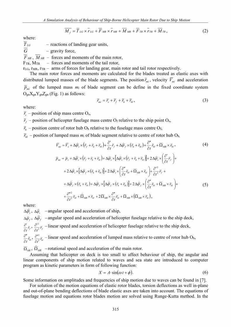
TRTRTRMRMRMRLGLGf MrFMrFrTM +×++×+×= , (2) where:
LGT – reactions of landing gear units, G – gravity force,
MRF , MRM – forces and moments of the main rotor, FTR, MTR – forces and moments of the tail rotor, rLG, rMR, rTR – arms of forces for landing gear, main rotor and tail rotor respectively.
The main rotor forces and moments are calculated for the blades treated as elastic axes with distributed lumped masses of the blade segments. The position mir , velocity miV and acceleration
mip of the lumped mass mi of blade segment can be define in the fixed coordinate system OgnXgnYgnZgn (Fig. 1) as follows:
blhfsmi rrrrr +++= , (3) where:
sr – position of ship mass centre Os,
fr – position of helicopter fuselage mass centre Of relative to the ship point Os,
hr – position centre of rotor hub Oh relative to the fuselage mass centre Of,
blr – position of lumped mass mi of blade segment relative to centre of rotor hub Oh,
( ) ( ) blMRblblhffblhfssmi rrt
rrrt
rrrVV ×Ω+∂∂ ′′
++×∆+∂∂′
+++×∆+= ϕϕ , (4)
( ) ( )[ ]
( )[ ]
( ) ( )[ ]
( )blMRMRblMRblMRbl
blMRblfblhffblhf
fblMRblsblhfs
fsblhfssblhfssmi
rrt
rrt
rrt
rrrr
rt
rrt
rr
rt
rrrrrrpp
×Ω×Ω+∂∂ ′′
×Ω+×Ω+∂∂ ′′
+
+
×Ω+
∂∂ ′′
×∆++×∆×∆++×∆+
+∂∂′
+
×Ω+
∂∂ ′′
×∆++×∆×∆+
+
∂∂′
×∆+++×∆×∆+++×∆+=
2
2
22
2
2
2
2
2
ϕϕϕϕ
ϕϕϕ
ϕϕϕϕ
,
(5)
where: sϕ∆ , sϕ∆ – angular speed and acceleration of ship,
fϕ∆ , fϕ∆ – angular speed and acceleration of helicopter fuselage relative to the ship deck,
frt∂∂′ ,
frt2
2
∂∂′ – linear speed and acceleration of helicopter fuselage relative to the ship deck,
blrt∂∂ ′′ ,
blrt2
2
∂∂ ′′ – linear speed and acceleration of lumped mass relative to centre of rotor hub Oh,
MRΩ , MRΩ – rotational speed and acceleration of the main rotor. Assuming that helicopter on deck is too small to affect behaviour of ship, the angular and
linear components of ship motion related to waves and sea state are introduced to computer program as kinetic parameters in form of following function:
( )φω +⋅= tAX sin . (6)
Some information on amplitudes and frequencies of ship motion due to waves can be found in [7]. For solution of the motion equations of elastic rotor blades, torsion deflections as well in-plane
and out-of-plane bending deflections of blade elastic axes are taken into account. The equations of fuselage motion and equations rotor blades motion are solved using Runge-Kutta method. In the
315

J. Stanisławski
case of blades according to the Galerkin method, the motion parameters are assumed as a combination of shares of the considered eigen modes of the rotor blades. The deflections of the blade elastic axis y, z, ϕ are equal to superposition of modal components:
)()(),( 1
1
111 xyttxy i
I
ii∑
=
= ρ ; z x t t z xi ii
I( , ) ( ) ( )= ∑
=δ 2 2
2 1
2; ϕ η ϕ( , ) ( ) ( )x t t xi i
i
I= ∑
=3 3
3 1
3, (7)
where: yi1, zi2, ϕi3 – eigen modes of in-plane , out-of-plane bending and torsion respectively, ρi1, δi2, ηi3 – time dependent shares of eigen modes, which are determined in computing process, I1, I2, I3 – numbers of considered bending and torsion eigen modes.
Applying dependences (7), the equations of blade motion can be converted into sets of equations (8a, 8b, 8c) related to each considered blade eigen mode:
1
2111 iYiii Qp =+ ρρ i1 = 1, ..., I1, (8a)
2
2222 iZiii Qf =+δδ i2 = 1, ...,I2, (8b)
3
2333 i
Qiii ϕνηη =+ i3 = 1, ...,I3, (8c) where: pi1
2 , fi22 , νi3
2 – square of eigen mode frequencies for bending in-plane, out-of-plane and torsion, Q Q QY Zi i i1 2 3
, , ϕ – generalized forces for considered eigen modes of the rotor blade. Aerodynamic forces acting on segment of blade at given azimuth position on the rotor disk are
computed applying the blade element theory. The local angle of attack at blade cross-section depends on control of pitch angle and on temporary conditions of airflow:
−−∆++++=
X
ZgMRyMRxo u
utgarctt κβϕϕωϕωϕϕα sincos , (9)
where: oϕ , – blade collective control angle,
φg – geometric twist, Δφ – torsion deformation, κ – coefficient of coupling flap and blade pitch, β – blade flap angle at horizontal hinge of rotor head, uz, ux – components of the cross-section airflow of rotor blade: out-of-plane and in-plane,
xϕ , yϕ – cyclic control angle due to roll and pitch deflections of the swash-plate. 3. Results of simulation
The simulations of helicopter behaviour on ship deck were performed for periods equal to 100
revolutions of the main rotor. Data of the three-bladed light helicopter were applied for calculations. The two cases of rotor speed were considered: the nominal speed equals 50.67 rad/s and rotational speed reduced to 30% of the nominal value. For both cases, the calculations were executed under following scheme. The solution of the first 10 rotor revolutions is assumed for the decay of initial conditions at fixed position of the rotor shaft. At the 10th revolution, the helicopter motion on flexible landing gear units is allowed. After the next 10 rotor revolutions, an option of ship motion is introduced.
Shown in Fig. 2a the time run of rotor thrust was obtained for the case of helicopter staying on immovable deck in windless conditions and with swash-plate in perpendicular position relative to the rotor shaft. The collective blade pitch is set to generate thrust equal to 40% of helicopter weight. Changes of rotor thrust for the same conditions, but with applied ship motion (roll oscillations as follows: φx_ship=4.4o
*sin(0.706*t)) are presented in Fig. 2b. Motion of ship deck
316

A Simulation Analysis of Behaviour of Ship-Borne Helicopter Main Rotor Due to Ship Motion
causes additional roll of helicopter fuselage on deformable landing gear units (Fig. 3b). The ship motion and blowing wind change the local attack angles of blade cross-sections at different azimuth positions, which results in higher fluctuations of rotor thrust (Fig. 3a) in comparison to windless condition.
Fig. 2. Rotor thrust for helicopter standing on ship deck at windless condition, a) immovable ship deck, b) rolling oscillations of ship deck
Fig. 3. Influence of wind on helicopter standing on ship deck, a) rotor thrust, b) ship roll and helicopter roll angle related to ship deck
The influence of wind can be noticed comparing in Fig. 4a and 4b changes of blade flap angles. In the case of no wind conditions, oscillations of blade flap angle nearly vanish for rotor revolution when temporary roll velocity of ship decreases to low value (Fig. 4a). The side wind of 9 m/s speed gives about twofold increase of blade flap oscillations (Fig. 4b). The blade flap angle varies with changes of rotor speed and with deflections of swash-plate. The range of blade flap angle increases for rotor speed reduced to 30% of nominal value. Additional increase of blade flap angle can be generated by the side wind conditions and swash-plate deflections. For some rotor revolutions (Fig. 5), a blade falling down hits the rotor hub limiter of blade flap angle, which can be noticed as horizontal parts of flap angle time run (Fig. 5b).
317

J. Stanisławski
Fig. 4. Influence of wind on flap angle of rotor blade of helicopter standing on rolling ship deck, a) no side wind Vw= 0 m/s, b) left side wind Vw= 9 m/s
Fig. 5. Blade flap angle for helicopter standing on rolling ship deck at condition of left side wind Vw=9 m/s, rotation speed of rotor reduced to 30% of nominal value, swash-plate deflected to azimuth of 90°, a) solution for 100 rotor revolutions, b) fragment of solution from 25th to 30th rotor revolution
The blade hit and following contact with flap limiter change the boundary conditions of blade connection with rotor hub. Blade contact with flap limiter influences the rotor disk distributions of blade deflections (Fig. 6, Fig. 7). During the 28th rotor revolution for the azimuth blade positions between 45° and 135°, the blade torsion deflection changes rapidly as reaction on blade hit to flap limiter (Fig. 6a). Simultaneously the out-of-plane blade deflection reaches the level of -0.6 m beneath the position of rotor rotation plane. The possibility of the lower blade tip path should be considered by ship deck personnel. The effects of blade hit to flap limiter also include high increase of out-of-plane bending moment at blade root. In Fig. 8a is presented the distribution of out-of-plane bending moment on rotor disk showing area located near blade root, where moments of high value appear. For selected azimuth positions of blade, the moment distributions along blade radius are shown in Fig. 8b. The requirement of avoidance the rapid increase the blade loads may reduce the envelope of allowed weather conditions for helicopter operations on ship deck.
318

A Simulation Analysis of Behaviour of Ship-Borne Helicopter Main Rotor Due to Ship Motion
Fig. 6. Rotor disk distribution of blade deflections during the 28th rotor revolution (see Fig. 5) in the case of blade hit to flap limiter, a) torsion blade deflection, b)out-of-plane bending deflection
Fig. 7. Rotor disk distribution of blade deflections during the 39th rotor revolution (see Fig. 5) without blade hit to flap limiter, a) torsion blade deflection, b) out-of-plane bending deflection
Fig. 8. Changes of out-of-plane blade bending moment due to blade contact with flap limiter, results for the 28th rotor revolution (see Fig. 5), a) rotor disk distribution, b) moment along blade radius for selected azimuth positions
319

J. Stanisławski
4. Conclusions
The simulation program enables an analysis of helicopter rotor behaviour due to ship motion.The limits for helicopter operations on ship deck can be defined considering the combined influence of wind condition, ship motion and range of rotor blades pitch control. The results of simulation may help to determine conditions generating potentially dangerous situations during the helicopter operation on ship deck.
References
[1] Civil Aviation Authority, Safety review of offshore public transport helicopter operations in support of the exploitation of oil and gas, CAP 1145, 2014.
[2] Mitchell, D. G., Nicoll, T. K., Fallon, M. P., Roark, S. H., Rotorcraft Handling Qualities for Shipboard Operations, AIAA Atmospheric Flight Mechanics Conference, Chicago 2009.
[3] NATO Research and Technology Organization, Helicopter/Ship Qualification Testing, RTO-AG-300, Flight Test Techniques Series, Vol. 22, 2003.
[4] Tsui, K. W., Langlois, R. G., Development of the Virtual Flight Deck – Real Time (VFD-RT) Simulation Environment, American Helicopter Society 64th Annual Forum, Montreal, Canada 2008.
[5] US Coast Guard, Helicopter Operational Procedures Manual, 2011. [6] Zeilstra, K. D. S., de Reus, A. C. J., Koning, J., Improving offshore helicopter operability and
safety, NRL Report No. TP-2014-518, 2015. [7] Żelazek, D., Helicopter turnover. Cause of effect and preventive methods, Prace Instytutu
Lotnictwa nr 194-195, pp. 355-365, Warszawa 2008.
320