Embed Size (px)
Citation preview
A Simple Integrated Provisioning and Protection Scheme in GMPLS-based Optical Networks
Ding, Zhemin and Mounir Hamdi,
Department of Computer Science, Hong Kong University of Science and Technology
Abstract— This paper proposes an integrated provisioning and protection scheme in GMPLS-based IP over WDMnetworks, which takes into account the combined topology andresource availability knowledge on the IP and WDM layers. AGMPLS-based network architecture is discussed for possibleimplementation of the scheme. We adopt a clustering technique called Blocking Island Paradigm in this scheme to abstract network resources and reduce the searching space. Anenhanced BIG network model is then developed. Wedemonstrate our scheme is a general framework, which canemploy various provisioning and protection algorithms and improve their performances. In the simulation, we show theproposed scheme performs very well in terms of call blockingprobability.
I. INTRODUCTION
key problem in WDM optical networks is thenetwork survivability since those networks carry high
volumes of traffic and failures may cause severeconsequences. Therefore it is important the networks shouldbe fault tolerant. Fault tolerance refers to the ability of thenetwork to reconfigure and reestablish communication uponhardware or software failure. Network survivabilitytechniques can be classified as protection and restoration [1].The technique that uses pre-assigned capacity to ensure survivability is called protection and the technique thatre-routes the affected traffic on failed links/nodes by usingexisting capacity is called restoration. Most of the previousresearch on the survivability in WDM optical networks hasfocused on the recovery from a single link or node failure,which is due to the factor that it is easier to reroute the failedpath one at a time. And also the possibility of multiplefailures occurring at the same time is very low.
In the restoration methods, when a working path fails, a search is initiated to find a new backup path that does not usethe failed components. However, the successful recovery
Author for correspondence: Dr. Mounir Hamdi, Email:[email protected] . This research is supported in part by a grant from theUGC-Hong Kong under the grant AoE/E-01/99.
can not be guaranteed in the restoration methods since theestablishment of new backup paths may fail due to variousfactors such as resource shortage, limited path set-up time,etc. To overcome the shortcomings, the protection methodsare proposed, in which the backup paths are reserved at thetime of setting up the primary working paths. The protectionmethods can yield 100 percent successful recovery at the cost of more resource occupancy. Also it does not need thetime consuming connection re-setup process. Typically thereare three main architectures: 1+1, 1:1 and 1:N. 1+1 and 1:1are commonly referred to as dedicated protection. In 1+1 protection, working path and backup path transmit the samedata simultaneously and a selector is used on the receiving side to choose the best signals. In 1:1 protection,transmission occurs on the working path only, while thebackup path may be either idle or used to transmitlow-priority traffic. Upon the failure of the working path, thebackup path will then be used. 1:N protection, also known asshared protection, allows a single backup link to be sharedby N working paths. The single backup link providesprotection against the failure of any one of the N workingpaths.
Based on the layered structure of WDM optical networks,survivability can be offered in the WDM layer or the higherlayer. There are many protection schemes proposed in theoptical domain [2] [3]. Usually WDM layer survivabilityresponds to the link/node failure much faster than upperlayers. It makes more efficient use of network resource and provides transparency: the protection is independent of theprotocols used in the higher layer. It also has manydisadvantages comparing to the upper layer protection (i.e.IP layer). The full survivability in WDM layer proves veryexpensive and the granularity is coarse (i.e. the granularity isthe bandwidth of a full wavelength). On the other side, thetraditional IP protection via layer 3 or IP rerouting is flexibleand the cost is low. However, in IP protection, the workingpath and the backup path can only be set up in the logical(virtual) topology without the exact knowledge of lowerlayer resource availability. It is obvious both WDM layer
A
0-7803-8956-5/05/$20.00 ©2005 IEEE. 295
protection and IP layer protection have pros and cons. Withthe development of new equipments and new networkarchitectures, there is a convergence of WDM layerprotection and IP layer protection. Motivated by this trend,we propose an integrated provisioning/protection schemewhich takes into account the combined knowledge of both IPand WDM layers. In the proposed provisioning/protectionscheme, we assume it protects single link failure and thebandwidth requirement of traffic requests can be a fractionof the wavelength bandwidth. We also assume similarcontrol planes are employed in the GMPLS-based IP over WDM networks. The recent advances in generalizedmultiprotocol label switching (GMPLS) have provided theenhanced signaling and routing mechanism in both IP andWDM layer, which makes it possible for the implementationof our integrated scheme.
The rest of the paper is organized as follows. In section II,we introduce a network architecture based on GMPLS. The Blocking Island Paradigm and the integratedprovisioning/protection scheme based on this paradigm arediscussed in section III and IV. In section V, we present the simulation results. Section VI concludes the paper.
II. A GMPLS-BASED NETWORK ARCHITECTURE
Based on different degree of information sharing andcontrol sharing between IP layer and WDM layers, threeinterconnection models are defined in [4]: overlay model,augmented model and peer model. In overlay model, eachlayer is independent and the communication between twolayers is handled in a “client-server” way. Augmented modelallows certain information sharing between two layers togain more efficiency and flexibility. In peer model, a singlecontrol plane is deployed and two layers are treated in a unified way.
In this paper, we assume a peer IP over WDM networkmodel based on GMPLS. GMPLS is a generalized MPLSarchitecture to include Non-packet-based control planes, as well as the conventional packet networks. The signalingprocess is enhanced in GMPLS, which extends the base function of RSVP (resource reservation protocol) and LDP (label distribution protocol). LMPs (link managementprotocols) are also included in GMPLS for neighborhooddiscovery in optical networks.
There are many ongoing studies on either the IP protection or WDM layer survivability issues. Usually, theyassume the two layers are not aware of each other. [5] proposes an integrated provisioning/protection scheme in IPover WDM networks. In [5], the logical topology iscomputed by an optimization approach (linear programming)based on a previously known traffic request matrix. The logical topology is not dynamically updated. In order to
avoid high blocking probability, a periodical offlinecomputation has to be carried out to update the virtualtopology. In our scheme, the logical topology of IP layer isintegrated with the optical layer. It is updated constantlyaccording to the traffic requests to improve the network performance.
We define a network topology G (V, L, W) for a givenIP/WDM network, where V is the set of all nodes; L is the set of bidirectional optical links and W is the set of wavelengthper fiber link. Here we assume the number of wavelength on each fiber link is the same. Under the peer model assumption,network nodes are treated as integrated router/OXC nodes and there is only one control plane. While in practice, it ispossible some nodes, which are only OXCs without thefunction of IP routers, remain one part of an IP/WDMnetwork. Therefore we consider V(R, O) for a given set of nodes in an IP/WDM optical network, where R is the set ofintegrated router /OXC nodes, O is the set of OXC nodes. Nodes in R can multiplex or demultiplex traffic requestswith any bandwidth granularity and do wavelengthconversion. Nodes in O can only multiplex or demultiplextraffic requests with the bandwidth granularity of a wholewavelength and don’t have wavelength conversioncapability. The transaction power of each node is only limited by the network resource availability. Thisassumption can be relaxed if the detailed transactioncapability of equipments is given.
Si
Si
Si
Si
Si
1
2
345
6
7
8
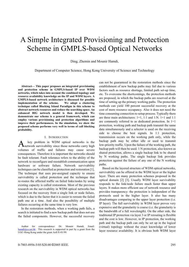
Figure 1: An example of IP over WDM network
Si
Si
Si
Si
Si
1
2
345
6
7
8
0.5 unit
0.5 unit
Figure 2: A new topology of the example network
An example of network topology is shown in Figure 1,where node 1, 2, 3, 4, 8 are integrated router/OXC nodes andnode 5, 6, 7 are plain OXCs. Based on the GMPLSframework, an optical channel ( -LSP) needs to be set up foreach request and the required bandwidth is reserved on linksof the -LSP path. The request to set up a -LSP can be defined as (Xµ, Yµ, µ) where Xµ and Yµ are distinct nodes of the network; µ is the required bandwidth. Since this is a circuit switched network, the only QoS requirement we
296

consider in this paper is bandwidth. Assume the bandwidthof a whole wavelength is 1 unit. A request (Xµ, Yµ, µ) is to berouted from node Xµ R to node Yµ R with the bandwidthrequirement µ 1 unit. If an optical channel is set up to reach the destination and this path involves nodes of OXCs, somecut through arcs (lightpaths) may be created to meet therequirement. The IP layer network topology will be changedin this case. For example, in figure 1, a traffic request arrives,requiring the bandwidth of 0.5 unit from node 1 to node 8.To simplify the example, we consider each fiber has onlyone wavelength. Assume a LSP path (1->5->3->4->7->8)has been found from node 1 to node 8 along the wavelengthw1. Because OXCs can only multiplex and demultiplextraffic requests with the bandwidth request of a wholewavelength, new lightpaths are set up to directly connectintegrated nodes. In figure 2, 2 new lightpaths (cut througharcs) are introduced to form a new topology. Notice only 0.5unit bandwidth is consumed along the path. The residual 0.5unit bandwidth is still available along the lightpath for future use. Those lightpaths are logical links in the IP layer. Theycan be released or re-setup according to traffic requests and resource availability.
III. BIG NETWORK MODEL
In this section, we give a brief introduction on theBlocking Island paradigm, which is used as a framework inthe proposed integrated scheme. The Blocking Island (BI)paradigm [6] provides an efficient way of abstractingresource (especially bandwidth) available in a communication network. An enhanced BIG (BlockingIsland Graph) network model is proposed to represent IP over WDM networks.
BI clusters parts of the network according to thebandwidth availability. A -BI for a node x is the set of allnodes of the network that can be reached from x using linkswith at least available bandwidth. For example, N1 inFigure 3 (a) is a 40-BI for node V1. We start with node V1.Then we add all the nodes which can be reached by linkswith at least 40 available bandwidth to form a 40-BlockingIsland N1.
-BI has some very useful properties. Below we list a few without proof (for a proof, please refer to [6]).
Unicity: there is one and only one -BI for a node. Thus ifS is the -BI for a node, S is the -BI for every node in thisblocking island.
Partition: -BI induces a partition of nodes in a network. Route existence: give a request d= (Xµ, Yµ, µ), it can be
satisfied if and only if the node xu and yu are in the sameu-BI.Inclusion: If i< j, the j-BI for a node is a subset of the
i-BI for the same node.
V1
L1(74)
V2
V3
V8
V4
V7
V14
V13
V12
V6
V11
V10
V5
L3(45)
L5(59)
V9
L4(12)
L6(9)
L13(80)
L12(62)
L17(30)
L19(7)
L14(63)
L9(5)
L11(17)L
8 (7)
L7(14)L18(94)
L10(43)
L15 (90)
L21(7)
L2(52)
L 16(35
)
L20(23
)
N1
N3
N2
N4
N5
N1{V1,V2,V3,V4}
N4{V5,V9}
N2{V7}
N5{V6,V11,V12}
N3{V8,V10,V13,V14}
{L4(12)}
{L9(5)}
{L6(9)}
{L7(
14)}
{L7(14)}
{L16(35),L20(23),L19(7)}
{L21 (7)}
(a) Network
(b) 40-BIG
Figure 3: (a) The NSFNet topology. N1= {V1, V2, V3, V4} is the 40-blocking island (40-BI) for node V1. The available bandwidth on a link is given in brackets. (b) 40-BIG
Using the concept of -BI, we can construct a recursive decomposition of Blocking Island Graphs in decreasingorder of s, e.g. 1> 2>…> n. We call this layered structureof Blocking Island Graphs a Blocking Island Hierarchy(BIH). For example, figure 3(b) is a 40-BIG. Based on figure3(b), we can build a 20-BIG if necessary.
With the abstract technique, instead of studying the wholenetwork topology, we focus our attention only on a smallpart. For example, given a traffic request (V1, V4, 40) in figure 3(a), according to the route existence property, the route is in 40-BI N1. In the N1 Blocking Island, differentrouting heuristic can be employed to find the route. If theroute is allocated, the available link capacity is decreased and the BIH may need to be modified. For example, in figure3(a), if we assign a route V1-->V3-->V2 with 40 bandwidth,the 40-BI N1 will be split into two 40-BIs: (V1, V2, V4) and (V3). Notice all the modification is actually localized andcarried out only within the N1 Blocking Island.
In order to apply the BI paradigm into the proposedscheme, we need to transform the network topology into a proper form. In [7], we propose a BIG network model torepresent WDM optical networks. It is not appropriate toapply this model directly since there are some differencebetween the modeling of IP over WDM networks and WDMnetworks. In the original BIG model, we assume a singlefiber network without wavelength converters. Eachconnection request needs to be allocated over a route andassigned one wavelength. It is modeled as a simplifiedblocking island graph with only one level of BIH. For IP
297
over WDM networks, the integrated router/OXC nodes havethe capacity of wavelength conversion. The traffic requestscan require any fraction of wavelength bandwidth. And itwill have multi-level layers of BIH according to different traffic requests.
1
2
3
4
51
(a)
2
4
3
5
(b)
1
1'
2'
4'
3'
5'2
Si
Si
Si
Si
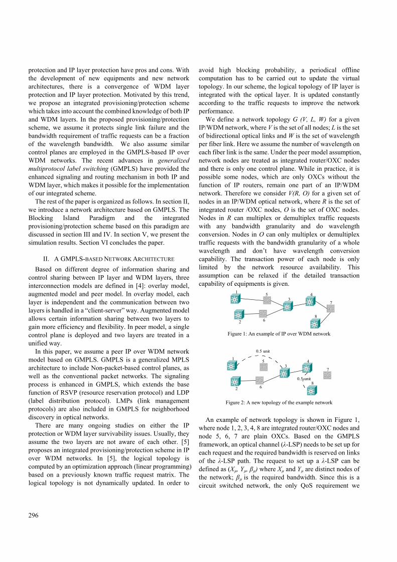
Figure 4: (a) An example of IP/WDM network (b) Representation of the network by enhanced BIG network model
To accommodate those variations, we propose an enhanced BIG network model to represent the IP over WDMnetwork. We assume a single fiber optical network and theset of wavelength on each fiber link is the same. Consider a network topology G (V, L, W) for a given IP/WDM network,where V=(R, O), R is the set of integrated router/OXC nodes,O is the set of OXC nodes; L is the set of bidirectional opticallinks and W is the set of wavelength per fiber link. The enhanced BIG network model can be obtained from a givennetwork topology G as follows. Firstly we replicate theoriginal topology of G |W| times. Each copy represents awavelength and has the same topology as the original IPover WDM network. Then we check integrated node r R .In the enhanced BIG model, node r has |W| copies as (r1,r2 …r|W|). Virtual links r1r2, r2r3 … r|W|-1 r|W| are then added toconnect corresponding nodes. Notice since those nodes like(r1, r2 …r|W|) are actually the same node, the virtual linksonly characterize the link connectivity with unlimitedbandwidth and have no weight (distance) in the routing andgrooming computation. An very simple example is given infigure 4, where nodes 1,2,3,4 are integrated router/OXCnodes and 5 is the OXC node. 2 wavelengths 1 2 per fiber isassumed.
Notice by converting the network topology into theenhanced BIG network model, we combine the WDM layerand IP layer into one network level. The previousindependent RWA (routing and wavelength assignment) inWDM layer and the IP routing in the logical layer aretransformed into one general routing problem in the BIGnetwork model. In the next section, based on the enhanced BIG network model, we propose a simple and effectiveprovisioning and protection scheme.
IV. AN INTEGRATED PROVISIONING/PROTECTION SCHEME
In this section, we propose an integrated provisioning and
protection scheme in IP over WDM network using the BIparadigm. The general idea of this scheme is very simple.Firstly we transform the network topology into the enhancedBIG network model. Unlike the scheme proposed in [5],where the virtual topology design is static and independentfrom the RWA process in the WDM layer, we treat RWAand IP layer routing in a unified way. We then build the BIHbased on the BIG network model and incoming trafficstatistics. Upon receiving a traffic request, we identify the proper blocking island in the BIH and check route existence.The working path and the backup protection path will then be searched in the blocking island instead of the wholenetwork.
BIH ConstructionAfter the BIG modeling, we need to build more levels of
BIH based on different traffic bandwidth requests tofacilitate future resource allocation. The most primitive ideais to build a new level once there is a different trafficbandwidth request. Although this method can accuratelyabstract network resource availability and minimize thesearch space, the disadvantages are obvious: It may not be responding fast enough to handle large amount of thedynamic traffic. And too many levels also make thealgorithm not scale well. Our idea is to pick uprepresentative bandwidth according to incoming traffic statistics for a certain period.
Blocking Island Assigning Procedure After predefining the proper BIH, when new traffic
request arrives, we pick up the closest BIG level in the BIHto apply routing heuristics. Consider a request Du= (Xµ, Yµ,
µ) where Xµ and Yµ are source node and destination node, µ
is the required bandwidth, using the BI Routing Existenceproperty we immediately know whether the request can besatisfied or not based on a µ-BIG without any computing.As we stated before, the BIH building at disposal is notdesirable because of the time and high maintenance cost.With the predefined limited levels of BIH, it is possible wedon’t have an exact match of BIG but we can still check the route existence of most requests much faster than a full network search. The route existence screening process isillustrated by an example. Assume a predefined H level BIH ( 1, 2… H), where i is the bandwidth level of thecorresponding BIG level and 1< 2<…< H. If µ is equal toany predefined bandwidth value i the result can be obtainedimmediately.
If µ > H, we assign Du to H-BIG. Then we check whether Xµ and Yµ are in the same BI of H-BIG. If the answer is no, the request is blocked. If yes, we have to do afurther check on this BI using Dijkstra’s algorithm or a
298

link-state routing protocol. If µ < 1, we assign Du to 1-BIG. Then we check
whether Xµ and Yµ are in the same BI of 1-BIG. If the answer is yes, the route exists. If no, we have to do a further check on the whole network topology using Dijkstra’s algorithm or a link-state routing protocol. This is the worst case in our screening process.
If 1 < µ < H, say i < µ < i+1 (1 i H-1), we first check whether Xµ and Yµ are in the same BI of i+1-BIG. If the answer is yes, the route exists. If not, we then check whether Xµ and Yµ are in the same BI of i-BIG. If they are in the same BI, we have to do a further check on this BI using Dijkstra’s algorithm or a link-state routing protocol. If not, the request is blocked.
Consider all the scenarios, except in the worst case we have to check the whole network topology, normally, we can tell the route existence immediately or only need to do searching in a much smaller space. By analyzing the traffic statistics and carefully distribute the BI hierarchy, we can reduce the computation cost significantly and identify the bottleneck links more efficiently.
BI Provisioning/Protection Scheme After the network has been transformed into an enhanced
BIG network with the corresponding BIH constructed, below we introduce the working path setup algorithm and backup path setup algorithm.
1) Setup of the Working Path Given a traffic request a) Update BIH after decreasing the link bandwidth
occupied by other primary paths and removing the links in backup paths;
b) Assign the traffic request to a blocking island of the BIH;
c) A routing heuristic called Minimum Splitting (MS) [7] is employed to find the working path. The basic idea is to find a route which causes the minimum splitting of the original blocking island.
If the working path is available, the resource availability of each link and BIH are updated. The working path is set up as the primary active path. Concurrently the protection path allocation is started.
2) Setup of the Backup Path Now we have a working path P.a) Notice the backup path must be link-disjointed form the
working path P. We need to remove links used in any working path or any backup path whose working path share common links with P. Then we update BIH;
b) Assign the traffic request to a blocking island of the
BIH;c) MS heuristic is employed to find the backup path. Similar to the idea proposed in [5], when initiating the
protection process, we can add a bandwidth fraction threshold T to provide differentiated reliability service, where T represents the fraction of traffic that needs to be protected.
Complexity analysis Define a network topology G (V, L, W) for a given IP over
WDM network, where V is the set of nodes, L is the set of links and W is the set of wavelengths per fiber link. Assume the set of wavelengths on each fiber link is the same. After transforming into the enhanced BIG network, the number of nodes in the BIG network is |VW| and the predefined BIH level is H. Assume V=(R, O), R is the set of integrated router/OXC nodes, O is the set of OXC nodes. The number of links is equal to |LW|+|R(|W|-1)|, |R(|W|-1)| is the number of added virtual links which are regarded as having unlimited bandwidth and no weight. The most common operation in the integrated algorithm is the Blocking Island construction. The -BI for a given node x of a network can be obtained with a simple greedy algorithm. Starting with an initial set {x}, we recursively add every node to the set, if this node can be reached from any node in the set by a link that has at least available bandwidth. In the worst case, this construction process will examine all links. Therefore, the -BI construction process is linear in O(n), where n is the
number of actual links in the network (n=|LW|). The time of constructing one level of BIG is O (mn), where m is the number of nodes and n is the number of links in the network (m=|VW|, n=|LW|). The building time of BIH is O (Hmn).Given a good distribution of BIH levels, usually the route existence check time is equal to the time of constructing one level of BIG. In the worst case, it has to compute the route in the whole enhance BIG network using Dijkstra’s algorithm to decide whether the route is available or not. If the request can be satisfied, the running time is equal to the combination of 1) K alternate shortest paths; 2); Splitting cost computation 3) BIH update. That is K*O(nlg(m))+K*O(Hmn)+O(Hmn),where K is a constant and H is a constant, so the algorithm running time is linear in O(mn).
V. SIMULATION RESULTS
In this section, we evaluate the performance of the proposed scheme via simulation in a random generated network topology. In the simulation, the lightpath requests are randomly generated among all node pairs. The wavelength continuity constraint is considered if it is not an
299

integrated router/OXC node. We assume that thepropagation delay on any link is the same (e.g. 50ms).Single-link failures are considered as the set of failurescenarios. We do not consider multi-failure scenarios. Thenetwork topology is shown in figure 5, consisting of 15 nodes and 29 links. 6 nodes are chosen as integratedrouter/OXC nodes.
V15
V13
V11
V14
V10
V12
V9V6
V8
V7
V5
V4
V3
V1
V2
Figure 5: A random generated network topology
So we have 30 pairs of ingress/egress nodes. The trafficpattern is dynamic. Calls arrive at each ingress/egress nodepair according to an independent Poisson process. The session holding time is exponentially distributed. Thebandwidth requirement is uniformly distributed between 0.1and 1 unit. We assume the protection ratio T is 0.8, whichmeans the bandwidth of protection path is only 80 percent ofthe working path. In our simulation, extensive tests are carried out to ensure a steady state.
10 20 30 40 50 60 701E-3
0.01
0.1
Bloc
king
Pro
babi
lity
Load (Erlang)
BI WSP ISP
Figure 6: The call blocking probability with the number of wavelength 4
We compare the performance of our scheme (BI) with the WDM shared protection scheme (WSP) and an integratedshared protection scheme (ISP) proposed in [5]. Theperformance of those algorithms is compared in terms of two objectives. One is to maximize the number of successfullybuilt primary path and the corresponding protection pathbased on the same network resources. In our simulation, we use blocking probability as the parameter. Under the same
traffic load and network topology, the lower the blockingprobability is, the better the performance is. The otherobjective is to minimize average propagation delay onprimary lightpath.
Notice in ISP scheme, the lightpath is computed using theshortest path algorithm with first-fit wavelength assignmentand the single-hop lightpath allocation is used to assignworking path. In our scheme, we predefine the BIH with0.1-BIG, 0.3-BIG, 0.5-BIG and 0.8-BIG. The simulationresults are shown in figure 6 and figure 7 with the number ofwavelengths 4 and 8 respectively. In both cases, our schemeoutperforms the other two and has a much lower blockingprobability. The WDM shared protection performs the worstbecause its bandwidth granularity is coarse (full wavelength protection) and has the wavelength continuity constraint.
20 30 40 50 60 70 80 901E-3
0.01
0.1Bl
ocki
ng P
roba
bilit
y
Load (Erlang)
BI WSP ISP
Figure 7: The call blocking probability with the number of wavelength 8
Figure 8 is the average propagation delay (APD) on primary lightpaths vs the traffic load. The wavelength is 4.With the increase of traffic load, the average propagation delay with ISP algorithm changes little, because the shortest path between a pair of nodes is always used as a primarypath. The WDM shared protection scheme gives the largestpropagation delay because the route is usually long due to wavelength constraint and coarse bandwidth granularity. In our algorithm, with the increasing traffic load, more andmore alternate routes will be used and longer alternate routes may be used for conserving limited network resources, which in turn causes the higher average propagation delay.Notice usually our two objectives are contradictory. Under the same condition, the more lightpath requests a networkcan satisfy, the longer the average propagation delaybecomes.
300

10 20 30 40 50 60 70155
160
165
170
175
180
Avg.
Pro
paga
tion
Del
ay (m
s)
Load (Erlang)
BI WSP ISP
Figure 8: The average propagation delay of primary lightpaths with the number of wavelength 4
VI. CONCLUSION
The primary contribution of this paper is to develop adynamic and integrated provisioning/protection scheme inGMPLS-based IP over WDM networks. Using the proposed scheme, we are able to set up an efficient survivable IP over WDM networks. This scheme is proposed based on anabstraction technique called the Blocking Island Paradigm.We introduce the basic idea of blocking island and discussthe process of converting the network topology to theenhanced BI network model. The main advantage of ourscheme is that it uses a combined view of IP layer and WDMlayer to do IP routing and RWA a single routing domain.Also we show our scheme is a general framework which canreduce the searching space and accommodate variousprovisioning/protection heuristics. The simulation resultsprove its effectiveness.
REFERENCES
[1] V.Sharma et al., Framework for MPLS-based recovery, IETF draft,draft-ietf-mpls-recovery-frmwrk-03.txt, July 2001.
[2] S. Ramamurthy and B. Mukherjee, “Survivable WDM MeshNetworks,” Infocom’99, Mar. 99.
[3] E. Modiano, and A. Narula-Tam, “Survivable Routing of LogicalTopologies in WDM Networks,”OFC’01, Mar. 2001.
[4] B. Rajagopalan et al, “IP over Optical Networks: ArchitecturalAspects,” IEEE Commun. Mag., vol. 38 no. 9, Sept. 2000, pp. 94-102.
[5] Y. Ye, et al, “A Simple Dynamic Integrated Provisioning/ProtectionScheme in IP over WDM Networks”, IEEE Commun. Mag., Nov.2001, pp. 174-182.
[6] C. R. Frei, “Abstraction Techniques for Resource Allocation in Communication Networks,” PhD thesis, Swiss Federal Institute of Technology – Lausanne, 2000.
[7] D. Zhemin and M. Hamdi, "A Simple and Intelligent Routing andWavelength Assignment Algorithm for All-Optical Networks,” SPIEOpticom, 2001, pp. 210-226.
301