Embed Size (px)
Citation preview
Progress In Electromagnetics Research, Vol. 123, 47–65, 2012
A SIMPLE AND COMPACT PLANAR ULTRA WIDE-BAND ANTENNA WITH SINGLE OR DUAL BAND-NOTCHED CHARACTERISTICS
D. Zhou1, *, S. Gao1, F. Zhu1, R. A. Abd-Alhameed2, andJ. D. Xu3
1Surrey Space Centre, University of Surrey, Guildford, UK2Mobile and Satellite Communications Research Centre, University ofBradford, Bradford, UK3Northwestern Polytechnical University, Xi’an, P. R. China
Abstract—A printed monopole ultra wideband (UWB) antenna withfrequency band-notched characteristics is proposed and investigated.The antenna consists of a half-disk shaped structure combined withan inverted isosceles trapezoid structure. To achieve the frequencyband notched characteristics, an open-ended thin slit with a lengthof about one quarter guided wavelength is inserted on the radiator.Multiple slits can be employed to realize multiple frequency bandnotched characteristics. To validate the concept, two prototypes aredesigned, fabricated and tested. The first is a single band notchedUWB antenna whereas the second is a dual band notched UWBantenna. The simulated and measured results of both antennas arepresented shown a reasonable agreement between them. The resultsalso confirm the proposed UWB antenna design can achieve superiordual band-notch performance at desired frequency bands.
1. INTRODUCTION
Ultra wideband (UWB) communications systems have drawn increas-ing attention in the past decade. It has now become a promising tech-nology offering high performance for both the indoor and outdoor wire-less communication systems, which allow low cost, low power consump-tion and high data rate. For many years, UWB technology was a widelyapplied technology for radar and remote sensing applications [1, 2]. In
Received 11 October 2011, Accepted 4 December 2011, Scheduled 12 December 2011* Corresponding author: Dawei Zhou ([email protected]).
48 Zhou et al.
2002, the Federal Communication Commission (FCC) has allocatedfrequency band from 3.1 to 10.6GHz for commercial UWB communi-cation systems [3]. The research on wireless communications systemsusing UWB technology has become a popular topic since then. How-ever, the design of a UWB antenna with a small size, low cost and highperformance is still a challenging task.
The UWB antenna is required to achieve impedance matching overa UWB frequency range, stable radiation patterns, and linear phase.Many UWB antennas, which fulfill these design requirements, havebeen reported in the literature [4]. Generally speaking, printed typeof UWB antennas are the dominating type among most of studies sofar reported, in addition to the type of three dimensional designs usingmetallic plates [5]. This is because printed antennas may have goodadvantages such as small size, easy fabrication and they can be madecompatible to the rest of the RF front ends and be implemented on thesame PCB circuitry, which results in reducing the cost of the antennafabrication.
In recent years, a new challenge in UWB antenna designs is torealize frequency band-notched characteristics. This is for eliminatingpossible interference between 5 to 6 GHz (5.15–5.35GHz and 5.725–5.825GHz), that is already reserved for the existing Wireless LocalArea Network (WLAN) communications systems. This type ofinterference problem can be eliminated by adding extra filters, whichwill increase the size and cost; however, on the other hand, it isdesirable to have a small-size UWB antenna with frequency bandnotched characteristics. Several methods have been developed toachieve UWB antennas with band-notched characteristics in whichthey have included: different shapes of slots (ex. U-shaped, V-shaped,arc-shaped, or ring-shaped) are inserted on the printed antenna orits associated ground plane to obtain a notched frequency band [6–11]; adding parasitic elements near the printed antenna [12–15]; usingdefected ground structure (DGS) [16] or electromagnetic band-gap(EBG) [17]; introducing simple open-end slits on the antenna structure,which are usually quarter wavelength in length, frequency notches cantherefore be obtained [18]. Moreover, dual band-notched frequency canbe realized by adopting and combining the foregoing methods [19–21].
In this paper, a simple, compact and uniplanar printed monopoleantenna operated with single or multiple band-notched characteristicsis proposed and discussed. The antenna configuration employsa combination of circular-shaped structure of an inverted isoscelestrapezoid structure, in order to realize good impedance matching overthe UWB frequency range. The technique of slits loading on theradiator is applied to achieve single or multiple frequency band notched
Progress In Electromagnetics Research, Vol. 123, 2012 49
characteristics. Two prototypes are designed and developed, to confirmthe operation of single-band-notched and dual-band-notched responses.Finally, analysis of the calculated and measured results of the twoprototypes are presented and discussed.
2. DESIGN OF UWB ANTENNA WITH SINGLEBAND-NOTCHED CHARACTERISTICS
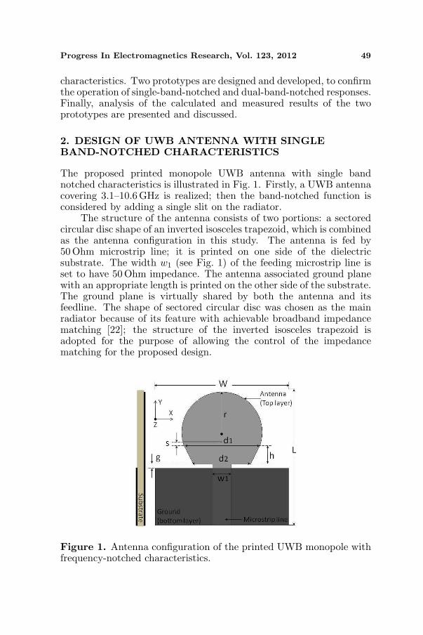
The proposed printed monopole UWB antenna with single bandnotched characteristics is illustrated in Fig. 1. Firstly, a UWB antennacovering 3.1–10.6 GHz is realized; then the band-notched function isconsidered by adding a single slit on the radiator.
The structure of the antenna consists of two portions: a sectoredcircular disc shape of an inverted isosceles trapezoid, which is combinedas the antenna configuration in this study. The antenna is fed by50Ohm microstrip line; it is printed on one side of the dielectricsubstrate. The width w1 (see Fig. 1) of the feeding microstrip line isset to have 50 Ohm impedance. The antenna associated ground planewith an appropriate length is printed on the other side of the substrate.The ground plane is virtually shared by both the antenna and itsfeedline. The shape of sectored circular disc was chosen as the mainradiator because of its feature with achievable broadband impedancematching [22]; the structure of the inverted isosceles trapezoid isadopted for the purpose of allowing the control of the impedancematching for the proposed design.
Figure 1. Antenna configuration of the printed UWB monopole withfrequency-notched characteristics.
50 Zhou et al.
The proposed compact printed monopole UWB antenna (withouta band notch) is successfully developed. Subsequently, a methodof producing band-notched characteristics is introduced, by insertinga horizontally open-ended thin slit with approximated length aboutone quarter-wavelength guided wave at the desired notched frequency(fnotch). The position of this slit is placed near the area of the invertedisosceles trapezoid. This is due to the fact that most of surface currentis mainly distributed around the area between the antenna groundplane and the lower area of the inverted isosceles trapezoid. The firstresonant frequency (flow ) at the lower edge of operating band is relatedto the vertical length (r + h) of the proposed antenna, which can beapproximately calculated by Equation (1). Moreover, the notched-band frequency (fnotch) of the inserted quarter wavelength open-endedslit resonator is given by Equation (2).
flow =c
4(r + h)√εeff(1)
fnotch =c
4ls√
εeff(2)
where c is the speed of light, r and h are shown in Fig. 1, ls is thelength of the open-ended slit and εeff is defined as [7]:
εeff =εr + 1
2(3)
The antenna is simulated and designed using Ansoft HFSS [23].
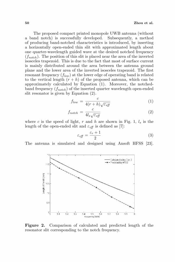
Figure 2. Comparison of calculated and predicted length of theresonator slit corresponding to the notch frequency.
Progress In Electromagnetics Research, Vol. 123, 2012 51
Table 1. Dimensions of the antenna parameters of the proposeddesign.
Parameters
W L w1 d1 d2 ls h g r s
Dimensions (mm) 35 35 4.9 15 20 10.1 5 1 14 0.8
The relationship between the predicted notch frequency and thecorresponding quarter wavelength resonator slit length is studied first.The results predicted by the HFSS simulator are compared to theones calculated by the Equation (2), as shown in Fig. 2. As can beseen, the curves from two sets of results show similar slope tendencyagainst the frequency, but different in the slit length correspondingto each frequency. This is mainly because the approximation adoptedwhen calculating the relative dielectric permittivity in Equation (2).Nevertheless, it is noted that the parameter ls is found to be 10.1 mmin order to obtain a notched frequency at 5.59 GHz. Other parameters,including r, s, d2 and ls are also important parameters in the design.Table 1 presents the detailed dimensions of each antenna parametersof the final design.
3. RESULTS ANALYSIS FOR SINGLE BAND-NOTCHEDDESIGN
The proposed antenna with single band-notch characteristic is firstlystudied by simulation and then in a hardware realization. Forfabrication, prototypes of the proposed design with optimized keyparameters (e.g., r, s and d2), including the design with and withoutfrequency notch respectively, are built up on the Duroid 5880 substratewith dielectric constant of 2.2 and thickness of 1.575mm. In thissection, the characteristics of the proposed design is analysed in termsof antenna voltage standing wave ratio (VSWR), input impedance,radiation patterns, power gain and group delay, in addition to theresults in time domain analysis. The measured results of the fabricatedprototype is presented and compared with the theoretical predictions.
3.1. Analysis in Frequency Domain
The antenna input matching of the fabricated prototype is evaluatedat the defined UWB frequency band. The measured and simulatedVSWR of the proposed antenna with frequency band-notched feature

52 Zhou et al.
is presented in Fig. 3, where their VSWR was compared to those ofthe design without band-notch. As can be seen in Fig. 3, the proposedantenna exhibits ultra wideband impedance behavior, the measuredand simulated results agreed well in both cases. Moreover, a clearnotched frequency appears at frequency of 5.6 GHz with measuredpeak VSWR of over 7, which suggests a good rejection level at thisfrequency.
Figure 3. Comparison of simulated and measured antenna VSWR forsingle notched-band design.
Figure 4. Comparison of simulated surface current distribution forthe antenna with and without frequency-notched feature.
Progress In Electromagnetics Research, Vol. 123, 2012 53
The surface current distribution at the notched frequency of theproposed design is examined, as presented in Fig. 4. As can be seen,the surface current distributes over the antenna and the ground planefor the antenna without notch band, whereas, the amplitude of surfacecurrent is increased dramatically for the band-notched design. It isnotable that the surface current is mainly concentrated around theregion of the slit on the antenna. This implies the band rejection effectdue to the fact that the standing wave is realized. As a result, the sliteffectively reflects back the RF signal to the antenna input port. Thus,the radiation of the proposed antenna is effectively suppressed at thenotched frequency. In addition, current distributions at other UWB
(a)
(b)
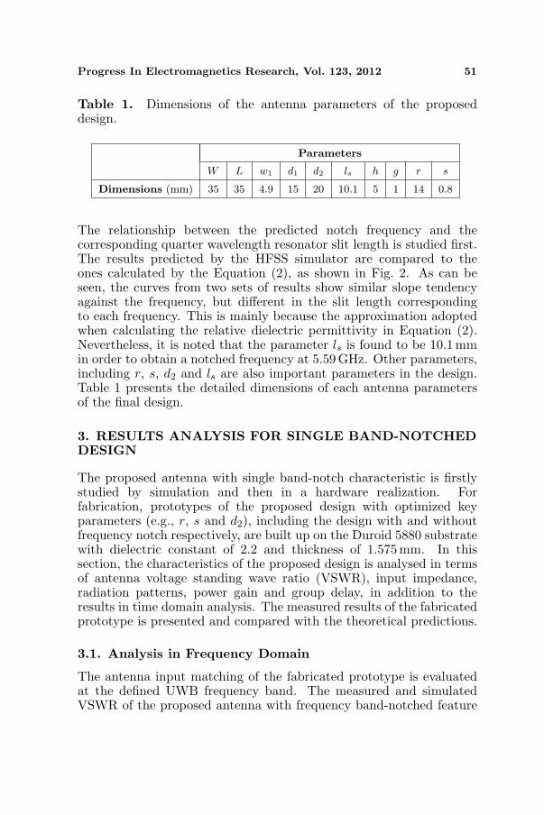
Figure 5. Radiation patterns of the proposed antenna for (a) E planeand (b) H plane at f = 4 GHz and f = 8 GHz (‘ooo’ representsmeasured Eθ, ‘—’ simulated Eθ, ‘xxx’ measured Eφ and ‘- - - -’simulated Eφ).
54 Zhou et al.
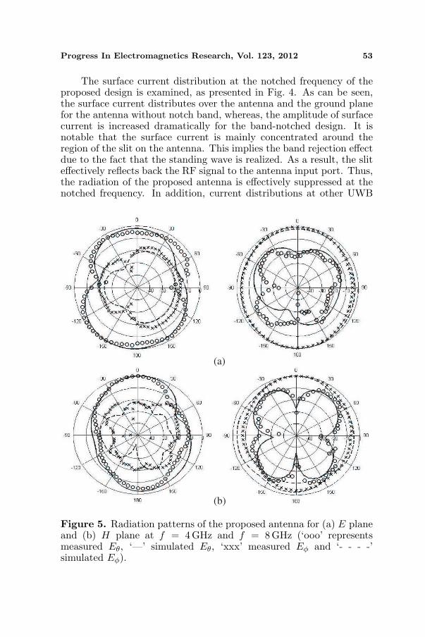
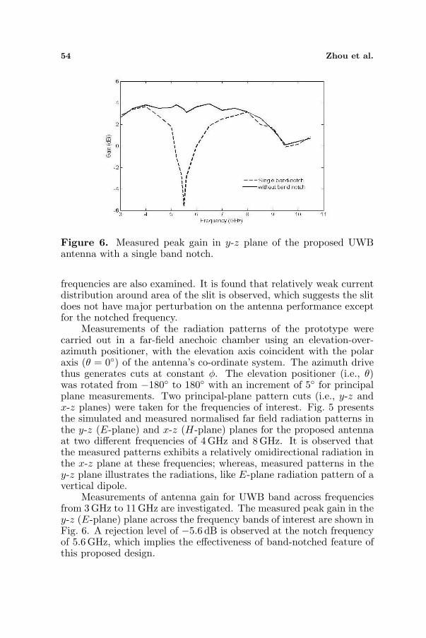
Figure 6. Measured peak gain in y-z plane of the proposed UWBantenna with a single band notch.
frequencies are also examined. It is found that relatively weak currentdistribution around area of the slit is observed, which suggests the slitdoes not have major perturbation on the antenna performance exceptfor the notched frequency.
Measurements of the radiation patterns of the prototype werecarried out in a far-field anechoic chamber using an elevation-over-azimuth positioner, with the elevation axis coincident with the polaraxis (θ = 0◦) of the antenna’s co-ordinate system. The azimuth drivethus generates cuts at constant φ. The elevation positioner (i.e., θ)was rotated from −180◦ to 180◦ with an increment of 5◦ for principalplane measurements. Two principal-plane pattern cuts (i.e., y-z andx-z planes) were taken for the frequencies of interest. Fig. 5 presentsthe simulated and measured normalised far field radiation patterns inthe y-z (E-plane) and x-z (H-plane) planes for the proposed antennaat two different frequencies of 4 GHz and 8 GHz. It is observed thatthe measured patterns exhibits a relatively omidirectional radiation inthe x-z plane at these frequencies; whereas, measured patterns in they-z plane illustrates the radiations, like E-plane radiation pattern of avertical dipole.
Measurements of antenna gain for UWB band across frequenciesfrom 3GHz to 11GHz are investigated. The measured peak gain in they-z (E-plane) plane across the frequency bands of interest are shown inFig. 6. A rejection level of −5.6 dB is observed at the notch frequencyof 5.6 GHz, which implies the effectiveness of band-notched feature ofthis proposed design.
Progress In Electromagnetics Research, Vol. 123, 2012 55
3.2. Analysis in Time Domain
Group delay is an important parameter to characterize the degree ofdistortion of the pulse signal for UWB impulse-based system. It isdesired that the group delay response is stable over the UWB frequencyband. In addition, the shape of the transmitted pulse should not bedistorted by the antenna.
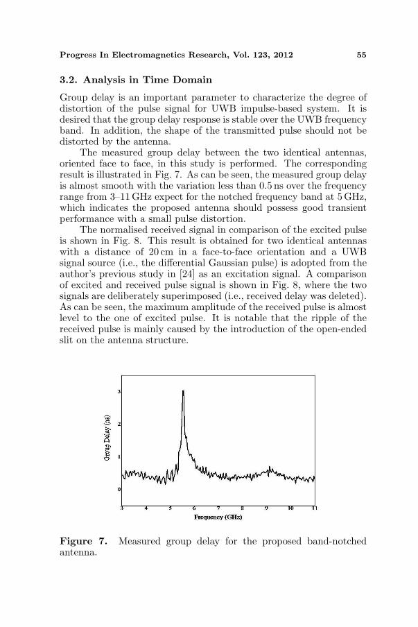
The measured group delay between the two identical antennas,oriented face to face, in this study is performed. The correspondingresult is illustrated in Fig. 7. As can be seen, the measured group delayis almost smooth with the variation less than 0.5 ns over the frequencyrange from 3–11 GHz expect for the notched frequency band at 5 GHz,which indicates the proposed antenna should possess good transientperformance with a small pulse distortion.
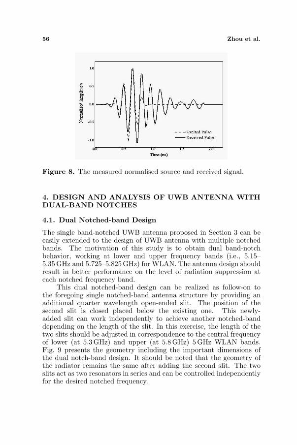
The normalised received signal in comparison of the excited pulseis shown in Fig. 8. This result is obtained for two identical antennaswith a distance of 20 cm in a face-to-face orientation and a UWBsignal source (i.e., the differential Gaussian pulse) is adopted from theauthor’s previous study in [24] as an excitation signal. A comparisonof excited and received pulse signal is shown in Fig. 8, where the twosignals are deliberately superimposed (i.e., received delay was deleted).As can be seen, the maximum amplitude of the received pulse is almostlevel to the one of excited pulse. It is notable that the ripple of thereceived pulse is mainly caused by the introduction of the open-endedslit on the antenna structure.
Figure 7. Measured group delay for the proposed band-notchedantenna.
56 Zhou et al.
Figure 8. The measured normalised source and received signal.
4. DESIGN AND ANALYSIS OF UWB ANTENNA WITHDUAL-BAND NOTCHES
4.1. Dual Notched-band Design
The single band-notched UWB antenna proposed in Section 3 can beeasily extended to the design of UWB antenna with multiple notchedbands. The motivation of this study is to obtain dual band-notchbehavior, working at lower and upper frequency bands (i.e., 5.15–5.35GHz and 5.725–5.825GHz) for WLAN. The antenna design shouldresult in better performance on the level of radiation suppression ateach notched frequency band.
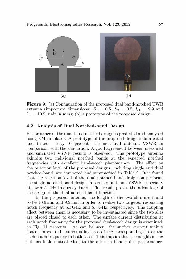
This dual notched-band design can be realized as follow-on tothe foregoing single notched-band antenna structure by providing anadditional quarter wavelength open-ended slit. The position of thesecond slit is closed placed below the existing one. This newly-added slit can work independently to achieve another notched-banddepending on the length of the slit. In this exercise, the length of thetwo slits should be adjusted in correspondence to the central frequencyof lower (at 5.3 GHz) and upper (at 5.8 GHz) 5 GHz WLAN bands.Fig. 9 presents the geometry including the important dimensions ofthe dual notch-band design. It should be noted that the geometry ofthe radiator remains the same after adding the second slit. The twoslits act as two resonators in series and can be controlled independentlyfor the desired notched frequency.
Progress In Electromagnetics Research, Vol. 123, 2012 57
(a) (b)
Figure 9. (a) Configuration of the proposed dual band-notched UWBantenna (important dimensions: S1 = 0.5, S2 = 0.5, ls1 = 9.9 andls2 = 10.9; unit in mm); (b) a prototype of the proposed design.
4.2. Analysis of Dual Notched-band Design
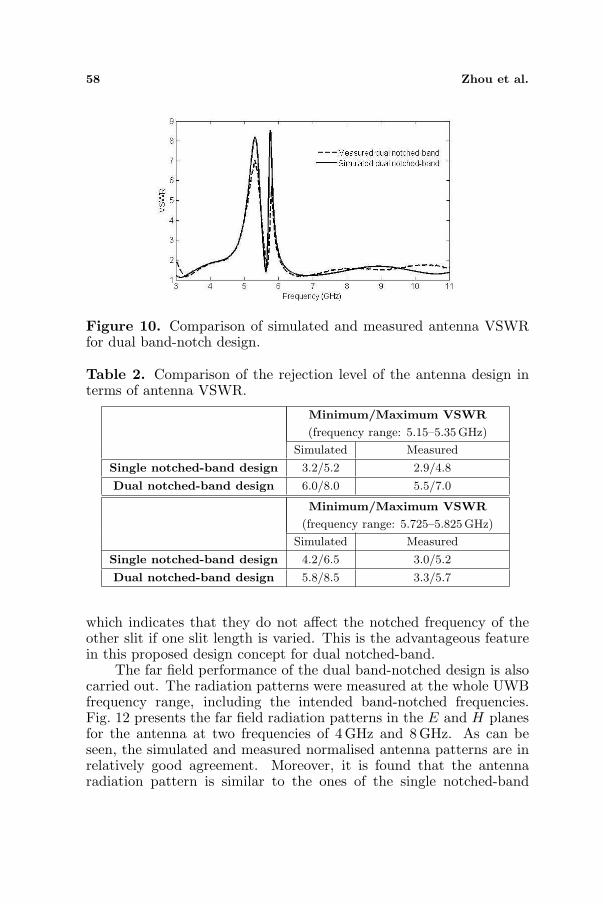
Performance of the dual-band notched design is predicted and analysedusing EM simulator. A prototype of the proposed design is fabricatedand tested. Fig. 10 presents the measured antenna VSWR incomparison with the simulation. A good agreement between measuredand simulated VSWR results is observed. The prototype antennaexhibits two individual notched bands at the expected notchedfrequencies with excellent band-notch phenomenon. The effect onthe rejection level of the proposed designs, including single and dualnotched-band, are compared and summarised in Table 2. It is foundthat the rejection level of the dual notched-band design outperformsthe single notched-band design in terms of antenna VSWR, especiallyat lower 5GHz frequency band. This result proves the advantage ofthe design of the dual notched-band function.
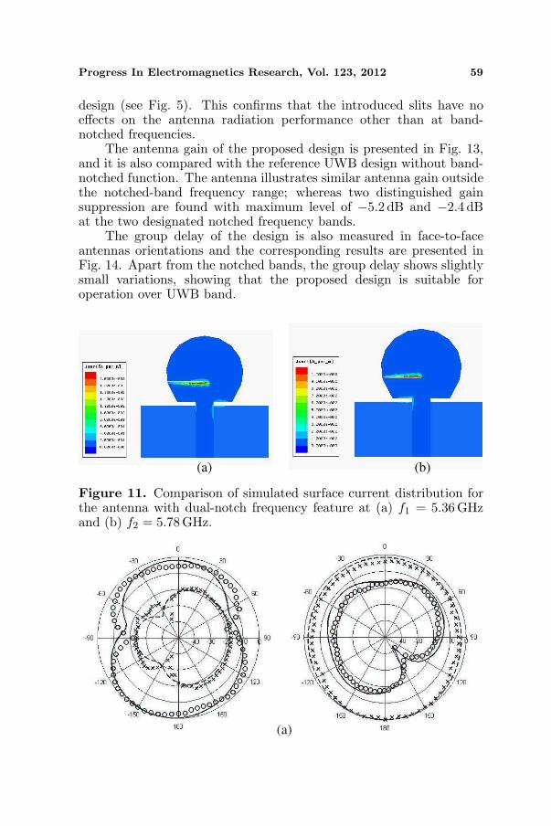
In the proposed antenna, the length of the two slits are foundto be 10.9 mm and 9.9mm in order to realise two targeted resonatingnotch frequency at 5.3 GHz and 5.8GHz, respectively. The couplingeffect between them is necessary to be investigated since the two slitsare placed closed to each other. The surface current distribution ateach notch frequency for the proposed dual-notch design is examined,as Fig. 11 presents. As can be seen, the surface current mainlyconcentrates at the surrounding area of the corresponding slit at theeach notch frequency in both cases. This implies that the neighbouringslit has little mutual effect to the other in band-notch performance,
58 Zhou et al.
Figure 10. Comparison of simulated and measured antenna VSWRfor dual band-notch design.
Table 2. Comparison of the rejection level of the antenna design interms of antenna VSWR.
Minimum/Maximum VSWR
(frequency range: 5.15–5.35 GHz)
Simulated Measured
Single notched-band design 3.2/5.2 2.9/4.8
Dual notched-band design 6.0/8.0 5.5/7.0
Minimum/Maximum VSWR
(frequency range: 5.725–5.825GHz)
Simulated Measured
Single notched-band design 4.2/6.5 3.0/5.2
Dual notched-band design 5.8/8.5 3.3/5.7
which indicates that they do not affect the notched frequency of theother slit if one slit length is varied. This is the advantageous featurein this proposed design concept for dual notched-band.
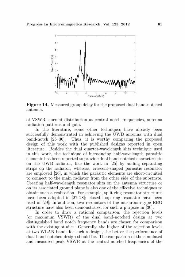
The far field performance of the dual band-notched design is alsocarried out. The radiation patterns were measured at the whole UWBfrequency range, including the intended band-notched frequencies.Fig. 12 presents the far field radiation patterns in the E and H planesfor the antenna at two frequencies of 4 GHz and 8 GHz. As can beseen, the simulated and measured normalised antenna patterns are inrelatively good agreement. Moreover, it is found that the antennaradiation pattern is similar to the ones of the single notched-band
Progress In Electromagnetics Research, Vol. 123, 2012 59
design (see Fig. 5). This confirms that the introduced slits have noeffects on the antenna radiation performance other than at band-notched frequencies.
The antenna gain of the proposed design is presented in Fig. 13,and it is also compared with the reference UWB design without band-notched function. The antenna illustrates similar antenna gain outsidethe notched-band frequency range; whereas two distinguished gainsuppression are found with maximum level of −5.2 dB and −2.4 dBat the two designated notched frequency bands.
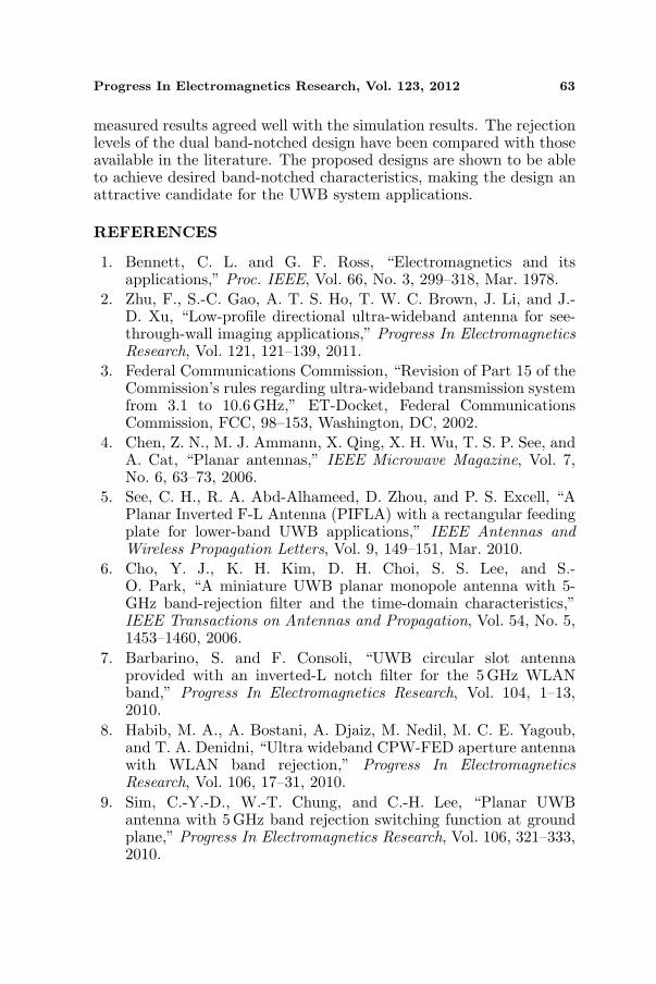
The group delay of the design is also measured in face-to-faceantennas orientations and the corresponding results are presented inFig. 14. Apart from the notched bands, the group delay shows slightlysmall variations, showing that the proposed design is suitable foroperation over UWB band.
(a) (b)
Figure 11. Comparison of simulated surface current distribution forthe antenna with dual-notch frequency feature at (a) f1 = 5.36 GHzand (b) f2 = 5.78GHz.
(a)

60 Zhou et al.
(b)
Figure 12. Radiation patterns of the dual band-notched antenna for(a) E plane and (b) H plane at f = 4 GHz and f = 8GHz (‘ooo’represents measured Eθ, ‘—’ simulated Eθ, ‘xxx’ measured Eφ and ‘-- - -’ simulated Eφ).
Figure 13. Measured peak gain in y-z plane of the proposed dualband-notched design.
4.3. Discussion and Comparison of Dual Notched-bandDesign
In this study, the simple and compact dual band-notched UWBantenna has been realised using two quarter-wavelength slits, whichare placed close to each other with slight difference in length in orderto generate band-notched function at the desired WLAN frequencybands. The antenna performances have been characterised in terms
Progress In Electromagnetics Research, Vol. 123, 2012 61
Figure 14. Measured group delay for the proposed dual band-notchedantenna.
of VSWR, current distribution at central notch frequencies, antennaradiation patterns and gain.
In the literature, some other techniques have already beensuccessfully demonstrated in achieving the UWB antenna with dualband-notch [25–30]. Thus, it is worthy comparing the proposeddesign of this work with the published designs reported in openliterature. Besides the dual quarter-wavelength slits technique usedin this work, the technique of introducing half-wavelength parasiticelements has been reported to provide dual band-notched characteristicon the UWB radiator, like the work in [25] by adding separatingstrips on the radiator; whereas, crescent-shaped parasitic resonatorare employed [26], in which the parasitic elements are short-circuitedto connect to the main radiator from the other side of the substrate.Creating half-wavelength resonator slits on the antenna structure oron its associated ground plane is also one of the effective techniques toobtain such a realisation. For example, split ring resonator structureshave been adopted in [27, 28]; closed loop ring resonator have beenused in [29]; In addition, two resonators of the mushroom-type EBGstructure have also been demonstrated for such a purpose in [30].
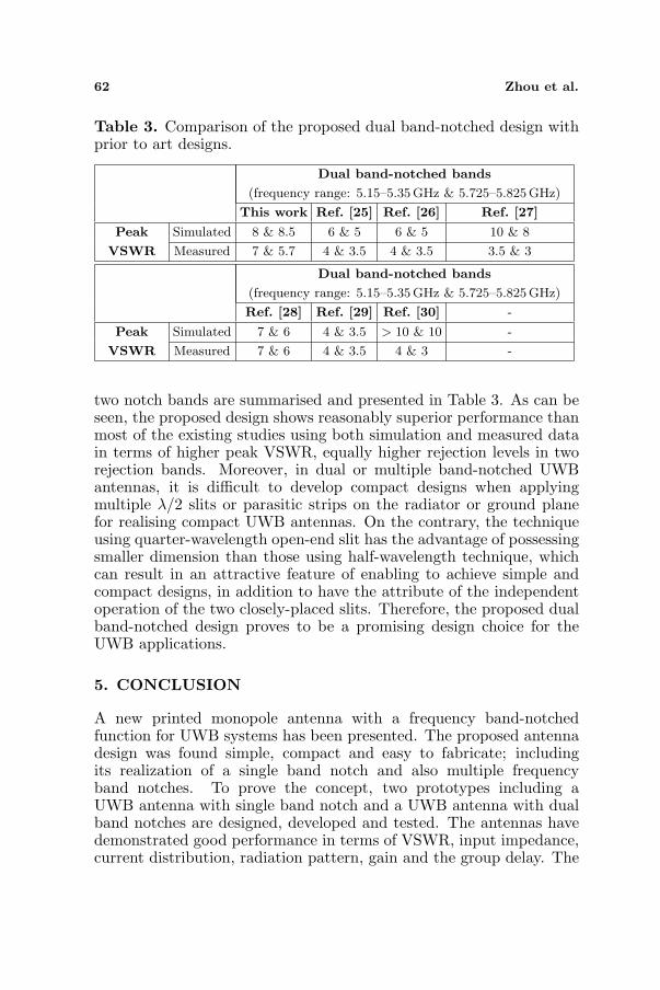
In order to draw a rational comparison, the rejection levels(or maximum VSWR) of the dual band-notched design at twodistinguished band notch frequency bands are chosen for comparisonwith the existing studies. Generally, the higher of the rejection levelsat two WLAN bands for such a design, the better the performance ofdual band-notched design should be. The comparison of the simulatedand measured peak VSWR at the central notched frequencies of the
62 Zhou et al.
Table 3. Comparison of the proposed dual band-notched design withprior to art designs.
Dual band-notched bands
(frequency range: 5.15–5.35GHz & 5.725–5.825 GHz)
This work Ref. [25] Ref. [26] Ref. [27]
Peak
VSWR
Simulated 8 & 8.5 6 & 5 6 & 5 10 & 8
Measured 7 & 5.7 4 & 3.5 4 & 3.5 3.5 & 3
Dual band-notched bands
(frequency range: 5.15–5.35GHz & 5.725–5.825 GHz)
Ref. [28] Ref. [29] Ref. [30] -
Peak
VSWR
Simulated 7 & 6 4 & 3.5 > 10 & 10 -
Measured 7 & 6 4 & 3.5 4 & 3 -
two notch bands are summarised and presented in Table 3. As can beseen, the proposed design shows reasonably superior performance thanmost of the existing studies using both simulation and measured datain terms of higher peak VSWR, equally higher rejection levels in tworejection bands. Moreover, in dual or multiple band-notched UWBantennas, it is difficult to develop compact designs when applyingmultiple λ/2 slits or parasitic strips on the radiator or ground planefor realising compact UWB antennas. On the contrary, the techniqueusing quarter-wavelength open-end slit has the advantage of possessingsmaller dimension than those using half-wavelength technique, whichcan result in an attractive feature of enabling to achieve simple andcompact designs, in addition to have the attribute of the independentoperation of the two closely-placed slits. Therefore, the proposed dualband-notched design proves to be a promising design choice for theUWB applications.
5. CONCLUSION
A new printed monopole antenna with a frequency band-notchedfunction for UWB systems has been presented. The proposed antennadesign was found simple, compact and easy to fabricate; includingits realization of a single band notch and also multiple frequencyband notches. To prove the concept, two prototypes including aUWB antenna with single band notch and a UWB antenna with dualband notches are designed, developed and tested. The antennas havedemonstrated good performance in terms of VSWR, input impedance,current distribution, radiation pattern, gain and the group delay. The
Progress In Electromagnetics Research, Vol. 123, 2012 63
measured results agreed well with the simulation results. The rejectionlevels of the dual band-notched design have been compared with thoseavailable in the literature. The proposed designs are shown to be ableto achieve desired band-notched characteristics, making the design anattractive candidate for the UWB system applications.
REFERENCES
1. Bennett, C. L. and G. F. Ross, “Electromagnetics and itsapplications,” Proc. IEEE, Vol. 66, No. 3, 299–318, Mar. 1978.
2. Zhu, F., S.-C. Gao, A. T. S. Ho, T. W. C. Brown, J. Li, and J.-D. Xu, “Low-profile directional ultra-wideband antenna for see-through-wall imaging applications,” Progress In ElectromagneticsResearch, Vol. 121, 121–139, 2011.
3. Federal Communications Commission, “Revision of Part 15 of theCommission’s rules regarding ultra-wideband transmission systemfrom 3.1 to 10.6 GHz,” ET-Docket, Federal CommunicationsCommission, FCC, 98–153, Washington, DC, 2002.
4. Chen, Z. N., M. J. Ammann, X. Qing, X. H. Wu, T. S. P. See, andA. Cat, “Planar antennas,” IEEE Microwave Magazine, Vol. 7,No. 6, 63–73, 2006.
5. See, C. H., R. A. Abd-Alhameed, D. Zhou, and P. S. Excell, “APlanar Inverted F-L Antenna (PIFLA) with a rectangular feedingplate for lower-band UWB applications,” IEEE Antennas andWireless Propagation Letters, Vol. 9, 149–151, Mar. 2010.
6. Cho, Y. J., K. H. Kim, D. H. Choi, S. S. Lee, and S.-O. Park, “A miniature UWB planar monopole antenna with 5-GHz band-rejection filter and the time-domain characteristics,”IEEE Transactions on Antennas and Propagation, Vol. 54, No. 5,1453–1460, 2006.
7. Barbarino, S. and F. Consoli, “UWB circular slot antennaprovided with an inverted-L notch filter for the 5 GHz WLANband,” Progress In Electromagnetics Research, Vol. 104, 1–13,2010.
8. Habib, M. A., A. Bostani, A. Djaiz, M. Nedil, M. C. E. Yagoub,and T. A. Denidni, “Ultra wideband CPW-FED aperture antennawith WLAN band rejection,” Progress In ElectromagneticsResearch, Vol. 106, 17–31, 2010.
9. Sim, C.-Y.-D., W.-T. Chung, and C.-H. Lee, “Planar UWBantenna with 5GHz band rejection switching function at groundplane,” Progress In Electromagnetics Research, Vol. 106, 321–333,2010.
64 Zhou et al.
10. Su, M., Y.-A. Liu, S.-L. Li, and C.-P. Yu, “A compact open slotantenna for UWB applications with band-notched characteristic,”Journal of Electromagnetic Waves and Applications, Vol. 24,No. 14–15, 2001–2010, 2010.
11. Yang, G., Q.-X. Chu, and Z.-H. Tu, “A compact band-notched UWB antenna with controllable notched bandwidthsby using coupled slots,” Journal of Electromagnetic Waves andApplications, Vol. 25, No. 14–15, 2148–2157, 2011.
12. Kim, K. H., Y. J. Cho, S. H. Hwang, and S. O. Park, “Band-notched UWB planar monopole antenna with two parasiticpatches,” IET Electronics Letters, Vol. 41, No. 14, 783–785, 2005.
13. Fallahi, R., A. A. Kalteh, and M. G. Roozbahani, “A novelUWB elliptical slot antenna with band-notched characteristics,”Progress In Electromagnetics Research, Vol. 82, 127–136, 2008.
14. Kim, D.-O., N.-I. Jo, H.-A. Jang, and C.-Y. Kim, “Designof the ultrawideband antenna with a quadruple-band rejectioncharacteristics using a combination of the complementary splitring resonators,” Progress In Electromagnetics Research, Vol. 112,93–107, 2011.
15. Xie, M., Q. Guo, and Y. Wu, “Design of a miniaturizedUWB antenna with band-notched and high frequency rejectioncapability,” Journal of Electromagnetic Waves and Applications,Vol. 25, No. 8–9, 1103–1112, 2011.
16. Soltani, S., M. N. Azarmanesh, P. Lotfi, and G. Dadashzadeh,“Two novel very small monopole antennas having frequencyband notch function using DGS for UWB application,” AEU— International Journal of Electronics and Communications,Vol. 65, No. 1, 87–94, 2010.
17. Yazdi, M. and N. Komjani, “Design of a band-notched UWBmonopole antenna by means of an EBG structure,” IEEEAntennas and Wireless Propagation Letters, Vol. 10, 170–173,2011.
18. Yoon, I. J., H. Kim, H. K. Yoon, Y. J. Yoon, andY. H. Kim, “Ultra-wideband tapered slot antenna with band cutoffcharacteristic,” IET Electronics Letters, Vol. 41, No. 11, 629–630,2005.
19. Zhou, H.-J., B. H. Sun, Q.-Z. Liu, and J.-Y. Deng, “Imple-mentation and investigation of U-shaped aperture UWB antennawith dual band-notched characteristics,” IET Electronics Letters,Vol. 44, No. 24, 1387–1388, 2008.
20. Xia, Y.-Q., J. Luo, and D.-J. Edwards, “Novel miniature printedmonopole antenna with dual tunable band-notched characteristics
Progress In Electromagnetics Research, Vol. 123, 2012 65
for UWB applications,” Journal of Electromagnetic Waves andApplications, Vol. 24, No. 13, 1783–1793, 2010.
21. Ni, T., W.-M. Li, Y.-C. Jiao, L.-S. Ren, and L. Han, “Novel com-pact UWB antenna with 3.5/5.5 GHz band-notched characteris-tics,” Journal of Electromagnetic Waves and Applications, Vol. 24,No. 16, 2212–2221, 2011.
22. Liao, X.-J., H.-C. Yang, N. Han, and Y. Li, “UWB antenna withdual narrow band notches for lower and upper WLAN bands,”IET Electronics Letters, Vol. 46, No. 24, 1593–1594, 2010.
23. HFSS, Ansys Inc. [Online]. Available: http://www.ansys.com.24. Chung, S. W. J., R. A. Abd-Alhameed, P. S. Excell, C. H. See,
D. Zhou, and J. G. Gardiner, “Resistively loaded wire bow-tieantenna for microwave imaging by means of genetic algorithms,”Proceedings of the 6th International Conference on Computing,Communications and Control Technologies, 303–306, CCTV 2008,Orlando, Florida, USA, 2008.
25. Ryu, K. S. and A. A. Kishk, “UWB antenna with single or dualband-notches for lower WLAN band and upper WLAN band,”IEEE Transactions on Antennas and Propagation, Vol. 57, No. 12,3942–3950, 2009.
26. Li, L., Z.-L. Zhou, and J.-S. Hong, “Compact UWB antennawith four band-notches for UWB applications,” IET ElectronicsLetters, Vol. 47, No. 22, 1211–1212, 2011.
27. Liao, X.-J., H.-C. Yang, N. Han, and Y. Li, “ApertureUWB antenna with triple band-notched characteristics,” IETElectronics Letters, Vol. 47, No. 2, 77–79, 2011.
28. Tang, M.-C., S. Xiao, T. Deng, D. Wang, J. Guan, B. Wang, andG.-D. Ge, “Compact UWB antenna with multiple band-notchesfor WiMAX and WLAN,” IEEE Transactions on Antennas andPropagation, Vol. 59, No. 4, 1372–1376, 2011.
29. Almalkawi, M. and V. Devabhaktuni, “Ultrawideband antennawith triple band-notched characteristics using closed-loop ringresonators,” IEEE Antennas and Wireless Propagation Letters,959–926, 2011.
30. Peng, L. and C.-L. Ruan, “UWB band-notched monopoleantenna design using electromagnetic-bandgap structures,” IEEETransactions on Microwave Theory and Techniques, Vol. 59, No. 4,1074–1081, 2011.