Embed Size (px)
Citation preview

A SELECTION OF COMPOSITESSIMULATION PRACTICES AT NASA
LANGLEY RESEARCH CENTER
James G. RatcliffeSenior Research Scientist
National Institute of Aerospace, Hampton VA
Resident at Durability, Damage Tolerance and Reliability Branch,NASA Langley Research Center
MSC SoftwareComposites Consortium Meeting
May 3 – May 4, 2007Santa Ana, CA
MSC Software Composites Consortium Meeting, May 3-4, 2007
• National Institute of Aerospace (NIA) overview
• NASA Langley (LaRC) overview
• Examples of composites simulation: Thermo-mechanical material model
Damage analyses of composites
Progressive damage material model
Virtual crack closure technique (VCCT)
Decohesion element
Flight 587 structures investigation
Rotorhub flexbeam analysis
Mixed-mode delamination failure criterion
Delamination in z-pin reinforced laminates
• Concluding remarks
OUTLINE

MSC Software Composites Consortium Meeting, May 3-4, 2007
NATIONAL INSTITUTE OF AEROSPACE
• An Independent Non-profit Research and Graduate Education Institute formed in2002 by a Consortium of Six Universities and the AIAA Foundation
• Conceived by NASA Langley Research Center and established to serve as LaRC’sCollaborative Partner
• Conducts Collaborative Research in Engineering and Science relevant to Aerospace
• Georgia Tech• Virginia Tech• University of Virginia• University of Maryland• North Carolina A&T State University• Old Dominion University• College of William & Mary• Hampton University
MSC Software Composites Consortium Meeting, May 3-4, 2007
COMPOSITE RESEARCH ACTIVITIES ATNASA LANGLEY
• Computational materials• Crash worthiness of composite structures• Structural tailoring with composites• Manufacturing and fabrication technology• Health monitoring using embedded sensors• Residual strength and damage propagation• Influence of generalized imperfections on composite shell response• Delamination and crack growth• Thermo-mechanical material response• Multidisciplinary design environments• Uncertainty quantification for composite designs• Impact response and strain rate sensitivity
MSC Software Composites Consortium Meeting, May 3-4, 2007
SIMULATION ISSUES FOR COMPOSITES
• Variabilities in composite design (fiber placement, fiber angle, thickness,volume fraction, failure modes, etc)
• Visualization of composite simulation results
• Micro-mechanics through macro-mechanics - Problem of scale (global localanalysis requirements)
• Computational models for new and evolving materials
• Computational models for incorporating mechanical-based failure models
• Failure initiation and damage propagation of different composite architectures(sandwich construction, integrally-stiffened sections, etc)
• Corroborating experimental program for validation of analysis
At NASA Langley, these issues are addressed by researchers using:1. User-defined material models2. User-defined element routines3. User-developed pre and post-processing software

MSC Software Composites Consortium Meeting, May 3-4, 2007
NASA LANGLEY RESEARCH CENTER
Research Technology Directorate (RTD) consists of 21 branches:
ConfigurationAerodynamics Branch
Advanced materialsand Processing Branch Aeroacoustics Branch Safety-Critical Avionics
Systems Branch
ComputationalAerosciences Branch Aeroelasticity Branch Applied Technologies
and Testing BranchStructural Acoustics
Branch
Flow Physics andControls Branch
Durability, DamageTolerance and
Reliability Branch
Dynamic Systems andControls Branch
Structural DynamicsBranch
Advanced Sensing andOptical Measurement
Branch
Gas, Fluid andAcoustics Research
Support Branch
Flight DynamicsBranch
AerothermodynamicsBranch
Structural Mechanicsand Concepts Branch
Crew Systems andAviation Operations
Branch
HypersonicAirbreathing
Propulsion Branch
NondestructiveEvaluation Sciences
Branch
Electromagnetics andSensors Branch
MSC Software Composites Consortium Meeting, May 3-4, 2007
THERMO-MECHANICAL MATERIALMODEL
TRAVIS TURNER
STRUCTURAL ACOUSTICS BRANCHNASA LANGLEY RESEARCH CENTER
HAMPTON, VA

MSC Software Composites Consortium Meeting, May 3-4, 2007
NUMERICAL MODEL
• Developed thermo-mechanical FE model based upon LaRC-developedconstitutive model implemented in MSC.Nastran and ABAQUS
• Shell element mesh separates glass-epoxy-only and SMAHC element types• Nonlinear static solution performed with imposed temperature load specified by
experimental measurements at critical temperatures
Meas. Thermal Load AppliedoF
Shell Element Mesh
Pre-preg only• Plies 0.0036” thick
Pre-preg & actuators• Plies 0.0032” thick• Actuators 0.006” thick

MSC Software Composites Consortium Meeting, May 3-4, 2007
• Discrete actuator “inclusion”• Non-uniform consolidated pre-preg ply thickness• Non-uniform temperature distribution in service
Completed Flow Effector
Actuators embedded within layers of a laminated composite structure
STRUCTURAL DEFLECTION CONTROL

MSC Software Composites Consortium Meeting, May 3-4, 2007
Flow Effector Deflection Control
Bench Top Test System
• Excellent numerical-experimental agreement• Numerical design tool validated
Chevron
IR Cam.
PMI Cam.
PMI Proj.Laser
Tip Deflection Comparison
Temperature,oC
TipDeflection,mm
20 40 60 80 100 1200
0.2
0.4
0.6
0.8
1
1.2
1.4
Measurement
MSC.Nastran
ABAQUS

MSC Software Composites Consortium Meeting, May 3-4, 2007
Through-the-thickness crackThrough-the-thickness crack• fracture mechanics and modifications•strain softening
Ply DamagePly Damage•continuum damage modeling (CDM)•strength-based methods (criteria)•micromechanics approach
Delamination/DebondingDelamination/Debonding• fracture mechanics approaches (VCCT)•decohesion elements
DAMAGE ANALYSES OF COMPOSITES
Slide provided by C. Davila

MSC Software Composites Consortium Meeting, May 3-4, 2007
PROGRESSIVE FAILURE MATERIALMODEL
NORMAN F. KNIGHT
GENERAL DYNAMICSADVANCED INFORMATION SYSTEMS
CHANTILLY, VA
Resident at Durability, Damage Tolerance andReliability Branch, NASA Langley Research Center

MSC Software Composites Consortium Meeting, May 3-4, 2007
PFA/PDA SIMULATIONS
• Develop user-defined material subroutine UMAT for PFA and user-definedelement subroutine UEL for PDA using ABAQUS/Standard
• UMAT features linear elastic, bimodulus, orthotropic material model for acomposite laminate
• Failure initiation based on material allowable values using:– Maximum stress criteria– Maximum strain criteria– Hashin criteria– Tsai-Wu polynomial failure criterion
• Material degradation based on degrading elastic material stiffnesscoefficients for a particular failure direction resulting in near zero stress forthat component - rather than degrading engineering properties
• Material degradation can be instantaneous or recursive over several solutionsteps
• Delamination and crack growth modeling using Boeing fracture interfaceelement (VCCT approach) using user-defined element subroutine UEL

MSC Software Composites Consortium Meeting, May 3-4, 2007
TYPICAL FAILURE INITIATION CRITERIA
• Maximum stress criteria
• Tsai-Wu polynomial failure criterion!
"11
XT
#1 for "11$ 0;
"11
XC
#1 for "11# 0
"22
YT
#1 for "22$ 0;
"22
YC
#1 for "22# 0
"33
ZT
#1 for "33$ 0;
"33
ZC
#1 for "33# 0
%12
SXY
#1; %
23
SYZ
#1; %
13
SXZ
#1
!
" = F1#11
+ F2#22
+ F3#33
+ F11#11( )
2
+ F22#22( )
2
+ F33#33( )
2
+2F12#11#22
+ 2F23#22#33
+ 2F13#11#33
+F44#13( )
2
+ F55#23( )
2
+ F66#12( )
2
$ 1

MSC Software Composites Consortium Meeting, May 3-4, 2007
TYPICAL MATERIAL DEGRADATION
• 3D stress-strain relations
• Material degradation of the ith row and column of the constitutive matrix [C]when the ith stress component indicates failure
• Off-diagonal terms set to zero; diagonal term degraded by factor bi
!
"11
"22
"33
"12
"13
"23
#
$
% % %
&
% % %
'
(
% % %
)
% % %
=
C11
C12
C13
0 0 0
C12
C22
C23
0 0 0
C13
C23
C33
0 0 0
0 0 0 C44
0 0
0 0 0 0 C55
0
0 0 0 0 0 C66
*
+
, , , , , , ,
-
.
/ / / / / / /
011
022
033
112
113
123
#
$
% % %
&
% % %
'
(
% % %
)
% % %
!
Cij
degraded= C ji
degraded= 0 for i " j
Cii
degraded= # iCii

MSC Software Composites Consortium Meeting, May 3-4, 2007
Smeared laminate(uniform
through-thicknessproperties)
Orthotropic layers
Laminate Modeling
Uniformlayers
Specificlayers
Degradedlayers
Outerlayers
Innerlayers
MATERIAL MODELING OPTIONS
MSC Software Composites Consortium Meeting, May 3-4, 2007
THE VIRTUAL CRACK CLOSURETECHNIQUE
RONALD KRUEGER
NATIONAL INSTITUTE OF AEROSPACEHAMPTON, VA
Resident at Durability, Damage Tolerance andReliability Branch, NASA Langley Research Center
MSC Software Composites Consortium Meeting, May 3-4, 2007
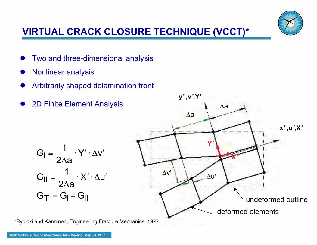
Two and three-dimensional analysis
Nonlinear analysis
Arbitrarily shaped delamination front
2D Finite Element Analysis
!
GI =1
2"a# $ Y # " $ v
GII =1
2"a# $ X # " $ u
GT = GI + GII
Y’
X’
y’ ,v’,Y’
x’ ,u’,X’
undeformed outline
deformed elements
!
"a
!
"a
!
"v'
!
"u'
*Rybicki and Kanninen, Engineering Fracture Mechanics, 1977
VIRTUAL CRACK CLOSURE TECHNIQUE (VCCT)*

MSC Software Composites Consortium Meeting, May 3-4, 2007
X'Li
i
*
Lx',u',X'
z',w',Z'local system
b
Z'Li
Y'Mi
GI =1
2!ab"Z'Li " w'Ll
#w'Ll
*( )
GII =1
2!ab"X'Li " u'Ll
#u'Ll
*( )
GIII =1
2!ab"Y'Li " v'Ll
#v'Ll
*( )
3D Finite Element Analysis
VIRTUAL CRACK CLOSURE TECHNIQUE -CONTINUED

MSC Software Composites Consortium Meeting, May 3-4, 2007
Testing of Stiffened Shear PanelBoeing, Philadelphia*
*Pierre Minguet, Boeing
Original Boeing ABAQUS ShellModel*
local detail of stringer foot
STRINGER STIFFENED PANEL SUBJECTEDTO SHEAR LOADING

MSC Software Composites Consortium Meeting, May 3-4, 2007
shell regionreplaced by local
3D model
intactdelaminated
y,v
x,u
z,w
u = v
u = v = 0
w = 0 w = 0
• Eight delamination lengths modeled• Short insert: a=82, 89, 95, 102 mm• Long insert: a=127, 203, 279, 356 mm
SHELL FE-MODEL WITH LOCAL 3DMODEL
MSC Software Composites Consortium Meeting, May 3-4, 2007
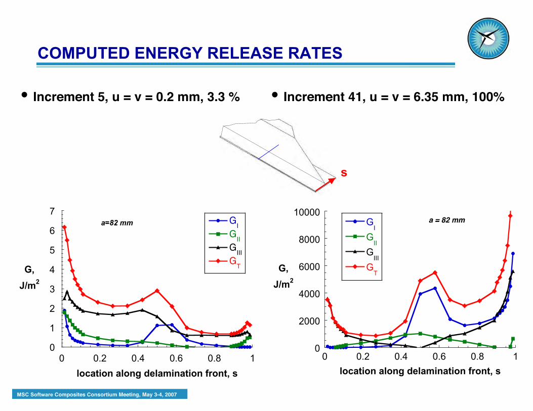
• Increment 5, u = v = 0.2 mm, 3.3 % • Increment 41, u = v = 6.35 mm, 100%
s
0
1
2
3
4
5
6
7
0 0.2 0.4 0.6 0.8 1
GI
GII
GIII
GTG,
J/m2
location along delamination front, s
a=82 mm
0
2000
4000
6000
8000
10000
0 0.2 0.4 0.6 0.8 1
GI
GII
GIII
GT
G,
J/m2
location along delamination front, s
a = 82 mm
COMPUTED ENERGY RELEASE RATES

MSC Software Composites Consortium Meeting, May 3-4, 2007
DECOHESION ELEMENTS FORSIMULATING DELAMINATION
CARLOS DAVILA
DURABILITY, DAMAGE TOLERANCE ANDRELIABILITY BRANCH
NASA LANGLEY RESEARCH CENTERHAMPTON, VA
MSC Software Composites Consortium Meeting, May 3-4, 2007
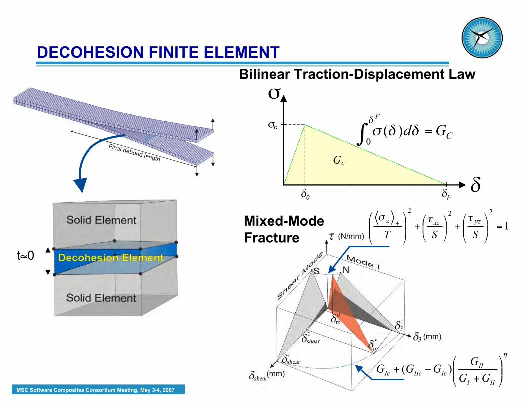
Mixed-ModeFracture
Final debond length
1
222
=!!"
#$$%
&+!
"
#$%
&+
!!
"
#
$$
%
&+
SST
yzxzz ''(
!
""#
$%%&
'
+(+
III
II
IcIIcIc
GG
GGGG )(
Bilinear Traction-Displacement Law
CGd
F
=! ""#"
0 )(
G
!
F
c
!
0
c
t≈0
DECOHESION FINITE ELEMENT
MSC Software Composites Consortium Meeting, May 3-4, 2007
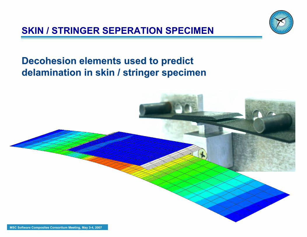
Decohesion Decohesion elements used to predictelements used to predictdelamination in skin / stringer specimendelamination in skin / stringer specimen
SKIN / STRINGER SEPERATION SPECIMEN
MSC Software Composites Consortium Meeting, May 3-4, 2007
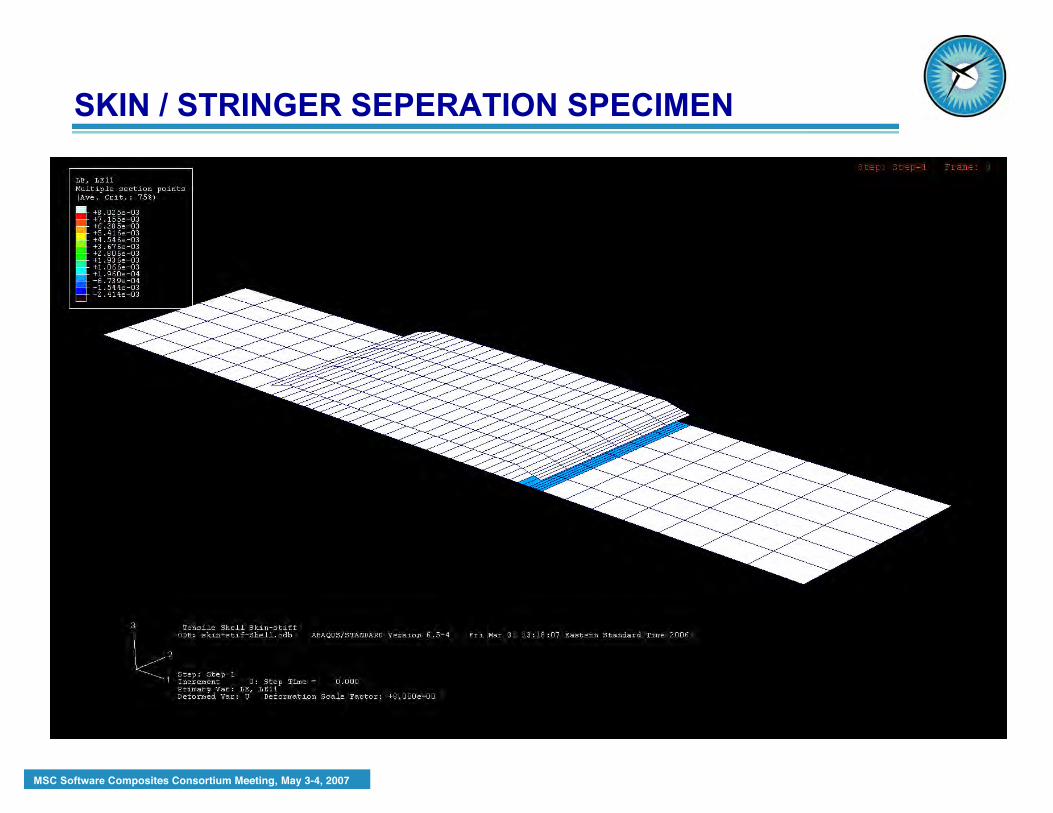
SKIN / STRINGER SEPERATION SPECIMEN

NTSB Board MeetingAA Flight 587
Structures InvestigationBrian K. Murphy - NTSB
Detailed Lug Analysis Team -NASA LaRC

MSC Software Composites Consortium Meeting, May 3-4, 2007
FORWARD
UP
Rear Lug
ClevisFitting
TitaniumBolt
MAIN ATTACHMENT FITTINGS
MSC Software Composites Consortium Meeting, May 3-4, 2007
LUG STRENGTH DETERMINATION
The strength of the lug was determined by:
• Finite element analysis
• Progressive failure analysis
• Post accident lug tests
MSC Software Composites Consortium Meeting, May 3-4, 2007
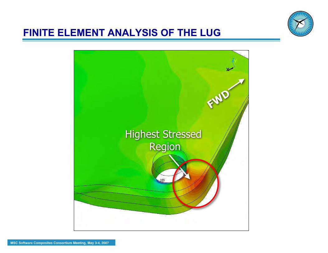
FINITE ELEMENT ANALYSIS OF THE LUG
FWD
Highest Stressed Region

MSC Software Composites Consortium Meeting, May 3-4, 2007
PROGRESSIVE FAILURE ANALYSIS
Extensive Damage

MSC Software Composites Consortium Meeting, May 3-4, 2007
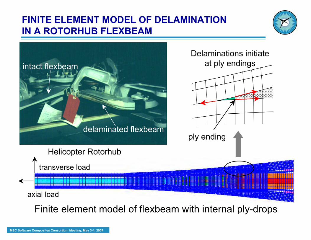
FINITE ELEMENT MODEL OF DELAMINATIONIN A ROTORHUB FLEXBEAM
GRETCHEN MURRIU.S. ARMY RESEARCH LABORATORY, VEHICLE
TECHNOLOGY DIRECTORATE
Resident at Durability, Damage Tolerance and ReliabilityBranch, NASA Langley Research Center
MSC Software Composites Consortium Meeting, May 3-4, 2007
Finite element model of flexbeam with internal ply-drops
Helicopter Rotorhub
intact flexbeam
delaminated flexbeamply ending
Delaminations initiateat ply endings
transverse load
axial load
FINITE ELEMENT MODEL OF DELAMINATIONIN A ROTORHUB FLEXBEAM

MSC Software Composites Consortium Meeting, May 3-4, 2007
delamination length
Gpeak GFE
VCCT used to calculate G asdelamination grows
N, cycles to delamination onset
GcGmax=cNb
Gmax
Fatigue toughness data for modeled material
Calculated fatiguelife curve
N, cycles to delamination onset
flex-beam strain
flexbeam test data
FLEXBEAM FATIGUE LIFE METHODOLOGY
MSC Software Composites Consortium Meeting, May 3-4, 2007
MIXED-MODE FAILURE CRITERIA FORDELAMINATION IN COMPOSITE LAMINATES
JAMES REEDER
NASA LANGLEY RESEARCH CENTERHAMPTON, VA
MSC Software Composites Consortium Meeting, May 3-4, 2007
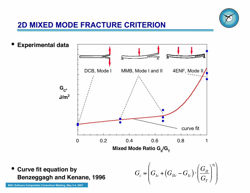
0 0.2 0.4 0.6 0.8 1
Mixed Mode Ratio GII/G
T
GC,
J/m2
DCB, Mode I 4ENF, Mode IIMMB, Mode I and II
curve fit
!
Gc
= GIc
+ GIIc"G
Ic( ) #G
II
GT
$
% &
'
( )
*$
%
& &
'
(
) )
• Curve fit equation byBenzeggagh and Kenane, 1996
• Experimental data
2D MIXED MODE FRACTURE CRITERION

MSC Software Composites Consortium Meeting, May 3-4, 2007
Mode III - ECT Specimen Proposed 3D failure criterion**
tearingmode III
**James Reeder, NASA Langley Research Center
Surface representation 2D plotrepresentation toobtain values
!
GT
GIc
+ GIIc"G
Ic( )G
II+G
III
GT
#
$ %
&
' (
)
+ GIIIc"G
IIc( )G
III
GII
+GIII
GII
+GIII
GT
#
$ %
&
' (
)* 1
PROPOSED 3D MIXED MODE FRACTURE CRITERION
MSC Software Composites Consortium Meeting, May 3-4, 2007
ANALYSIS TO PREDICT DELAMINATIONIN Z-PIN REINFORCED LAMINATES
JAMES RATCLIFFENATIONAL INSTITUTE OF AEROSPACE
HAMPTON, VA
Resident at Durability, Damage Tolerance andReliability Branch, NASA Langley Research Center
MSC Software Composites Consortium Meeting, May 3-4, 2007
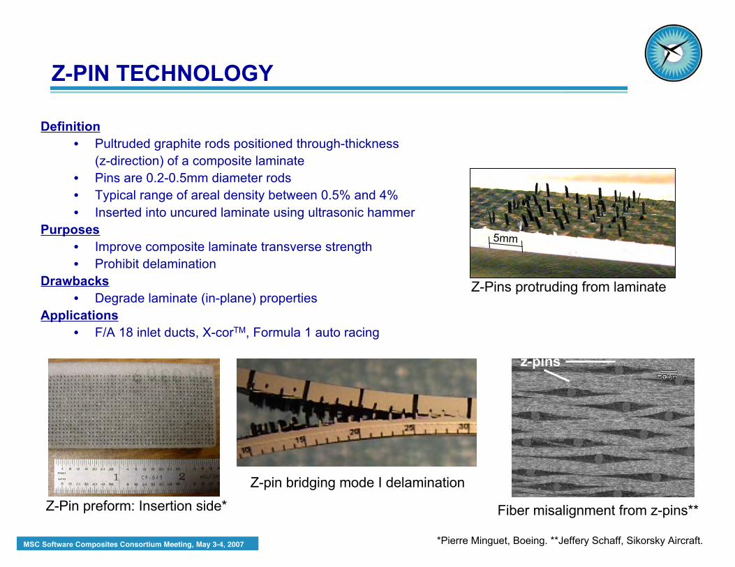
Definition• Pultruded graphite rods positioned through-thickness
(z-direction) of a composite laminate• Pins are 0.2-0.5mm diameter rods• Typical range of areal density between 0.5% and 4%• Inserted into uncured laminate using ultrasonic hammer
Purposes• Improve composite laminate transverse strength• Prohibit delamination
Drawbacks• Degrade laminate (in-plane) properties
Applications• F/A 18 inlet ducts, X-corTM, Formula 1 auto racing
Z-Pin preform: Insertion side*
*Pierre Minguet, Boeing. **Jeffery Schaff, Sikorsky Aircraft.
Fiber misalignment from z-pins**
z-pins
Z-Pins protruding from laminate
5mm
Z-PIN TECHNOLOGY
Z-pin bridging mode I delamination
MSC Software Composites Consortium Meeting, May 3-4, 2007
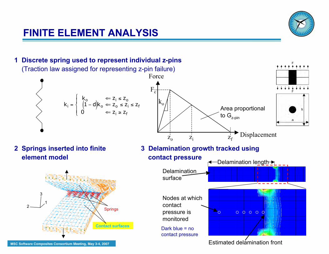
1 Discrete spring used to represent individual z-pins (Traction law assigned for representing z-pin failure)
2 Springs inserted into finite 3 Delamination growth tracked using element model contact pressure
Force
Displacement
Fc
zo zf
ko
zi
!
ki = ko " zi # zo
1 $ d( )ko " zo # zi # zf
0 " zi % zf
&
' (
) (
Contact surfaces
Springs1
2
3
Dark blue = nocontact pressure
Delaminationsurface
Estimated delamination front
Delamination length
Nodes at whichcontactpressure ismonitored
Area proportionalto Gz-pin
FINITE ELEMENT ANALYSIS
MSC Software Composites Consortium Meeting, May 3-4, 2007
z
yx
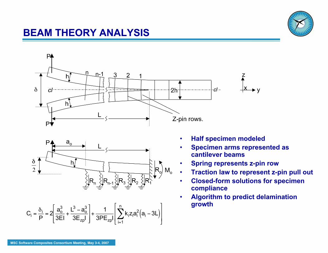
• Half specimen modeled• Specimen arms represented as
cantilever beams• Spring represents z-pin row• Traction law to represent z-pin pull out• Closed-form solutions for specimen
compliance• Algorithm to predict delamination
growth
!
Ci =" i
P= 2
ao3
3EI+
L3 #ao3
3EzpI
$
% & &
'
( ) )
+1
3PEzpIkiziai
2 ai #3L( )i=1
n
*$
%
& &
'
(
) )
BEAM THEORY ANALYSIS
n-1n
Rn-1Rn
L
Lao
MSC Software Composites Consortium Meeting, May 3-4, 2007
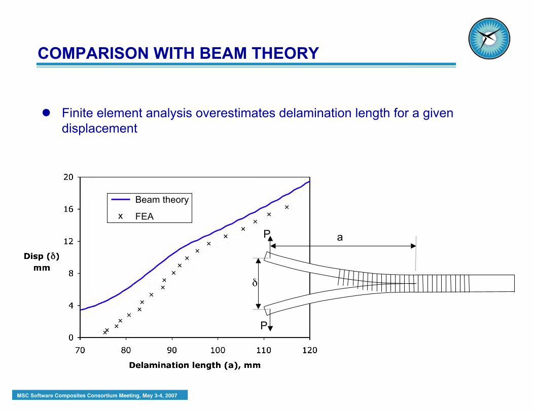
COMPARISON WITH BEAM THEORY
a
δ
P
P
Finite element analysis overestimates delamination length for a givendisplacement
Beam theory
FEAx

MSC Software Composites Consortium Meeting, May 3-4, 2007
COMPARISON WITH BEAM THEORY
a
δ
P
P
Finite element analysis results in better agreement with beam theorywhen decohesion elements used for delamination
Beam theory
FEAx

MSC Software Composites Consortium Meeting, May 3-4, 2007
• Many analysis studies involve a low Technology Readiness Level (TRL).Therefore, specialized tools are required which are not alwayscommercially available
• In many cases the finite element analysis software has to provide inputto specialized user subroutines. An adequate interface is required toenable appropriate communication with the user subroutines.
• The specialized analysis tools are often computationally expensive
CONCLUDING REMARKS